window MITSUBISHI DIAMANTE 1900 User Guide
[x] Cancel search | Manufacturer: MITSUBISHI, Model Year: 1900, Model line: DIAMANTE, Model: MITSUBISHI DIAMANTE 1900Pages: 408, PDF Size: 71.03 MB
Page 273 of 408

1993-96 MIRAGE CHASSIS SCHEMATIC
1993-96 MIRAGE CHASSIS SCHEMATIC
w/ HOT IN RUN OR START INTERMITTENT
WIPER
COLUMN
I-
I SWlTCH I
I INTERMITTENT
WIPER RELAY
II I I
I
VdRlABLE
INTERMITTENT
WIPER
CONTRDL
SWITCH WINDSHIELD
1 WINDSHIELD
WIPER MOTOR
WINDSHIELD
WASHER
nOTOR
r
I
1
-- LEFT
FRONT
POWER
WINDOW
NOTOR
w/o HOT IN RUN OR START INTERMITTENT
WIPER
COLUWN
SWITCH
DIAGRAM 72 93156852
93156853 DIAGRAM71
Page 278 of 408
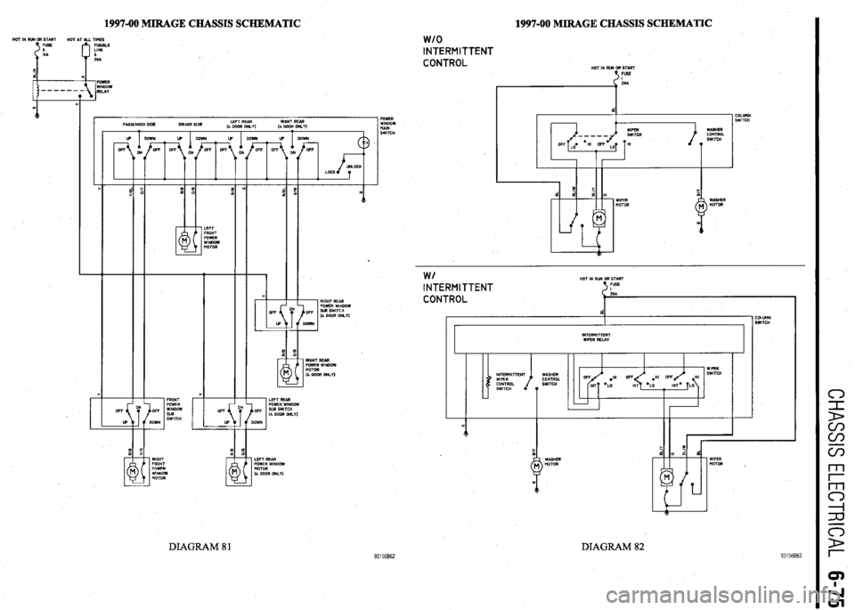
1997-00 MIRAGE CHASSIS SCHEMATIC HOT IN RR4 OR STMT
HOT AT ALL TIMES
FUSIBLE
LINK
6
SOA 1997-00 MIRAGE CHASSIS SCHEMATIC
1 POWER
WINDOW
tiAlN
SWITCH
w/o INTERMITTENT
CONTROL
HOT IN RUN OR START
t FUSE
COLUllN
SWITCH
LEFT REAR RIGHT REAR
4 DOOR or&Y)
(4WWOM.I)
I .
F ?E
d d a 0
WIPER WASHER
MOTOR MOTOR
.
93156862
W/ HOT IN RUN GR START INTERMITTENT FUSE 5
CONTROL
d COLUtlN
SWITCH
I r INTERMITTENT
WIPER RELAY
I I
WIPER
WASHER SWITCH
CONTROL .HI OFF HI
SWITCH
*LO MT= LO
T
1
LEFT REAR
POWER WINDOW
MOTOR
(4 GOOR ONLY) RIGHT
FRONT
POWER
WINDOW
MOTOR WIPER
MOTOR .
DIAGRAM 82 DIAGRAM 81
Page 369 of 408
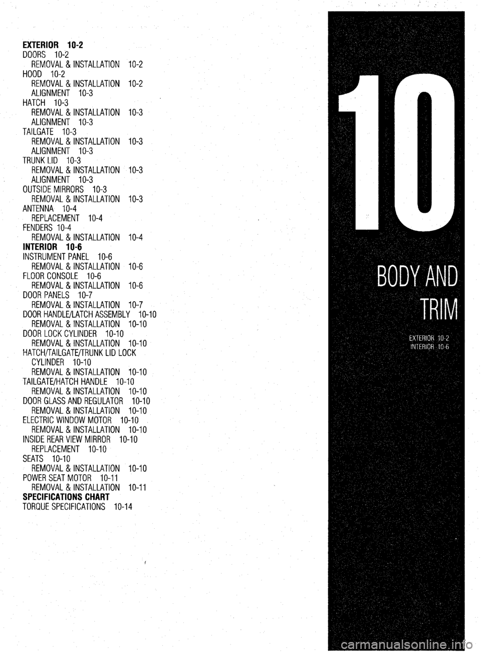
EXTERIOR IO-2
DOORS IO-2
REMOVAL&INSTALLATION IO-2
HOOD IO-2
REMOVAL&INSTALLATION IO-2
ALIGNMENT IO-3
HATCH IO-3
REMOVAL & INSTALLATION IO-3
ALIGNMENT IO-3
TAILGATE IO-3
REMOVAL & INSTALLATION IO-3
ALIGNMENT IO-3
TRUNK LID IO-3
REMOVAL &INSTALLATION IO-3
ALIGNMENT IO-3
OUTSIDE MIRRORS IO-3
REMOVAL &INSTALLATION IO-3
ANTENNA IO-4
REPLACEMENT IO-4
FENDERS IO-4
REMOVAL & INSTALLATION IO-4
INTERIOR 1
O-6 INSTRUMENTPANEL IO-6
REMOVAL & INSTALLATION IO-6
FLOOR CONSOLE IO-6
REMOVAL & INSTALLATION IO-6
DOOR PANELS IO-7
REMOVAL & INSTALLATION IO-7
DOORHANDLE/LATCHASSEMBLY IO-IO
REMOVAL &INSTALLATION IO-IO
DOOR LOCKCYLINDER IO-IO
REMOVAL &INSTALLATION IO-IO
HATCH/TAILGATE/TRUNKLID LOCK
CYLINDER IO-IO
REMOVAL &INSTALLATION IO-IO
TAILGATE/HATCH HANDLE IO-IO
REMOVAL &INSTALLATION IO-IO
DOORGLASSANDREGULATOR IO-IO
REMOVAL&INSTALLATION IO-IO
ELECTRIC WINDOW MOTOR IO-IO
REMOVAL &INSTALLATION IO-IO
INSIDE REAR VIEW MIRROR IO-IO
REPLACEMENT IO-IO
SEATS IO-IO
REMOVAL & INSTALLATION IO-IO
POWERSEATMOTOR IO-11
REMOVAL &INSTALLATION IO-11
SPECIFICATIONS CHART
TORQUE SPECIFICATIONS IO-14
4
Page 378 of 408

.
IO-10 BODYANDTRIM
4992 models>
10. Remove the retaining screws and the floor
console from the vehicle.
To
install: 11. Install the floor console in position in the ve-
hicle and secure with the retaining screws.
12. The remainder of installation is the reverse of
removal.
1. Ashtray or floor co
2. Switch or plug
REMOVAL&INSTALLATION
u See Figures 40 thru 49
1. Disconnect the negative battery cable.
2. If equipped with manual windows, insert a
ind the window regulator handle and
9315@38 Fig. 38 Floor console assemblv-1992-96 shop towel beh
Fig. 40 Remove the inside door rele
9315Gq39 Fia. 39 Floor console assemblv-1997-00 die cup retaining screw . . .
Diumante , I ,
r+Dn some models, the seat belts are routed
through the console. Carefully slide the belts
out of the hole.
7. The installation is the reverse of removal.
Front
1. Disconnect the negative battery cable. If
equipped with SRS, wrap the cable in insulated tape,
then wait at least 60 seconds before continuing to al-
low the SRS system time to disable.
9315opO3 Fig. 42 Remove the inside pull handle re-
If equipped with SRS, be careful not to let
the console bump against the SRS-ECU dur-
ing removal and installation. taining screw cover , . .
2. If equipped, remove the rear floor console.
3. If necessary, remove the ashtray and cup
holder assemblies.
4. If equipped, remove the carpet inserts from
the floor console assembly.
5. On manual transaxle equipped models, re-
move the manual transaxle shifter knob.
6. On automatic transaxle equipped models, re-
move the transaxle shift lever trim plate.
7. Remove the screw plugs in the side covers.
Remove the retainer screws and the side covers from
the vehicle.
8. Remove the front mounting screw cover from
the floor console.
9. Label and detach the electrical wire harness
connections for the floor console. Fig. 44 Release the front retaining clips,
and lift the handle and switch assembly
from the door oanel push the retainer clip outward. Once the clip is re-
moved, remove the window glass requlator handle
and escutcheon.
3. If equipped with power windows/locks, re-
move the escutcheon panel (control panel) and de-
tach the electrical connectors.
4. If equipped, remove the door grip/pull handle
mounting screws and the grip from the door panel.
5. Remove the door pull handle cover. Remove
the pull handle, if equipped.
6. Remove the door trim panel retaining screws.
7. Pull the door panel gently from the door. The
panel is retained by spring clips. To separate the
clips from the door, slide a small prytool behind the
clip and carefully pull the clip, with the door panel,
outward. Try not to bend the door panel or damaqe
may occur..
Fig. 41 . . . then remove the inside door re-
lease handle cup
Fig. 43
V . . then remove the inside pull han-
dle retaining screw
Fig. 45 Detach the electrical connectors
from the door lock and window switches
isembly ,,,’ ” then remove the switch plate/handle as-
Page 380 of 408
.
1042 BODYANDTRIM
P
I. i%lllUVt: LIE UUUI yldbb Uy lllllll!J It up ana out ot me ease, wnicn IS glueo onto tne wmasnlela. 1 ne
of the door.
installation is the reverse of the removal procedure. If
8. Remove the installation bolts holding the
the mirror base falls off of the windshield it can be in-
regulator to the door.
stalled as follows:
I
9. If equipped with electric windows discnnnad
1. Scrape the base mounting area with a razor
LllC vvllllly L” t,te Wlll”“W lll”l”l.
blade to remove the old adhesive.
I 10. Remove the regulator through the access hole
2. Thoroughly clean the base mounting ara.
’ in the door.
3. Obtain a mirror adhesive kit. Apply the clean-
To install:
ing compound to the windshield in the area that the
11. When reinstalling the regulator, apply a light
base is to be mounted. Allow to dry.
coat of multipurpose grease to the moving parts.
4. Apply the adhesive to both the base plate and
12. Install the regulator and tighten the bolts fin-
the windshield. Install the base to the glass. Hold in
ger-tight.
position until the adhesive has a chance to set. Make
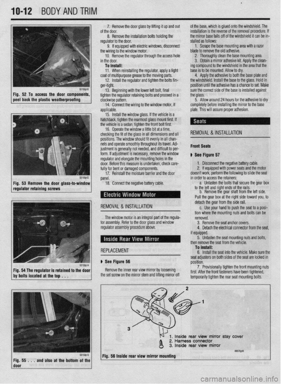
5315oQ18 Fig. 52 To access the door components,
peel back the plastic weatherproofing 13. Beginning with the lower left bolt, final
tighten the regulator retaining bolts and p
clockwise pattern.
14.
applic
+r roceed in a
Connect the wiring to the window motor, if
able.
Install the window glass. If the vehicle is a
lack, tighten the rearmost glass mount first. If
hicle is a sedan, tighten the front bolt first.
.
13. hatcht
the ve’
16. Uperate the window a little bit at a time,
checking the fit of the glass in all dimensions and all
positions. The window should fit evenly in all chan-
nels and operate smoothly throughout its travel. Ad-
ius~ment is rener;IIIv not needed. and diffirlllf +n nor- . ._ ~ _.._. - ., _.
___.-, - - _ lll”“ll I” pm
i&h. If adiustment is necessarv, remove thp win&N I..” . . . ..“1.. regulator and elongate the mointing holes in the
door. Before this measure is undertaken, check care-
fully for bent or damaged components.
17. Reinstall the moisture barrier and the door sure the correct side of the base is installed against
the glass.
5. Allow around 24 hours for the adhesive to dry
completely before installing the mirror to the base
plate. This will assure proper adhesion.
REMOVAL & INSTALLATION
Front Seats
* err ei
I ovv rlgure 57 .
1, Disconnect the negative battery cable.
2. If equipped with power seats and the motor
doesn’t work, perform the following to slide the seat
panel.
18. Conned the negative battery Cable. in order to acdess the retainers:
-
a. Unfasten the bolts that secure the gear box
to the left and right ends of the rails.
b. Remove the gear shaft from the left side.
Pull the gear box at the right side toward you, to
I REMOVAL & INSTALLATION detach the gear from the side rail.
c. Use your hand to push the seat to a posi-
tion where the mounting nuts and bolts can be
The window motor is an integral part nf the renlrla-
romnvPrl
-’ .“- ‘-J-.- tor assembly. Refer to the door Glass and window
regulator assembly procedure above. IYII,“.““. 3. Remove the seat anchor covers.
4. Detach the electrical connector from the seat,
if m~innd I I, “y”y~Y”. 5. Unfasten the seat mountina nuts and bolts.
1 REPLACEMENT To install:
c
b Ser f Floure 56
Yap- ~~
Remove the inner rear view mirror by loosening
the set screw on the mirror stem and lifting mirror off seat adjusters on both sides of the seat are locked in
rmritinn p”3111”ll.
7. Provisionally tighten the front mounting nuts
first. After the front fasteners have been tightened,
tomnnr.,rilw tinhton thn co.-ar co.,+ m qunting bolts. then remove the seat from the vehicle.
1, Inside rear view mirror stay ‘cover
2. Harness connector
3. Inside rear view mirror
’ ~;f!i!i...andalsoatthebottom~~~~ Fig. 56 Inside rear view mirror mbuntlng
I
Page 404 of 408
11-22 MASTER INDEX
REMOVAL&INSTALLATION 9-3
BRAKE MASTERCYLINDER I-41
FLUIDRECOMMENDATIONS 1-41
LEVELCHECK I-41
BRAKE OPERATING SYSTEM B-2
BRAKEPADS 9-8
INSPECTION 9-11
REMOVAL & INSTALLATION 9-8
'
BRAKESHOES 9-16
ADJUSTMENTS 9-18
INSPECTION 9-16
REMOVAL&INSTALLATION 9-17
BRAKESHOES 9-23
ADJUSTMENT 9-24
REMOVAL & INSTALLATION 9-23
BUY OR REBUILD? 3-57
CABLE(S) 9-20
ADJUSTMENT 9-22
REMOVAL & INSTALLATION 9-20
CAMSHAFT POSITIONSENSOR 4-14
OPERATION 4-14
REMOVAL &INSTALLATION 4-14
TESTING 4-14
CAMSHAFT, BEARINGSAND LIFTERS 3-48
INSPECTION 3-53
REMOVAL & INSTALLATION 3-48
CENTERBEARING 7-15
REMOVAL & INSTALLATION 7-15
CHARGING SYSTEM 2-8
CHASSISGREASING l-43
CAR WASHING 1-43
INTERIOR CLEANING l-44
WAXING l-43
CIRCUIT BREAKERS 6-28
CIRCUIT PROTECTION 6-27
CLEARING CODES 4-27
CLEARING CODES 4-28
WITHASCANTOOL 4-28
WITHOUTASCANTOOL 4-28
CLUTCH CABLE 7-9
ADJUSTMENT 7-9
REMOVAL AND INSTALLATION 7-9
CLUTCH MASTER CYLINDER 7-9
REMOVALANDINSTALLATION 7-9
CLUTCHSLAVECYLINDER 7-9
HYDRAULIC SYSTEM BLEEDING 7-9
REMOVAL &INSTALLATION 7-9
CLUTCH 7-7
CLUTCHMASTERCYLINDER l-42
FLUIDRECOMMENDATIONS l-42
LEVELCHECK l-42
COMBINATION SWITCH 8-29
REMOVAL &INSTALLATION 8-29
COMPONENTLOCATIONS 4-16
CONTROL CABLES 6-12
ADJUSTMENT 6-12
CONTROL PANEL 6-12
REMOVAL&INSTALLATION 6-12
COOLINGSYSTEM l-39
DRAIN &REFILL I-40
FLUIDRECOMMENDATIONS l-39
FLUSHINGANDCLEANING THESYST
EM-41
LEVELCHECK l-39
TESTING FOR LEAKS l-39
CRANKCASEVENTILATIONSYSTEM 4-2
COMPONENTTESTING 4-2
OPERATION 4-2
REMOVAL &INSTALLATION 4-2
CRANKSHAFTDAMPER 3-36 REMOVAL &INSTALLATION 3-36
CRANKSHAFTANDCAMSHAFTPOSITIONSENSORS 2-7
CRANKSHAFTANDCAMSHAFTPOSITIONSENSORS 2-5
CRANKSHAFTPOSlTlONSENSOR/CRANKANGLESENSOR 4-14
OPERATION 4-14
REMOVAL&INSTALLATION 4-15
TESTING 4-15
CRUISE CONTROL 6-13
CV-BOOTS I-21
INSPECTION I-21
CYLINDER HEAD 3-23
REMOVAL & INSTALLATION 3-23
CYLINDER HEAD 3-60
DETERMINIG ENGINE CONDITION 3-57
COMPRESSION TEST 3-57
OIL PRESSURETEST 3-57
DIAGNOSIS AND TESTING 9-24
DIAGNOSISANDTESTING 2-2
DIAGNOSISANDTESTING 2-5
DIAGNOSTICTROUBLECODES 4-27
DIAGNOSTICTROUBLECODES 4-28
FLASH OUTCODELIST 4-32
DIMMER SWITCH 6-19
REMOVAL &INSTALLATION 6-19
DISC BRAKES 9-8
DISCONNECTING THE CABLES 6-7
DISTRIBUTOR IGNITION SYSTEM 2-2 f
DISTRIBUTOR 2-4
INSTALLATION 2-4
REMOVAL&INSTALLATION 2-4
DISTRIBUTORCAPANDROTOR l-25
INSPECTION l-25
REMOVAL&INSTALLATION l-25
DISTRIBUTORLESS IGNITION SYSTEM 2-5
DO'S l-4
DON'TS l-6
DOORGLASSANDREGULATOR lo-10
REMOVAL &INSTALLATION IO-IO
DOOR HANDLE/LATCHASSEMBLY IO-IO
REMOVAL & INSTALLATION IO-IO
DOORLOCKCYLINDER IO-IO
REMOVAL & INSTALLATION IO-IO
DOOR PANELS IO-7
REMOVAL & INSTALLATION IO-7
DOORS IO-2
REMOVAL &INSTALLATION IO-2
DRlVEAXLE(AWD GALANTONLY) l-10
DRIVELINE 7-14
DRIVEN DISC AND PRESSURE PLATE 7-7
DRIVESHAFTAND U-JOINTS 7-14
DRIVESHAFT BALANCING 7-15
REMOVAL & INSTALLATION 7-14
U-JOINTREPLACEMENT 7-14
DRUM BRAKES 9-15
ELECTRIC WINDOW MOTOR IO-IO
REMOVAL &INSTALLATION IO-IO
ELECTRICALCOMPONENTS 6-2
CONNECTORS 6-4
GROUND 6-3
LOAD 6-3
POWERSOURCE 6-2
PROTECTIVE DEVICES 6-3
SWITCHES&RELAYS 6-3
WIRING & HARNESSES 6-3
ELECTRONIC ENGINE CONTROLS 4-7
EMISSION CONTROLS 4-2
ENGINE BLOCK 3-65
ASSEMBLY 3-67
DISASSEMBLY 3-65
Page 407 of 408
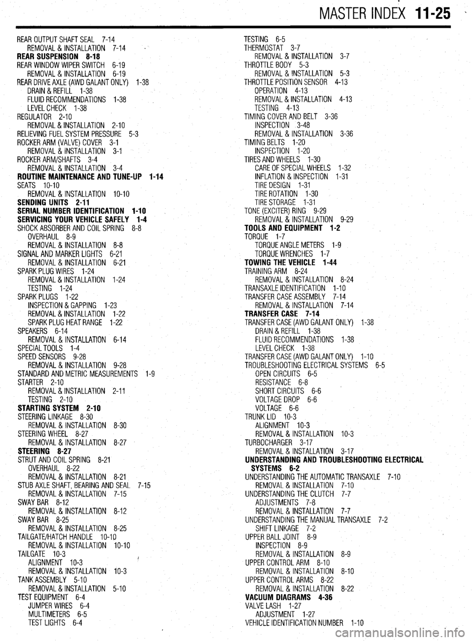
MASTER INDEX 11-25 -
REAROUTPUTSHAFTSEAL 7-14
TESTING 6-5
REMOVAL & INSTALLATION 7-14
' THERMOSTAT 3-7
REAR SUSPENSION 8-18 REMOVAL & INSTALLATION 3-7
REAR WINDOW WIPER SWITCH 6-19 THROTTLE BODY 5-3
REMOVAL&INSTALLATION 6-19 REMOVAL & INSTALLATION 5-3
REARDRlVEAXLE(AWDGALANTONLY) l-38
THROTTLEPOSITIONSENSOR 4-13
DRAIN &REFILL 1-38
OPERATION 4-13
FLUIDRECOMMENDATIONS 1-38 , REMOVAL&INSTALLATION 4-13
LEVELCHECK l-38
TESTING 4-13
REGULATOR 2-10 TIMING COVERAND BELT 3-36
REMOVAL&INSTALLATION 2-10
INSPECTION 3-48
RELIEVING FUELSYSTEM PRESSURE 5-3 REMOVAL & INSTALLATION 3-36
ROCKERARM(VALVE)COVER 3-1
TIMING BELTS l-20
REMOVAL & INSTALLATION 3-1
INSPECTION I-20
ROCKER ARM/SHAFTS 3-4
TIRESANDWHEELS I-30
REMOVAL & INSTALLATION 3-4
CAREOFSPECIALWHEELS l-32
ROUTINE MAINTENANCE AND TUNE-UP 1-14 INFLATION & INSPECTION I-31
SEATS IO-IO
TIRE DESIGN I-31
REMOVAL&INSTALLATION IO-IO TIRE ROTATION I-30
SENDING UNITS 2-11
TIRESTORAGE I-31
SERIAL NUMBER IDENTIFICATION l-10
TONE (EXCITER) RING 9-29
SERVICING YOUR VEHICLE SAFELY I-4
REMOVAL & INSTALLATION 9-29
SHOCKABSORBERAND COILSPRING 8-8
TOOLS AND EQUIPMENT 1-2
OVERHAUL 8-9
TORQUE 1-7
REMOVAL&INSTALLATION 8-8 TORQUEANGLEMETERS l-9
SIGNAL AND MARKER LIGHTS 6-21
TORQUEWRENCHES l-7
REMOVAL & INSTALLATION 6-21
TOWING THE VEHICLE 1-44
SPARKPLUG WIRES 1-24
TRAINING ARM 8-24
REMOVAL&INSTALLATION 1-24
REMOVAL & INSTALLATION 8-24
TESTING 1-24
TRANSAXLEIDENTIFICATION I-10
SPARKPLUGS l-22
TRANSFER CASE ASSEMBLY 7-14
INSPECTION &GAPPING l-23
REMOVAL & INSTALLATION 7-14
REMOVAL&INSTALLATION 1-22
TRANSFER CASE 7-14
SPARKPLUGHEATRANGE 1-22
TRANSFERCASE(AWD GALANT ONLY) 1-38
SPEAKERS 6-14
DRAIN &REFILL 1-38
REMOVAL & INSTALLATION 6-14
FLUIDRECOMMENDATIONS 1-38
SPECIALTOOLS 1-4
LEVELCHECK 1-38
SPEED SENSORS 9-28
TRANSFERCASE(AWDGALANTONLY) I-10
REMOVAL & INSTALLATION 9-28
TROUBLESHOOTING ELECTRICALSYSTEMS 6-5
STANDARDANDMETRIC MEASUREMENTS l-9
OPEN CIRCUITS 6-5
STARTER 2-10
RESISTANCE 6-8
REMOVAL&INSTALLATION 2-11
SHORT CIRCUITS 6-6
TESTING 2-10
VOLTAGEDROP 6-6
STARTING SYSTEM 2-10
VOLTAGE 6-6
STEERING LINKAGE 8-30
TRUNK LID IO-3
REMOVAL &INSTALLATION 8-30
ALIGNMENT IO-3
STEERING WHEEL 8-27
REMOVAL & INSTALLATION IO-3
REMOVAL &INSTALLATION 8-27
TURBOCHARGER 3-17
STEERING 8-27
REMOVAL & INSTALLATION 3-17
STRUT AND COIL SPRING
8-21
UNDERSTANDING AND TROUBLESHOOTING ELECTRICAL
OVERHAUL 8-22
SYSTEMS 6-2
REMOVAL & INSTALLATION 8-21
UNDERSTANDINGTHEAUTOMATICTRANSAXLE 7-10
STUBAXLESHAFT,BEARlNG AND SEAL 7-15
REMOVAL & INSTALLATION 7-10
REMOVAL&INSTALLATION 7-15
UNDERSTANDINGTHECLUTCH 7-7
SWAY BAR 8-12
ADJUSTMENTS 7-8
REMOVAL 8, INSTALLATION 8-12
REMOVAL&INSTALLATION 7-7
SWAY BAR 8-25
UNDERSTANDINGTHE MANUALTRANSAXLE 7-2
REMOVAL&INSTALLATION 8-25
SHIFT LINKAGE 7-2
TAILGATE/HATCH HANDLE lo-19
UPPER BALLJOINT 8-9
REMOVAL &INSTALLATION lo-10
INSPECTION 8-9
TAILGATE IO-3
REMOVAL &INSTALLATION 8-9
ALIGNMENT IO-3 i'
UPPER CONTROLARM 8-10
REMOVAL & INSTALLATION IO-3
REMOVAL & INSTALLATION 8-10
TANKASSEMBLY 5-10
UPPER CONTROL ARMS 8-22
REMOVAL&INSTALLATION 5-10
REMOVAL & INSTALLATION 8-22
TEST EQUIPMENT 6-4
VACUUM DIAGRAMS 4-36
JUMPER WIRES 6-4
VALVE LASH 1-27
MULTIMETERS 6-5
ADJUSTMENT 1-27
TEST LIGHTS 6-4
VEHICLE IDENTIFICATION NUMBER I-10