open gas tank MITSUBISHI DIAMANTE 1900 Repair Manual
[x] Cancel search | Manufacturer: MITSUBISHI, Model Year: 1900, Model line: DIAMANTE, Model: MITSUBISHI DIAMANTE 1900Pages: 408, PDF Size: 71.03 MB
Page 15 of 408
*
l-16 GENERALINFORMATIONAND MAINTENANCE
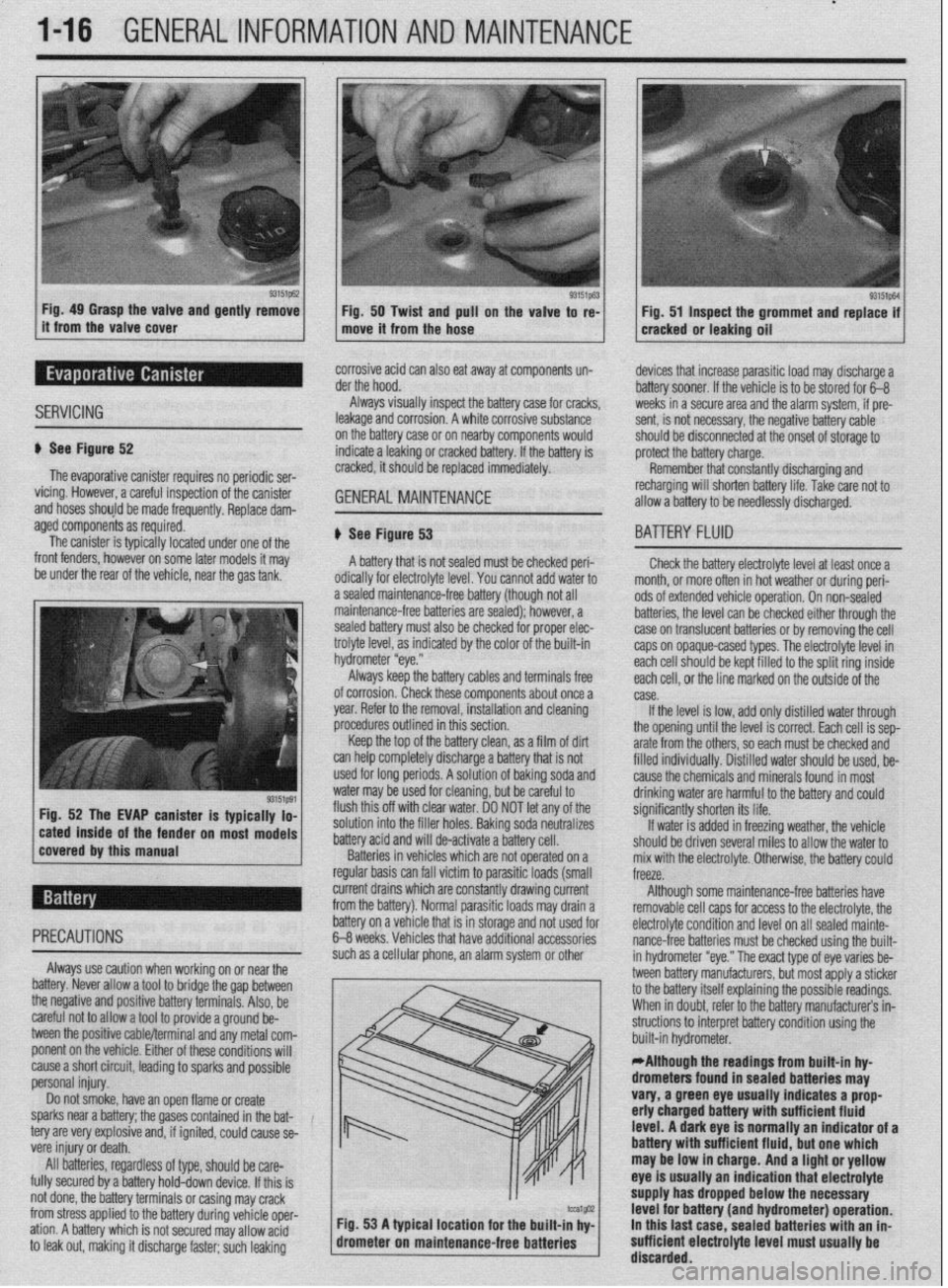
Fig. 49 Grasp the valve and gently remove
Fig. 50 Twist and pull on the valve to re-
it from the valve cover
move it from the hose Fig. 51 Inspect the grommet and replace if
cracked or leaking oil
SERVICING
corrosive acid can also eat away at components un-
der the hood.
Always visually inspect the battery case for cracks,
leakage and corrosion. A white corrosive substance
u See Figure 52
The evaporative canister requires no periodic ser-
vicing. However, a careful inspection of the canister
and hoses should be made frequently, Replace dam- on the battery case or on nearby components would
indicate a leaking or cracked battery. If the battery is
cracked, it should be replaced immediately. GENERALMAINTENANCE '_
devices that increase parasitic load may discharge a
battery sooner. If the vehicle is to be stored for 6-B
weeks in a secure area and the alarm system, if pre-
sent, is not necessary, the negative battery cable
should be disconnected at the onset of storage to
protect the battery charge.
Remember that constantly discharging and
recharging will shorten battery life. Take rare not to
allow a battery to be needlessly discharged.
aged components as required.
The canister is typically located under one of the
front fenders, however on some later models it may
be under the rear of the vehicle, near the gas tank,
r on most models # See Figure 53
A battery that is not sealed must be checked peri-
odically for electrolyte level. You cannot add water to
a sealed maintenance-free battery (though not all
maintenance-free batteries are sealed); however, a
sealed battery must also be checked for proper elec-
trolyte level, as indicated by the color of the built-in
hydrometer “eye.”
Always keep the battery cables and terminals free
of corrosion. Check these components about once a
year. Refer to the removal, installation and cleaning
procedures outlined in this section,
Keep the top of the battery clean, as a film of dirt
can help completely discharge a battery that is not
used for long periods. A solution of baking soda and
water may be used for cleaning, but be careful to
flush this off with clear water. DO NOT let any of the
solution into the filler holes. Baking soda neutralizes
battery acid and will de-activate a battery cell.
Batteries in vehicles which are not operated on a
regular basis can fall victim to parasitic loads (small
BA-ITERY FLUID
Check the battery electrolyte level at least once a
month. or more often in hot weather or during peri-
ods of extended vehicle operation. On non-sealed
batteries, the level can be checked either through the
case on translucent batteries or by removing the cell
caps on opaque-cased types. The electrolyte level in
each cell should be kept filled to the split ring inside
each ceil, or the line marked on the outside of the
case.
If the level is low, add only distilled water through
the opening until the level is correct. Each cell is sep-
arate from the others, so each must be checked and
filled individuallv. Distilled water should be used, be-
cause the chemicals and minerals found in most
drinking water are harmful to the battery and could
significantly shorten its life.
If water is added in freezing weather, the vehicle
should be driven several miles to allow the water to
mix with the electrolyte. Otherwise, the battery could
freeze.
current drains which are constantly drawing current
from the battery). Normal parasitic loads may drain a Although some maintenance-free batteries have
removable cell caos for access to the electrolyte, the
cause a short circuit, leading to sparks and possible
personal injury.
Do not smoke, have an open flame or create
sparks near a battery; the gases contained in the bat-
tery are very explosive and, if ignited, could cause se-
vere injury or death.
All batteries, regardless of type, should be care-
fully secured by a battery hold-down device. If this is
not done, the battery terminals or casing may crack
from stress applied to the battery during vehicle oper-
ation. A battery which is not secured may allow acid
to leak out, making it discharge faster; such leaking m / built-in hydrometer. .
*Although the readings from built-in hy-
drometers found in sealed batteries may
vary, a green eye usually indicates a prop
erly charged battery with sufficient fluid
level. A dark eye is normally an indicator of a
battery wlth sufficient fluid, but one which
may be low in charge. And a light or yellow
eye is usually an indication that electrolyte
supply has dropped below the necessary
tcu1@32 Fig. 53 A typical location for the built-in hv- level for battery (and hydrometer) operation.
drometer on maintenan
ce-free batteries ’ I In this last case. sealed batteries with an in-
sufficient electrolyte level must usually be
’ discarded.
Page 39 of 408
l-40 GENERALINFORMATIONAND MAINTENANCE
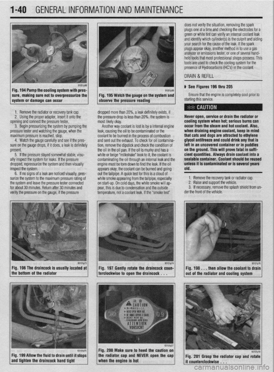
aiffiip98 Fig. 194 Pump the cooling system with pres-
sure, making sure not to overpressurize the
1 system or damage can occur
1. Remove the radiator or recovery tank cap.
2. Using the proper adapter, insert it onto the
opening and connect the pressure tester,
3. Begin pressurizing the system by pumping the
pressure tester and watching the gauge, when the
maximum pressure is reached, stop.
4. Watch the gauge carefully and see if the pres-
sure on the gauge drops, if it does, a leak is definitely
present.
5. If the pressure stayed somewhat stable, visu-
ally inspect the system for leaks, If the pressure
dropped, repressurize the system and then visually
inspect the system.
,
/ observe the pressure reading “@‘p~ 1 Fig 195 Watch the gauge on the system and
dropped more than 20%, a leak definitely exists, if
the oressure droo is less than 20%. the svstem is
most likely okay:
, cooling system when hot; serious burns can
Another way coolant is lost is by a internal engine occur from the steam and hot coolant. Also,
leak, causing the oil to be contaminated or the when draining engine coolant, keep in mind
coolant to be burned in the process of combustion that cats and dogs are attracted to ethylene
and sent out the exhaust. To check for oil contamina- glyeol antifreeze and could drink any that is
tion, remove the dipstick and check the condition of left in an uncovered container or in puddles
the oil in the oil pan. If the oil is murky and has a on the ground. This will prove fatal in suffi-
white or beige “milkshake” look to it, the coolant is cient quantities. Always drain coolant into a
contaminating the oil through an internal leak and the sealable container. Coolant should be reuser
enqine must be torn down to find the leak. If the oil mless it is contaminated or is several years
6. If no signs of a leak are noticed visually, pres-
surize the system to the maximum pressure rating of
the system and leave the uressure tester connected
fl sr about 30 minutes. Return after 30 minutes and
V erify the pressure on the gauge, if the pressure does not verify the situation, removing the spark
plugs one at a time and checking the electrodes for a
green or white tint can verify an internal coolant leak
and identify which cylinder(s) is the culprit and aiding
your search for the cause of the leak. If the spark
plugs appear okay, another method is to use a gas
analyzer or emissions tester, or one of several hand-
held tools that most professional shops possess. This
tools are used to check the cooling system for the
presence of Hydrocarbons (HC’s) in the coolant.
DRAIN & REFILL
p See figures 196 thru 205
Ensure that the engine is completely cool prior to
starting this service.
Never open, service or drain the radiator or
Ippears okay, the coolant can be burned and going
jut the tailpipe. A quick test for this is a cloud of
Nhite smoke appearing from the tailpipe, especially
In start-up. On cold days, the white smoke will ap-
Iear, this is due to condensation and the outside
emperature, not a coolant leak. If the “smoke test”
Fig. 196 The draincock is usually located at
Fig. 197 Gently rotate the draincock coun-
the bottom of the radiator
terclockwise to open the draincock . . .
Fig. 199 Allow the fluid to drain until it stops
and tighten the draineock hand tight
93151p27
1. Remove the recovery tank or radiator cap.
2, Raise and support the vehicle.
3. If necessary, remove the splash shield from un
ler the front of the vehicle.
93im76 Fig, 198 . _ . then allow the coolant to drain
out of the radiator and cooling system
Fig. 200 Make sure to heed the caution on
the radiator cap and NEVER open the cap
1 when the engine is hot ,, Fig. 201 Grasp the radiator cap and rotate
it counterclockwise . . .
Page 40 of 408
.
GENERALINFORMATIONAND MAINTENANCE l-41
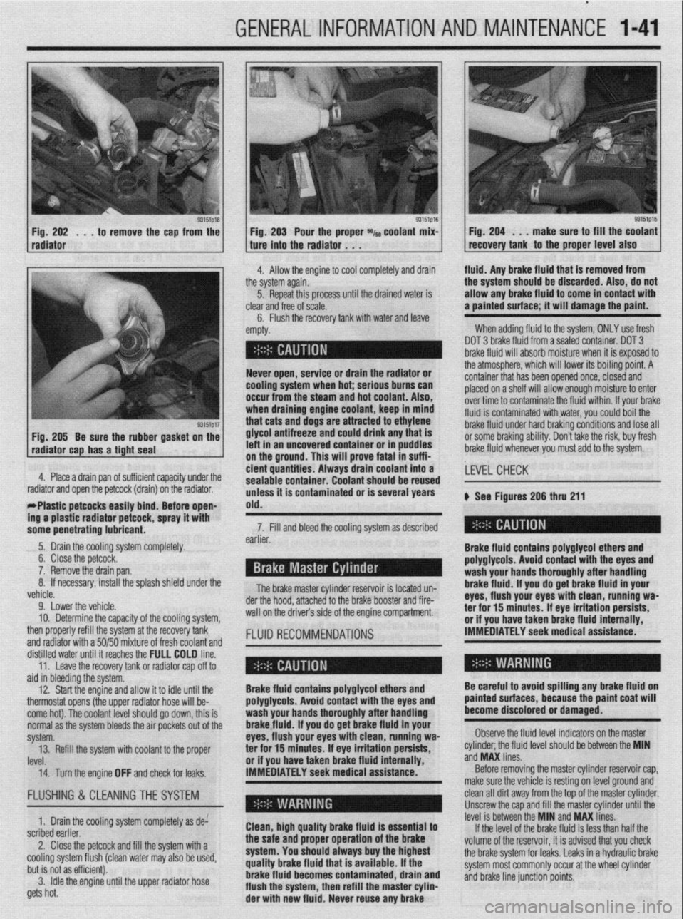
93151p18 Fig. 202 . , . to remove the cap from the
radiator
93151p17 Fig. 205 Be sure the rubber gasket on the
radiator cap has a tight seal e Fig. 203 Pour the proper *I~ coolant mix- 1 Fig. 204 . . . make sure to fill the coolant
recovery tank to the proper level also ture into the radiator . . .
.I
4. Allow the engine to cool completely and drain fluid. Any brake fluid that is removed from
ie system again.
5. Repeat this processuntil the drained water is
lear
and free of scale.
6. Flush the recovery tank with water and leave ’
mpty. the system should be discarded. Also, do not
allow any brake fluid to come in contact with
a painted surface; it will damage the paint.
When adding fluid to the system, ONLY use fresh
DOT 3 brake fluid from a sealed container. DOT 3
brake fluid will absorb moisture when it is exposed to
.a . . . , .*a. . . * .*. . .
- Never open, service or drain the radiator or
cooling system when hot; serious bums can
occur from the steam and hot coolant. Also,
when draining engine coolant, keep In mind
that cats and dogs are attracted to ethylene
glycol antifreeze and could drink any that is
left in an uncovered container or in puddles
on the ground. This will prove fatal in suffi-
4. Place a drain pan of suff i ’ 1 . . . ..I .I. 1,~ cient quantities. Always tne atmospnere, wnrcn wnr rower 1r.s oourng pomr. A
container that has been opened once, closed and
placed on a shelf will allow enough moisture to enter
over time to contaminate the fluid within. If your brake
fluid is contaminated with water, you could boil the
brake fluid under hard braking conditions and lose all
or some braking ability. Don’t take the risk, buy fresh
brake fluid whenever you must add to the system.
crenr capacrry unaer me
drain) on the radiator.
rrrasuc perwcss easuy bind; Before open-
ing a plastic radiator petcock, spray it with
some penetrating lubricant. drain coolant into a
earner. sealable container. Coolant should be reused
unless it is contaminated or is several years
old.
The brake master cylinder ~a~~~~r,~~ :A I~nnL.4 n-n 7. Fill and bleed the cooling system as described
Brake fluid contains polyglycol ethers and
polyglycols. Avoid contact with the eyes and ,LEVEL CHECK
wash your hands thoroughly after handling
brake fluid. If vou do oet brake fluid in vour
eyes, flush your eyeswith clean, runniug wa-
a-.. ‘Y-- ar -l-..n-- II -.._ I____ k See Figures 206 thru 211
.a-11-- - __-PA._ radiator and open the petcock (
- w&1--x3_ --mm.._..- . . ..-I...
5. Drain the cooling system completely.
6. Close the petcock.
7. Remove the drain pan.
If necessary, install the splash shield under the 8.
L.-l
venicie.
9. Lower the vehicle.
10. Determine the capacity of the cooling system,
then properly refill the system at the recovery tank
and radiator with a 50/50 mixture of fresh coolant and
fKm”“ll 15 IUMLC” “II- brake booster and fire- der the hood, attached to the
wall on the drivers side of the engine compartment.
FLUID RECOMMENDATIONS rer mr 13 mmures. IT eye irriIauon persim, or if you have taken brake fluid internally,
IMMEDIATELY seek medical assistance.
ala in oreerring me sysrem.
12. Start the engine and allow it to idle until the
thermostat opens (the upper radiator hose will be-
come hot). The coolant level should go down, this is
normal as the system bleeds the air pockets out of the
svstem.
IRVf!l ._._. 14. Turn the engine OFF and check for leaks. IMMEDIATELY seek medical assistance.” Brake fluid contains polyglycol ethers and
polyglycols. Avoid contact with the eyes and
wash your hands thoroughly after handling
brakefluid. If you do get brake fluid in your
eyes, flush your eyes with clean, running wa-
or if vou have taken brake fluid internallv.
Before removing the master cylinder reservoir cap,
make sure the vehicle is resting on level ground and Be careful to avoid spilling any brake fluid on
painted surfaces, because the paint coat will
become discolored or damaged.
Observe the fluid level indicators on the master
._ ._ __
‘eve1 should be between the MIN
ano
ivw unes. 13. Refill the system with coolant to the proper ter for 15 minutes; If eye irritation persists, cylinder; the tluld II
..J ..I” I....
FLUSHING & CLEANINGTHE SYSTEM
1. Drain the cooling system completely as de:
scribed earlier.
2. Close the petcock and fill the system with a
cooling system flush (clean water may also be used,
but is not as efficient).
3. Idle the engine until the upper radiator hose
gets hot. Clean, high quality brake fluid is essential to
the safe and proper operation of the brake
system. You should always buy the highest
quality brake fluid that is available. If the
brake fluid becomes contaminated, drain and
flush the system, then refill the master cylin-
der with new fluid. Never reuse any brake clean all dirt away from the top of the master cylinder.
Unscrew the cap and fill the master cylinder until the
level is between the MIN and MAX lines.
If the level of the brake fluid is less than half the
volume of the reservoir, it is advised that you check
the brake system for leaks. Leaks in a hydraulic brake
system most commonly occur at the wheel cylinder
and brake line junction points.
Page 79 of 408
l
3-18 ENGINEANDENGINEOVERHAUL
bolt and gaskets that connect the oil feed line to the
turbo center section and the water cooling lines. The
water line under the turbo has a threaded connection.
8. Remove the exhaust pipe nuts and gasket and
lift off the exhaust manifold. Discard the gasket,
9. Remove the 2 through bolts and 2 nuts that 16. If removed, install the power steering pump
and bracket.
17. Install the heat shields, air outlet hose, waste-
gate hose and air intake bellows.
18. Install the oil dipstick tube and dipstick. In-
stall the oxyqen sensor. cient quantities. Always drain coolant into a
sealable container. Coolant should be reused
unless it is contaminated or is several years
old.
3. Disconnect the overflow tube. Some vehicles
hold the exhaust manifold to the turbocharger,
10. Remove the 2 capscrews from the oil return
line (under the turbo). Discard the gasket. Separate
the turbo from the exhaust manifold. The 2 water
pipes and oil feed line can still be attached. 19. In&h the radiator assembly.
20. Fill the engine with oil, fill the cooling system
and reconnect the negative battery cable.
11. Visually check the turbine wheel (hot side)
and compressor wheel (cold side) for cracking or
other damage. Check whether the turbine wheel and
the compressor wheel can be easily turned by hand.
Check for oil leakaae. Check whether or not the Operating the engine without the proper
amount and type of engine oil will result in
severe engine damage.
wastegate valve remains open. If any problem is .
found, replace the part. Inspect oil passages for re- #I , I
striction or deposits and clean as required,
12. The wasteaate can be checked with a ores-
REMOVAL & INSTALLATION sure tester. Apply approximately 9 psi to the&h&or
and make sure the rod moves. Do not apply more
than 10.3 psi or the diaphragm in the wastegate may
be damaged. Vacuum applied to the wastegate actua-
tor should be maintained, replace if leaks vacuum,
Do not attempt to adjust the wastegate valve. $ See Figures 77 thru 91
I. Disconnect the negative battery cable.
2. Drain the cooling system when safe.
To
install: 13. Prime the oil return line with clean engine oil.
Replace all locking nuts. Before installing the
threaded connection for the water inlet pipe, apply
light oil to the inner surface of the pipe flange. As-
semble the turbocharger and exhaust manifold.
14. Install the exhaust manifold using a new gas-
ket.
15. Connect the water cooling lines, oil feed line
and engine hanger. Never open, service or drain the radiator or
cooling system when hot: serious burns can
occur from the steam and hot coolant. Also,
when draining engine coolant, keep in mind
that cats and dogs are attracted to ethylene
glyeol antifreeze and could drink any that is
left in an uncovered container or in puddles
on the ground. This will prove fatal in suffi-
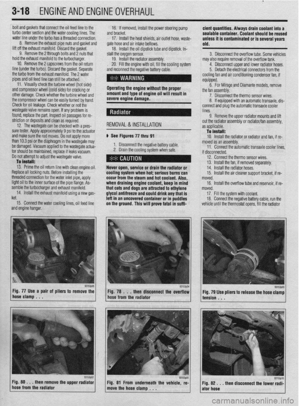
Fig. 77 Use a pair of pliers to remove the
Fig. 78 . . .
then disconnect the overflow
hose clamp . . .
hose from the radiator may also require removal of the overflow tank.
4. Disconnect upper and lower radiator hoses.
5. Detach the electrical connectors from the
cooling fan and air conditioning condenser fan, if
equipped.
6. For Mirage and Diamante models, remove
the fan assembly.
7. Disconnect the therm0 sensor wires,
8. If equipped with an automatic transaxle, dis-
connect and plug the automatic transaxle cooler
lines.
9. Remove the upper radiator mounts and lift
out the radiator assembly or radiator/fan assembly,
as applicable.
To install:
10. Install the radiator or radiator and fan, if re-
moved as an assembly.
11. Connect the automatic transaxle cooler lines
if disconnected.
12. Connect the therm0 sensor wires,
13. Install the fan, if removed separately.
14. Install the radiator hoses.
15. Install the air cleaner support bracket, if re-
noved.
16. Install the overflow tube and reservoir, if re-
noved.
17. Fill the system with coolant.
18. Connect the negative battery cable, run the
vehicle until the thermostat opens, fill the radiator
93153003 Fig. 79 Use pliers to release the hose clamp
tension . . .
Fig. 80 . . .
then remove the upper radiator
hose from the radiator Fig. 81 From underneath the vehicle, re-
move the hose clamp , . . ”
then disconnect the lower radi- Fig. 82 . . .
ator hose
Page 81 of 408
.
3-20 ENGINEANDENGINEOVERHAUL
Never open, service or drain the radiator or
cooling system when hot; serious burns can
occur from the steam and hot coolant. Also,
when draining engine coolant, keep in mind
that cats and dogs are attracted to ethylene
glycol antifreeze and could drink any that is
left in an uncovered container or in puddles
on the ground. This will prove fatal in suffi-
cient quantities. Always drain coolant into a
sealable container. Coolant should be reused
unless it is contaminated or is several years
old.
3. Remove the overflow hose and disconnect
the upper radiator hose.
*It is recommended that each clamp be
matchmarked to the hose. Observe the marks
and reinstall the clamps exactly when rein-
stalling the radiator.
4. If equipped with an automatic transaxle, re-
move and plug the fluid cooler hoses.
5. Unplug the electrical connector(s) from the
coolant fan motor.
6. Remove the mounting bolts, then remove the
fan and shroud assembly from the vehicle.
7. Remove the fan blade retainer nut from the
shaft on the fan motor and separate the fan from the
motor.
8. Remove the motor to shroud attaching
screws and the motor from the shroud.
To tnstall: 9. Install the motor to the shroud and secure
with the mounting bolts.
10. Install the remaining components in the re-
verse order of removal.
11. Fill the coohng system. Connect the negative
battery cable and check the cooling fan for proper op-
eration.
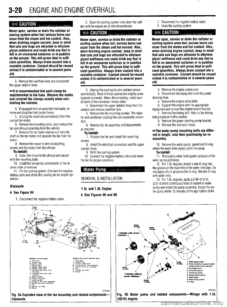
Diamante
# See Figure 94
1. Disconnect the negative battery cable 2. Drain the cooling system only when the radi-
ator and the engine are at safe temperatures. 1. Disconnect the negative battery cable
2. Drain the cooling system.
Never open, service or drain the radiator or
cooling system when hot; serious burns can
occur from the steam and hot coolant. Also,
when draining engine coolant, keep in mind
that cats and dogs are attracted to ethylene
glycol antifreeze and could drink any that is
left in an uncovered container or in puddles
on the ground. This will prove fatal in suffi-
cient quantities. Always drain coolant into a
sealable container. Coolant should be reused
unless it is contaminated or is several years
old.
3. Unplug the cooling fan and radiator sensor
connector(s). Most of these connectors employ a wa-
terproof connector. When disconnecting, make sure
all parts of the connector remain intact.
4. Disconnect the upper radiator hose from the
radiator and remove overflow tank.
5. Remove the fan mounting screws. The radia-
tor and condenser cooling fans are separately remov-
able.
6. Remove the fan assembly and disassemble
Never open, service or drain the radiator or
cooling system when hot; serious burns can
occur from the steam and hot coolant. Also,
when draining engine coolant, keep in mind
that cats and dogs are attracted to ethylene
glycol antifreeze and could drink any that is
left in an uncovered container or in puddles
on the ground. This will prove fatal in suffi-
cient quantities. Always drain coolant into a
sealable container. Coolant should be reused
unless it is contaminated or is several years
old.
3. Remove the engine undercover.
4 Disconnect the clamp bolt from the power
steering hose.
5. Remove the engine drive belts.
6. Support the engine with the appropriate
equipment and remove the engine mount bracket.
7. Remove the timing belt Reier to the timing
belt procedure in this section
8 Remove the power steering pump bracket.
9. Remove the alternator brace.
as required.
To install: 7. Posrtion the fan and install the mounting
screws
*The water pump mounting bolts are differ-
ent in length, note their positioning for re-
assembly.
8 Install the electrical connectors and the upper
radiator hose.
9. Refill the cooling system.
IO. Connect the negative battery cable and check
the fan for orooer ooeration. 10. Remove the water pump, gasket and O-ring
where the water inlet pipe(s) joins the pump.
To install: 11, Thoroughly clean both gasket surfaces of the
water oumo and block.
12. For 1.5L engines, install a new O-ring into
the groove on the front end of the water inlet pipe. Do
not apply oils or grease to the O-ring. Wet the O-ring
with water only
13. For 1.8L engines, apply a 0.09-0.12 in.
(2.5-3 Omm) continuous bead of sealant to water
pump and rnstall the pump assembly. Install the wa-
ter pump within 15 minutes of the applrcation of the
REMOVAL & INSTALLATION
1.5L and 1.8L Engine
) See Figures 95 and 98
7923PGO :ig. 94 Exploded view of the fan mounting and related components- Fig. 95 Water pump and related components-Mirage with 1.51
liamante (4615) engine
Page 145 of 408
4-2 DRIVEABILITYAND EMISSIONS CONTROLS
OPERATION
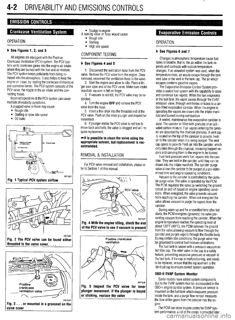
p See Figures 1, 2, and 3
All engines are equipped with the Positive
Crankcase Venhlation (PCV) system. The PCV sys-
tem vents crankcase gases into the engine air intake
where they are burned with the fuel and air mrxture.
The PCV system keeps pollutants from being re-
leased into the atmosphere It also helps to keep the
engine 011 clean, by ridding the crankcase of moisture
and corrosive fumes. The PCV system consists of the
PCV valve, the nipple in the air intake and the con-
necting hoses.
Incorrect operation of the PCV system can cause
multiple driveability symptoms.
A plugged valve or hose may cause’
l Rough Idle l Stalling or slow idle speed l Oil leaks
tT9574goi Fig. 1 Typical PCV system airflow
89574g0r5 Fig. 3 . . .
or mounted in a grommet on the
valve cover
l Sludge in en ine
A leakrng valve or ose would cause: i?
l Rough idle l Stalling l High idle speed
p See Figures 4 and 5
1. Disconnect the ventilation hose from the PCV
valve. Remove the PCV valve from the engine Once
removed, reconnect the ventilation hose to the valve.
2. Start the engine and allow to idle. Place a fin-
ger over open end of the PCV valve. Make sure intake
manifold vacuum is felt on finger.
3. If vacuum is not felt, the PCV valve may be re-
stricted.
4. Turn the engine
OFF and remove the PCV
valve from the hose.
5. Insert a thin stick into the threaded end of the
PCV valve. Push on the inner plunger and inspect for
movement.
6. If plunger inside the PCV valve is not free to
move back and forth, the valve is clogged and WIII re-
quire replacement.
*It is possible to clean the valve using the
appropriate solvent, but replacement is rec-
ommended.
REMOVAL&INSTALLATION
For PCV valve removal and installation, please re-
fer to Section 1 of this manual.
89574QO’ Fig. 4 With the engine idling, check the end
of the PCV valve to see if vacuum is present
Positive crankcase
ventilation
89574go6 Fig. 5 Inspect the PCV valve for inner
plunger movement. If the plunger is bound
or sticking, replace the valve OPERATION
p See Figures 6 and 7
Changes in atmospheric temperature cause fuel
tanks to breathe, that is, the air within the tank ex-
pands and contracts with outside temperature
changes. If an unsealed system was used, when the
temperature rises, air would escape through the tank
vent tube or the vent in the tank cap. The air which
escapes contains gasoline vapors.
The Evaporative Emission Control System pro-
vides a sealed fuel system with the capability to store
and condense fuel vapors. When the fuel evaporates
in the fuel tank, the vapor passes through the EVAP
emission valve, through vent hoses or tubes to a car-
bon filled evaporative canister. When the engine is
operahng the vapors are drawn into the intake mani-
fold and burned during combustion.
A sealed, maintenance free evaporative canister is
used The canister is filled wrth granules of an acti-
vated carbon mixture. Fuel vapors entering the canis-
ter are absorbed by the charcoal granules. A vent cap
is located on the top of the canister to provide fresh
air to the canister when it is being purged. The vent
cap opens to provide fresh air into the canister, which
circulates through the charcoal, releasing trapped va-
pors and carrying them to the engine to be burned.
Fuel tank pressure vents fuel vapors into the can-
ister. They are held in the canister until they can be
drawn into the intake manifold. The canister purge
valve allows the canister to be purged at a pre-deter-
mined time and engine operating conditions.
Vacuum to the canister is controlled by the canis-
ter purge valve. The valve IS operated by the PCM.
The PCM regulates the valve by switching the ground
circuit on and off based on engine operating condi-
tions When energized, the valve prevents vacuum
from reaching the canister. When not energized the
valve allows vacuum to purge the vapors from the
canister.
During warm up and for a specified time after hot
starts, the PCM energizes (grounds) the valve pre-
venting vacuum from reaching the canrster. When the
engine temperature reaches the operating level of
about 120°F (49°C) the PCM removes the ground
from the valve allowing vacuum to flow through the
canister and purges vapors through the throttle body.
During certain Idle conditions, the purge valve may
be grounded to control fuel mixture calibrations.
The fuel tank is sealed with a pressure-vacuum re-
lief filler cap. The relief valve in the cap is a safety
feature, preventing excessive pressure or vacuum in
the fuel tank. If the cap is malfunctioning, and needs
to be replaced, ensure that the replacement is the
identical cap to ensure correct system operation,
OBD-II EVAP System Monitor
Some models have added system components
due to the EVAP system monitor incorporated in the
OBD-II engrne control system. A pressure sensor is
mounted on the fuel tank which measures pressure
inside the tank, and a purge flow sensor measures
the flow of the gases from the canister into the en-
gine.
The PCM can store trouble codes for EVAP sys-
tem performance, a list of the codes is provided later
Page 197 of 408
5-10 FUELSYSTEM
1. _
Fuel tank pressure
-
relef vdive
REMOVAL &INSTALLATION
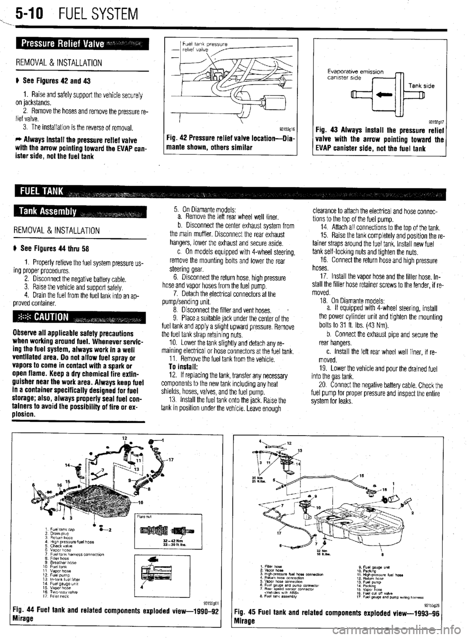
p See Figures 42 and 43
1. Raise and safely support the vehicle securely
on jackstands.
2. Remove the hoses and remove the pressure re-
lief valve.
3. The installation is the reverse of removal.
c, Always install the pressure relief valve
with the arrow pointing toward the EVAP can-
ister side, not the fuel tank 1 mame shown, others similar g3155g” Fig 42 Pressure relief valve location-llia
I I
Evaporatwe emlsslon
canister side
Tank side
+k
93155gt7 Fig. 43 Always install the pressure relief
valve with the arrow pointing toward the
EVAP canister side, not the fuel tank
REMOVAL&INSTALLATION
p See Figures 44 thru 58
1. Properly relieve the fuel system pressure us-
ing proper procedures.
2. Disconnect the negative battery cable.
3. Raise the vehicle and support safelv.
4. Drain the fuel from the fuel tank into an
ap- proved container.
Observe all applicable safety precautions
when working around fuel. Whenever servic-
ing the fuel system, always work in a well
ventilated area. Do not allow fuel spray or
vapors to come in contact with a spark or
open flame. Keep a dry chemical fire extin-
guisher near the work area. Always keep fuel
in a container specifically designed for fuel
storage; also, always properly seal fuel con-
tainers to avoid the possibility of fire or ex-
plosion.
5. On Diamante models:
a. Remove the left rear wheel well liner.
b Disconnect the center exhaust system from
the main muffler. Disconnect the rear exhaust
hangers, lower the exhaust and secure aside.
c. On models equipped with 4-wheel steering,
remove the mounting bolts and lower the rear
steering gear.
6. Disconnect the return hose, high pressure
hose and vapor hoses from the fuel pump.
7. Detach the electrical connectors at the
pump/sending unit.
8. Disconnect the filler and vent hoses.
s
9. Place a suitable jack under the center of the
fuel tank and apply a slight upward pressure. Remove
the fuel tank strap retaining nuts.
10. Lower the tank slightly and detach any re-
maining electrical or hose connectors at the fuel tank.
11. Remove the fuel tank from the vehicle.
To install: 12. If replacing the tank, transfer any necessary
components to the new tank including any heat
shields, hoses, valves, and the fuel pump.
13. Install the fuel tank onto the jack. Rarse the
tank in position under the vehicle. Leave enough
Tg. 44 Fuel tank and related components exploded view-1990-92
mirage
clearance to attach the electrical and hose connec-
tions to the top of the fuel pump.
14. Attach all connectrons to the top of the tank.
15. Raise the tank completely and position the re-
tainer straps around the fuel tank. Install new fuel
tank self-locking nuts and tighten the nuts.
16. Connect the return hose and high pressure
hoses.
17. Install the vapor hose and the filler hose. In-
stall the filler hose retainer screws to the fender, if re-
moved.
18. On Diamante models:
a. If equipped with 4-wheel steering, install
the power cylinder unit and tighten the mounting
bolts to 31 ft. Ibs. (43 Nm).
b. Connect the exhaust pipe and secure the
rear hangers.
c. Install the left rear wheel well liner, if re-
moved.
19. Lower the vehicle and pour the drained fuel
into the gas tank.
20. Connect the negative battery cable. Check the
fuel pump for proper pressure and inspect the entire
system for leaks.
:ig. 45
vlirage Fuel tank and related 93155(12E components exploded view-1993-96
Page 198 of 408
FUELSYSTEM 5-11
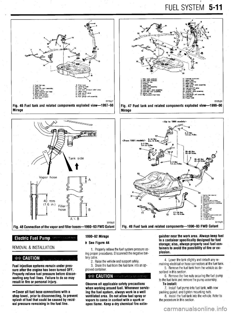
93155gZi Fig. 46 Fuel tank and related components exploded view-1997-98
Mirage
Vapor hose
Filler
hose
Fig. 48 Connection of the vapor and filler hoses-1990-93 FWD Galanl Qt. 49 Fuel tank and related components-1990-93 FWD Galant
1990-92 Mirage
p See Figure 44
REMOVAL &INSTALLATION
Fuel injection systems remain under pres-
sure after the engine has been turned OFF.
Properly relieve fuel pressure before discon-
necting any fuel lines. Failure to do so may
result in fire or personal iniury.
*Cover all fuel hose connections with a
shop towel, prior to disconnecting, to prevent
splash of fuel that could be caused by resid-
ual pressure remaining in the fuel line. Fig. 47 Fuel tank and related components exploded view-1999-00
1. Properly relieve the fuel system pressure us-
ing proper procedures. Disconnect the negative bat-
tery cable
2. Raise the vehicle and support safely.
3.
Dram the fuel from the fuel tank Into an ap-
proved container.
Observe all applicable safety precautions
when working around fuel. Whenever servic-
ing the fuel system, always work in a well
ventilated area. Do not allow fuel spray or
vapors to come in contact with a spark or
open flame. Keep a dry chemical fire extin- guisher near the work area. Always keep fuel
in a container specifically designed for fuel
storage; also, always properly seal fuel con-
tainers to avoid the possibility of fire or ex-
plosion.
4. Lower the tank slightly and detach any re-
maining electrical or hose connectors at the fuel tank.
5. Remove the fuel tank from the vehicle as de-
scribed In this section.
6 Remove the five nuts securing the fuel pump
to the fuel tank and remove the pump assembly.
To install:
7. Install fuel pump into fuel tank, with new
packing gasket, and tighten mounting nuts.
8. Install the fuel tank into the vehrcle. Refer to
the procedure in this section.
Page 199 of 408
5-12 FUELSYSTEM
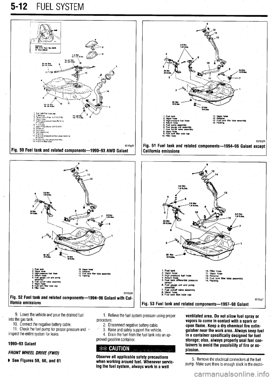
Fig. 50 Fuel tank and related components-1990-93 AWD Galant
:ig. 52 Fuel tank and related components-1994-96 Galant with Cal-
fornia emissions
9. Lower the vehicle and pour the drained fuel
into the gas tank. 1. Relieve the fuel system pressure using proper
procedure. ventilated area. Do not allow fuel spray or
10. Connect the negative battery cable.
11. Check the fuel pump for proper pressure and 2. Disconnect negative battery cable. vapors to come in contact with a spark or
J
inspect the entire system for leaks, 3. Raise and safely support the vehicle. open flame. Keep a dry chemical fire extin-
4. Drain the fuel from the fuel tank Into an ap- guisher near the work area. Always keep fuel
in a container specifically designed for fuel
1990-93 Galant
FRONT WHEEL DRIVE (FWD)
e See Figures 59, 60, and 61
proved gasoline container. storage; also, always properly seal fuel con-
tainers to avoid the possibility of fire or ex-
plosion.
Observe all applicable safety precautions
when working around fuel. Whenever servic-
ing the fuel system, always work in a well
5. Remove the electrical connectors at the fuel
pump. Make sure there is enough slack in the electri-
Page 201 of 408
.
5-14 FUEL SYSTEM
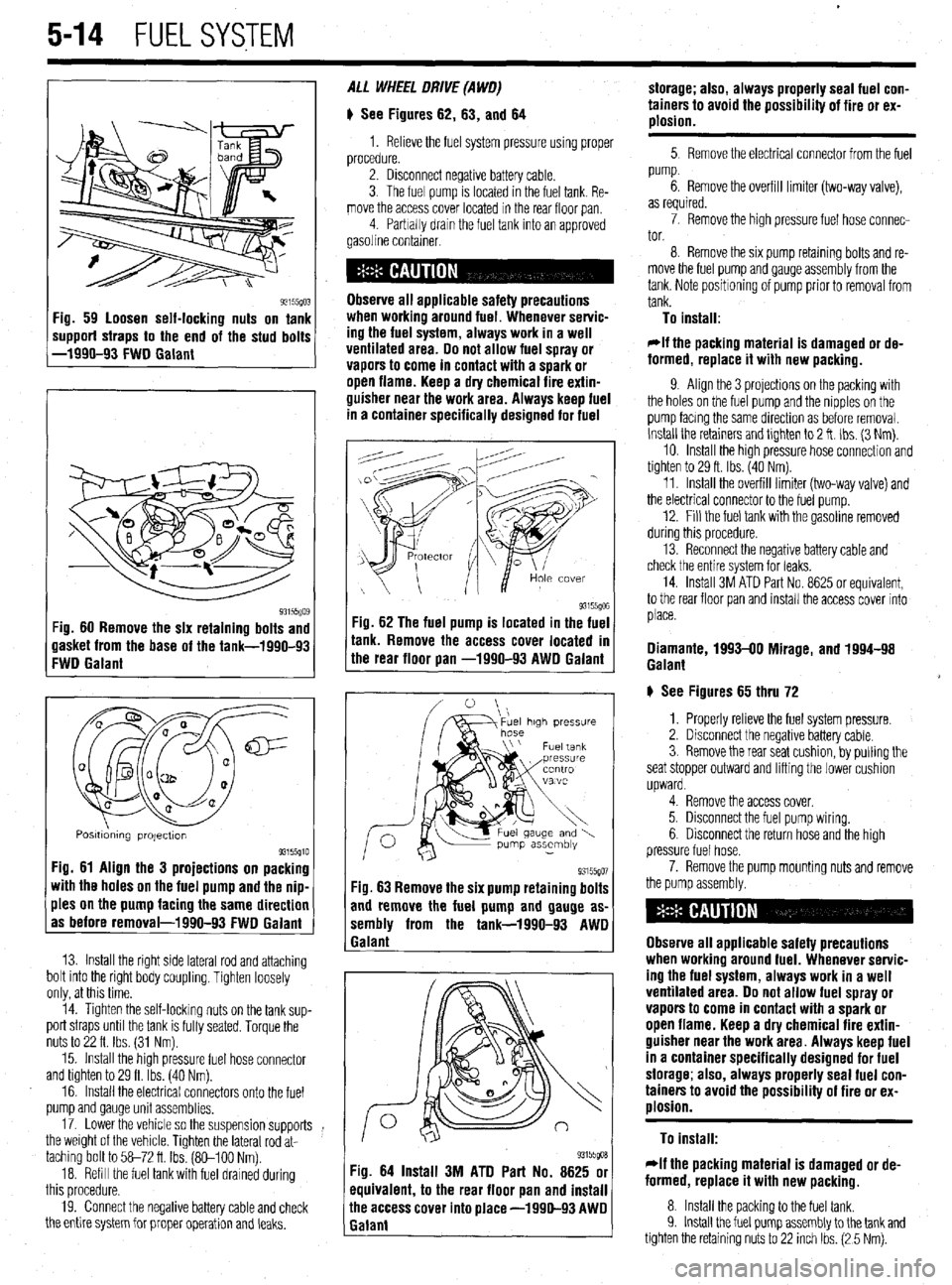
93155(10: ‘ig. 59 loosen self-locking nuts on tank
mpporf straps to the end of the stud bolts
-1990-93 FWD Galant
93i55Qo$ :ig. 60 Remove the six retaining bolts and
lasket from the base of the tank-1990-93
:WD Galant
Q m
0 a
cl@=
u a-
a al2
0
0
Q
a a
Posmdmng projectton 93155910 Fig. 61 Align the 3 projections on packing
with the holes on the fuel pump and the nip-
ples on the pump facing the same direction
as before removal-1990-93 FWD Galant
13. Install the right side lateral rod and attaching
bolt into the right body coupling. Tighten loosely
only, at this time.
14. Tighten the self-locking nuts on the tank sup-
port straps until the tank is fully seated. Torque the
nuts to 22 ft. Ibs. (31 Nm).
15. Install the high pressure fuel hose connector
and tighten to 29 ft. Ibs. (40 Nm).
16. Install the electrical connectors onto the fuel
pump and gauge unit assemblies.
17. Lower the vehicle so the suspension supports
the weight of the vehicle. Tighten the lateral rod at-
taching bolt to 58-72 ft Ibs. (So-100 Nm).
18. Refill the fuel tank with fuel drained during
this procedure.
19. Connect the negative battery cable and check
the entire system for proper operation and leaks. ALL WHEEL DRIVE (A WO)
# See Figures 62, 63, and 64
1. Relieve the fuel system pressure using proper
procedure.
2. Disconnect negative battery cable.
3. The fuel pump is located in the fuel tank. Re-
move the access cover located in the rear floor pan
4 Parbally drain the fuel tank into an approved
gasoline container.
Observe all applicable safety precautions
when workina around fuel. Whenever servic-
ing the fuel system, always work in a well
ventilated area. Do not allow fuel spray or
vapors to come in contact with a spark or
open flame. Keep a dry chemical fire extin-
guisher near the work area. Always keep fuel
in a container specifically designed for fuel
-ig. 62 The fuel pump is located in the fuel
r
ank. Remove the access cover located m
he rear floor pan -1990-93 AWD Galant
93155go7 Fig. 63 Remove the six pump retaining bolts
and remove the fuel pump and gauge as-
sembly from the tank-1990-93 AWD
1 Galant
93155goa Fig. 64 Install 3M ATD Part No. 8625 or
equivalent, to the rear floor pan and install
ihe access cover into place -1990-93 AWD
Ealant storage; also, always properly seal fuel con-
tainers to avoid the possibility of fire or ex-
plosion.
5 Remove the electrical connector from the fuel
pump.
6. Remove the overfill limiter (two-way valve),
as required.
7. Remove the high pressure fuel hose connec-
tor.
8. Remove the six pump retaming bolts and re-
move the fuel pump and gauge assembly from the
tank. Note positioning of pump prior to removal from
tank.
To install:
*If the packing material is damaged or de-
formed, replace it with new packing.
9. Align the 3 projections on the packing with
the holes on the fuel pump and the nipples on the
pump facmg the same direction as before removal.
Install the retainers and tlghten to 2 ft. Ibs. (3 Nm).
10. Install the high pressure hose connection and
tighten to 29 ft. Ibs. (40 Nm).
11. Install the overfill limiter (two-way valve) and
the electrical connector to the fuel pump.
12. Fill the fuel tank with the gasoline removed
during this procedure.
13. Reconnect the negative battery cable and
check the entire system for leaks.
14. Install 3M ATD Part No. 8625 or equivalent,
to the rear floor pan and install the access cover into
place.
Diamante, 1993-00 Mirage, and 1994-98
Galant
# See Figures 65 thru 72
1. Properly relieve the fuel system pressure.
2. Disconnect the negative battery cable.
3. Remove the rear seat cushion, by pulling the
seat stopper outward and lifting the lower cushion
upward.
4. Remove the access cover.
5. Disconnect the fuel pump wiring.
6. Disconnect the return hose and the high
pressure fuel hose.
7. Remove the pump mounting nuts and remove
the pump assembly.
Observe all applicable safety precautions
when working around fuel. Whenever servic-
ing the fuel system, always work in a well
ventilated area. Do not allow fuel spray or
vapors to come in contact with a spark or
open flame. Keep a dry chemical fire extin-
guisher near the work area. Always keep fuel
in a container specifically designed for fuel
storage; also, always properly seal fuel con-
tainers to avoid the possibility of fire or ex-
plosion.
To install:
rlf the packing material is damaged or de-
formed, replace it with new packing.
8. Install the packing to the fuel tank.
9. Install the fuel pump assembly to the tank and
tighten the retaining nuts to 22 inch Ibs. (2 5 Nm).