ECU MITSUBISHI DIAMANTE 1900 Repair Manual
[x] Cancel search | Manufacturer: MITSUBISHI, Model Year: 1900, Model line: DIAMANTE, Model: MITSUBISHI DIAMANTE 1900Pages: 408, PDF Size: 71.03 MB
Page 13 of 408
l
l-14 GENERALINFORMATIONAND MAINTENANCE
Proper maintenance and tune-up is the key to long
and trouble-free vehicle life, and the work can yield
its own rewards. Studies have shown that a properly
tuned and maintained vehicle can achieve better gas
mileage than an out-of-tune vehicle. As a conscien-
tious owner and driver, set aside a Saturday morning,
say once a month, to check or replace items which
could cause major problems later. Keep your own
personal log to jot down which services you per-
formed, how much the parts cost you, the date, and
the exact odometer reading at the time. Keep all re-
selfer, these receipts are the only proof you have that ceipts for such items as engine oil and filters, so that
they may be referred tp in case of related problems or
to determine operating expenses. As a do-it-your- the required maintenance was performed. In the event
of a warranty problem, these receipts will be invalu-
able.
The literature provided with your vehicle when it
was originally delivered includes the factory recom-
mended maintenance schedule. If you no longer have
this literature, replacement copies are usually avail-
able from the dealer. A maintenance schedule is pro-
vided later in this section, in case you do not have
the factory literature. *
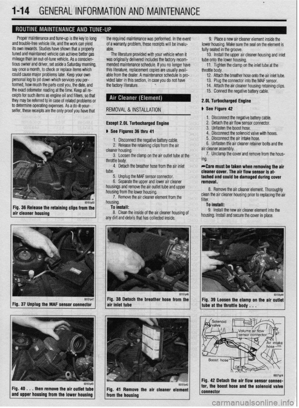
REMOVAL &INSTALLATION
Except 2.gL Turbocharged Engine
b See Figures 36 thru 41 9. Place a new air cleaner element inside the
lower housing. Make sure the seal on the element is
fully seated in the groove.
10. Install the upper air cleaner housing and inlet
tube onto the lower housing.
11. Tighten the clamp on the inlet tube at the
throttle body.
12. Attach the breather hose onto the air inlet tube.
13. Plug the connector into the MAF sensor.
14. Attach the air cleaner housing retaining clips.
15. Connect the negative battery cable.
2.DL Turbocharged Engine
b See Figure 42
1. Disconnect the negative battery cable.
2. Detach the air flow sensor connector.
3. Unfasten the boost hose.
4. Disconnect the solenoid valve with hoses.
93151p50 Fig. 36 Release the retaining clips from the
air cleaner housing
r3151p47 Fig. 37 Unplug the MAF sensor connector
Fig. 49
. . . then remove the air outlet tube
and upper housing from the lower housing 1. Disconnect the negative battery cable. 5. Disconnect the air intake hose.
2. Release the retaining clips from the air 6. Unfasten tie air cleaner retainer bolts and the
cleaner housing. air cleaner assembly.
3. Loosen the clamp on the air outlet tube at the 7. Unclamp the cover and remove from the hous-
throttle body. ing.
4. Detach the breather hose from the air inlet
tube. *Care must be taken when removing the air
cleaner cover. The air flow sensor is at-
5. Unplug the MAF sensor connector.
6. Separate the upper and lower air cleaner tached and could be damaged during cover
removal.
housings and remove the air outlet tube and upper
housing from the lower housing.
7. Remove the air cleaner element from the
housing.
To install:
8. Clean the inside of the air cleaner housing of
any dirt and debris that has collected inside. 8. Remove the air cleaner element. Thoroughly
clean the air cleaner housing prior to replacing the air
filter.
To install:
9. Install the new air cleaner element into the
housing. Install and secure the cover in place.
Fig. 38 Detach the breather hose from the
air tniet tube
Fig. 41 Remove the air cleaner element
from the housing Fig. 39 Loosen the clamp on the air outlet
tube at the throttle body . . .
Fig. 42 Detach the air flow sensor connec-
tor, the boost hose and the solenoid valve
connector
Page 14 of 408
GENERALINFORMATIONAND MAINTENANCE l-15
10. install the air cleaner assembly and the re- *Wrap shop towels around the fitting that is
tainer bolts. being dtsconnected to absorb residual fuel in
11. Connect the air intake hose. the lines. 9. While holding the fuel filter nut with aback-
up wrench, tighten the banjo bolt to 22 ft. Ibs. (30
Nm). Tighten the flare nut to 25 ft. Ibs. (35 Nm), with
12. Attach the solenoid valve.
4. Cover the hose connection with shop towels to a back-up wrench on the nut.
13. Connect the boost hose.
14. Attach the air flow sensor connector. prevent any splash of fuel that could be caused by 10. Tighten the filter mounting bolts to 10 ft. Ibs.
residual pressure in the fuel pipe line. Hold the fuel (14 Nm).
15. Connect the negative battery cable. 11.
filter nut securely with a backup wrench, then remove Connect the negative battery cable. Turn the
REMOVAL &INSTALLATION the banjo bolt on the engine feed line. Disconnect the
high-pressure fuel line from the filter. Remove and
discard the gaskets.
5. While holding the fuel filter nut securely with a
back-up wrench, loosen the filter feed pipe flare nut key to the ON position to pressurize the fuel system
and check for leaks.
12. If repairs of a leak are required, remember to
release the fuel pressure before opening the fuel sys-
tern.
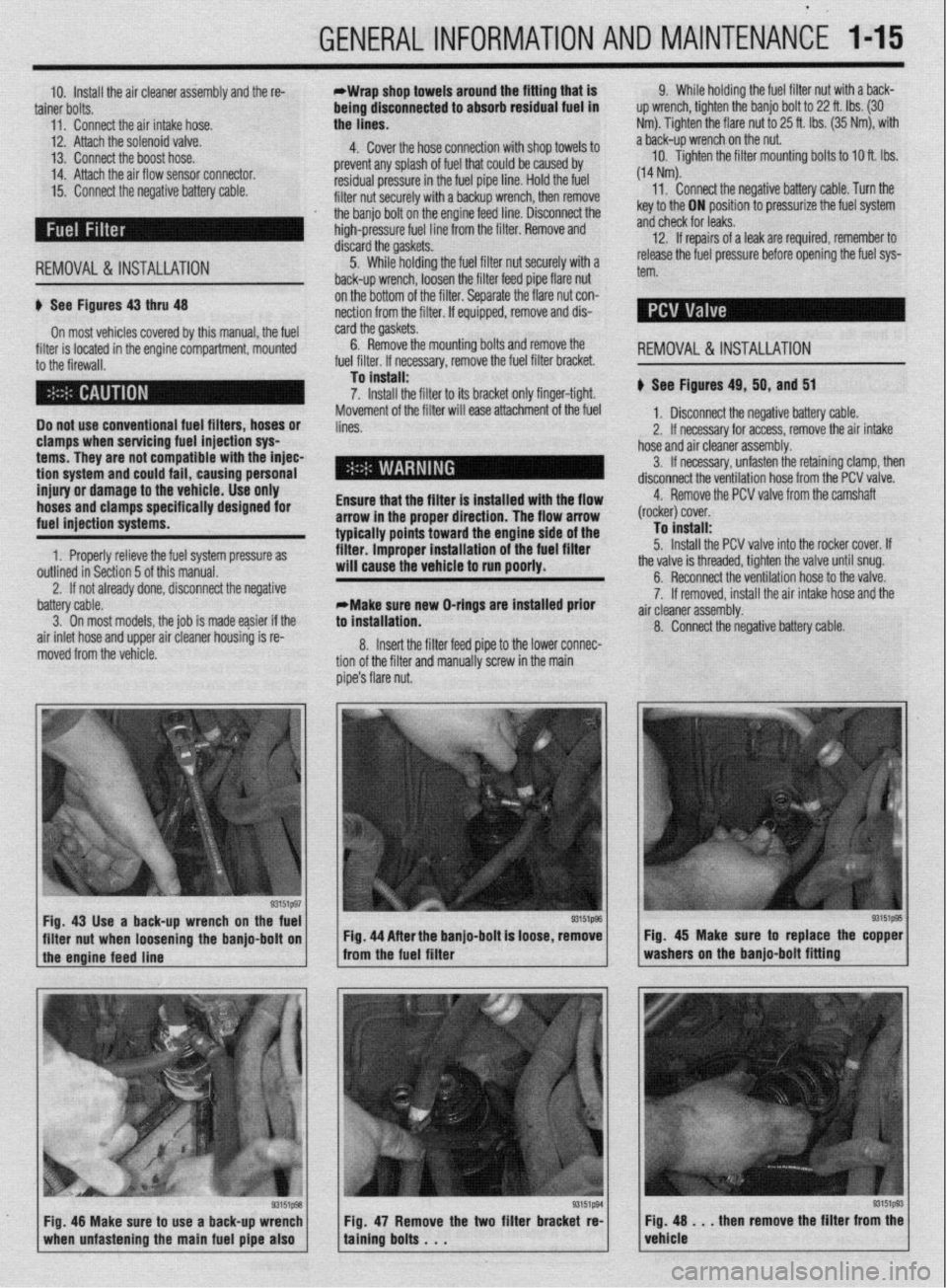
u See Figures 43 thru 48
On most vehicles covered by this manual, the fuel
filter is located in the engine compartment, mounted
to the firewall.
Do not use conventional fuel filters, hoses or
clamps when servicing fuel injection sys
terns. They are not compatible with the injec-
tion
system and could fail, causing personal
injury or damage to the vehicle. Use only
hoses and clamps specifically designed for
fuel injection systems.
1. Properly relieve the fuel system pressure as
outlined in Section 5 of this manual. on the bottom of the filter. Separate the flare nut con-
nection from the filter. If equipped, remove and dis-
card the gaskets.
6. Remove the mounting bolts and remove
. ,,,. ,.
.a r I,.,< I the
ruer rrrter. II necessary, remove me ruer rrrrer oracket.
To install:
7. Install the filter to its bracket only finger-tight.
Movement of the filter will ease attachment of the fuel
lines.
Ensure that the filter is installed with the flow
arrow in the proper direction. The flow arrow
typically points toward the engine side of the
filter. improper installation of the fuel filter
will cause the vehicle to run poorly.
2. If not already done, disconnect the negative REMOVAL&INSTALLATION
u See Figures 49, 50, and 51
1, Disconnect the negative battery cable.
2. If necessary for access, remove the air intake
hose and air cleaner assembly.
3. If necessary, unfasten the retaining clamp, then
disconnect the ventilation hose from the PCV valve.
4. Remove the PCV valve from the camshaft
(rocker) cover.
To install:
5. Install the PCV valve into the rocker cover. If
the valve is threaded, tighten the valve until snug.
battery cable.
3. On most models. the iob is made easier if the
air inlet hose and upper air cleaner housing is re-
moved from the vehicle. *Make sure new O-rings are installed prior
to installation.
8. Insert the filter feed pipe to the lower connec-
tion of the filter and manually screw in the main
pipe’s flare nut. 6. Reconnect the ventilation hose to the valve.
7. If removed, install the air intake hose and the
a .ir cleaner assembly.
8. Connect the negative battery cable.
Fig. 43 Use a back-up wrench on the fuel
I I
93151@3
filter nut when loosening the banjo-bolt on Fig. 44 After the banjo-bolt is loose, remove
I
1 the engine feed line - from the fuel filter
93151p93 Fig. 48 Make sure to use a back-up wrench
1 when unfastening the main fuel pipe also 1 Fig. 47 Remove the two filter bracket re-
taining bolts . . . Fig. 45 Make sure to replace the copper
washers on the banjo-bolt fitting
Fig. 48 . . . then remove the filter from the
vehicle
Page 15 of 408
*
l-16 GENERALINFORMATIONAND MAINTENANCE
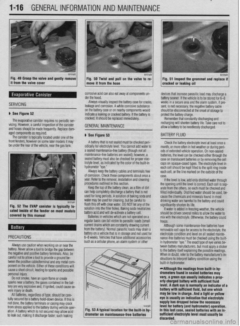
Fig. 49 Grasp the valve and gently remove
Fig. 50 Twist and pull on the valve to re-
it from the valve cover
move it from the hose Fig. 51 Inspect the grommet and replace if
cracked or leaking oil
SERVICING
corrosive acid can also eat away at components un-
der the hood.
Always visually inspect the battery case for cracks,
leakage and corrosion. A white corrosive substance
u See Figure 52
The evaporative canister requires no periodic ser-
vicing. However, a careful inspection of the canister
and hoses should be made frequently, Replace dam- on the battery case or on nearby components would
indicate a leaking or cracked battery. If the battery is
cracked, it should be replaced immediately. GENERALMAINTENANCE '_
devices that increase parasitic load may discharge a
battery sooner. If the vehicle is to be stored for 6-B
weeks in a secure area and the alarm system, if pre-
sent, is not necessary, the negative battery cable
should be disconnected at the onset of storage to
protect the battery charge.
Remember that constantly discharging and
recharging will shorten battery life. Take rare not to
allow a battery to be needlessly discharged.
aged components as required.
The canister is typically located under one of the
front fenders, however on some later models it may
be under the rear of the vehicle, near the gas tank,
r on most models # See Figure 53
A battery that is not sealed must be checked peri-
odically for electrolyte level. You cannot add water to
a sealed maintenance-free battery (though not all
maintenance-free batteries are sealed); however, a
sealed battery must also be checked for proper elec-
trolyte level, as indicated by the color of the built-in
hydrometer “eye.”
Always keep the battery cables and terminals free
of corrosion. Check these components about once a
year. Refer to the removal, installation and cleaning
procedures outlined in this section,
Keep the top of the battery clean, as a film of dirt
can help completely discharge a battery that is not
used for long periods. A solution of baking soda and
water may be used for cleaning, but be careful to
flush this off with clear water. DO NOT let any of the
solution into the filler holes. Baking soda neutralizes
battery acid and will de-activate a battery cell.
Batteries in vehicles which are not operated on a
regular basis can fall victim to parasitic loads (small
BA-ITERY FLUID
Check the battery electrolyte level at least once a
month. or more often in hot weather or during peri-
ods of extended vehicle operation. On non-sealed
batteries, the level can be checked either through the
case on translucent batteries or by removing the cell
caps on opaque-cased types. The electrolyte level in
each cell should be kept filled to the split ring inside
each ceil, or the line marked on the outside of the
case.
If the level is low, add only distilled water through
the opening until the level is correct. Each cell is sep-
arate from the others, so each must be checked and
filled individuallv. Distilled water should be used, be-
cause the chemicals and minerals found in most
drinking water are harmful to the battery and could
significantly shorten its life.
If water is added in freezing weather, the vehicle
should be driven several miles to allow the water to
mix with the electrolyte. Otherwise, the battery could
freeze.
current drains which are constantly drawing current
from the battery). Normal parasitic loads may drain a Although some maintenance-free batteries have
removable cell caos for access to the electrolyte, the
cause a short circuit, leading to sparks and possible
personal injury.
Do not smoke, have an open flame or create
sparks near a battery; the gases contained in the bat-
tery are very explosive and, if ignited, could cause se-
vere injury or death.
All batteries, regardless of type, should be care-
fully secured by a battery hold-down device. If this is
not done, the battery terminals or casing may crack
from stress applied to the battery during vehicle oper-
ation. A battery which is not secured may allow acid
to leak out, making it discharge faster; such leaking m / built-in hydrometer. .
*Although the readings from built-in hy-
drometers found in sealed batteries may
vary, a green eye usually indicates a prop
erly charged battery with sufficient fluid
level. A dark eye is normally an indicator of a
battery wlth sufficient fluid, but one which
may be low in charge. And a light or yellow
eye is usually an indication that electrolyte
supply has dropped below the necessary
tcu1@32 Fig. 53 A typical location for the built-in hv- level for battery (and hydrometer) operation.
drometer on maintenan
ce-free batteries ’ I In this last case. sealed batteries with an in-
sufficient electrolyte level must usually be
’ discarded.
Page 17 of 408
l
1-18 GENERALINFORMATIONAND MAINTENANCE
the clamps and remove the cables, negative cable
first. On batteries with posts on top, the use of a
puller specially made for this purpose is recom-
mended. These are inexoensive and available in most alternator or turn the adjusting bolt to adjust belt ten-
sion. Once the desired value is reached, secure the
bolt or locknut and recheck tension.
d”t” lJdlL> X”lt;>. 31°C LtXlllllldl lJdllt2)’ MLJIC, dlt’ X- cured with a small bolt. ST& I REMOVAL &INSTALLATION
Clean the cable clamps and the battery terminal I
with a wire brush, until all corrosion, grease, etc., is
removed and the metal is shinv. It is esneciallv imnnr-
tant to c
knife is useful nere), since a smart
material or oxidation there will pre Clean the cable clamps and the battery terminal
with a wire brush, until all corrosion, grease, etc., is
removed and the metal is shiny. It is especially impor-
tant to clean the inside of the clamp thoroughly (an old
knife is useful here), since a small deposit of foreign
material or oxidation there will prevent a sound electri-
cal connection and inhibit either starting or charging.
Special tools are available for cleaning these parts,
one type for conventional top post batteries and an-
other type for side terminal batteries. It is also a good
idea to apply some dielectric grease to the terminal, as
this will aid in the prevention of corrosion,
After the clamps and terminals are clean, reinstall
the cables, negative cable last; DO NOT hammer the
clamps onto battery posts. Tighten the clamps se-
curely, but do not distort them. Give the clamps and
terminals a thin external coating of grease after in-
stallation, to retard corrosion.
Check the cables at the same time that the terminals
are cleaned. If the cable insulation is cracked or bro-
ken, or if the ends are frayed, the cable should be re-
placed with a new cable of the same length and gauge.
CHARGING
the cables, negative cable last; DO NOT hammer the
curely, but do not distort them. Give the clamps and
terminals a thin external coating of grease after in-
stallation, to retard corrosion.
Check the cables at the same time that the terminals
are cleaned. If the cable insulation is cracked or bro-
ken, or if the ends are frayed, the cable should be re-
placed with a new cable of the same length and aauae.
CHARGING
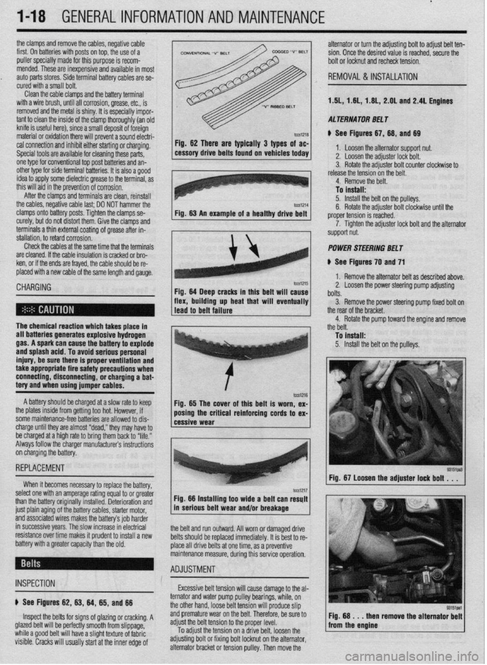
Fig. 62 mere are typically 3 types of ac-
cessory drive belts found on vehicles today 1. Loosen the alternator support nut.
2. Loosen the adjuster lock bolt.
3. Rotate the adjuster bolt counter clockwise to
I .I , . . . * . .
I Tn i”et*ll* Fig. 62 There are typically 3 types of ac-
Fig. 64 Deep cracks in this belt will cause
flex, building up heat that will eventually 11, 1.8L, 2.OL and 2.4L Engines
cal connection and inhibit either starting or charging.
Special tools are available for cleaning these parts,
one type for conventional top post batteries and an-
other type for side terminal batterin, I+ if QI@* 3 nnnd
idea to apply some dielectric grr
this will aid in the prevention of ,,vIIuaIUII.
After the clamps and terminals are clean, reinstall 1.5L, 1.6
AL TERNA TOR BE1 T
e See Figures 67,68, and 69
1. Loosen the alternator support nut.
2. Loosen the adjuster lock bolt.
3. Rotate the adjuster bolt counter clockwise to
release the tension on the belt.
4. Remove the belt.
To install:
5. Install the belt on the pulleys.
6. Rotate the adjuster bolt clockwise until the
proper tension is reached.
7. Tighten the adjuster lock bolt and the alternator
support nut.
POWER STEERING BELT
8 See Figures 70 and 71
1. Remove the alternator belt as described above.
2. Loosen the power steering pump adjusting
bolts.
3. Remove the power steering oumo fixed bolt on
R Rntatn the cxiillrtm hnit A&+,& until the r -r- .- .- ._.. ._ .______
7. Tighten the adjuster lock bolt and the alternator
support nut.
POWER STEERING BELT
1 ..“‘.I ““..Y...Y up II”“. ..IU. ..m.*
1 lead to belt failure V.
I
I
The chemical reaction which takes place in - 1 the rear of the bracket.
4. Rotate the pump toward the engine and remove
the belt.
all batteries generates explosive hydrogen
gas. A spark can cause the battery to explode
and splash acid. To avoid serious personal
injury, be sure there is proper ventilation and
take appropriate fire safety precautions when
connecting, disconnecting, or charging a bat-
tery and when using jumper cables. To fnstall:
5. Install the belt on the pulleys.
A battery should be charged at a slow rate to keep
the plates inside from getting too hot. However, if
some maintenance-free batteries are allowed to dis-
charge until they are almost “dead,” they may have to
be charged at a high rate to bring them back to “life.”
Always follow the charger manufacturers instructions
on charging the battery. 85 The cover of this belt ex-
Fig. is worn,
REPLACEMENT
When it becomes necessary to reolace thn haeoN
‘” yyL’“‘J’ I or oreMer
select one with an amperage rating equal tc .
a ----
than the battery originally installed. Deterioration and
just plain aging of the battery cables, starter motor,
and associated wires makes the battery’s job harder
in successive years. The slow increase in electrical
resistance over time makes it prudent to install a new
battery with a greater capacity than the old. 1 Fig. 67 Loosen the adjuster lock bolt . . .
I ‘-
I -. -_ tm1217 Fig. 66 Installing too wide a belt can resylt
in serious belt wear and/or breakage
the belt and run outward. All worn or damaged drive
belts should be replaced immediately. It is best to re-
place all drive belts at one time, as a preventive
uring this service operation. maintenance measure, d
- ADJUSTMENT : *
INSPECTION Excessive belt tension will cause damage to the al-
e See Figures 62, 83, 64, 65, and 88
Inspect the belts for signs of glazing or cracking. A
glazed belt will be perfectly smooth from slippage,
while a good belt will have a slight texture of fabric
visible. Cracks will usually start at the inner edge of pulley bearings, while, on
It tension will
Droduce slin ternator and water pump
the other hand, loose be
r ------ r
and premature wear on the belt. Therefore, be sure to
adjust the belt tension to the proper level.
To
adjust the tension ’ ’ ’ ” ’ ‘* adjusting bolt or fixing b
alternator bracket or tens on a onve Den. loosen me I Fig. 68 . . . then
from the engine remove the alternator
bolt locknut on the alternator,
iion pulley. Then move the
Page 18 of 408
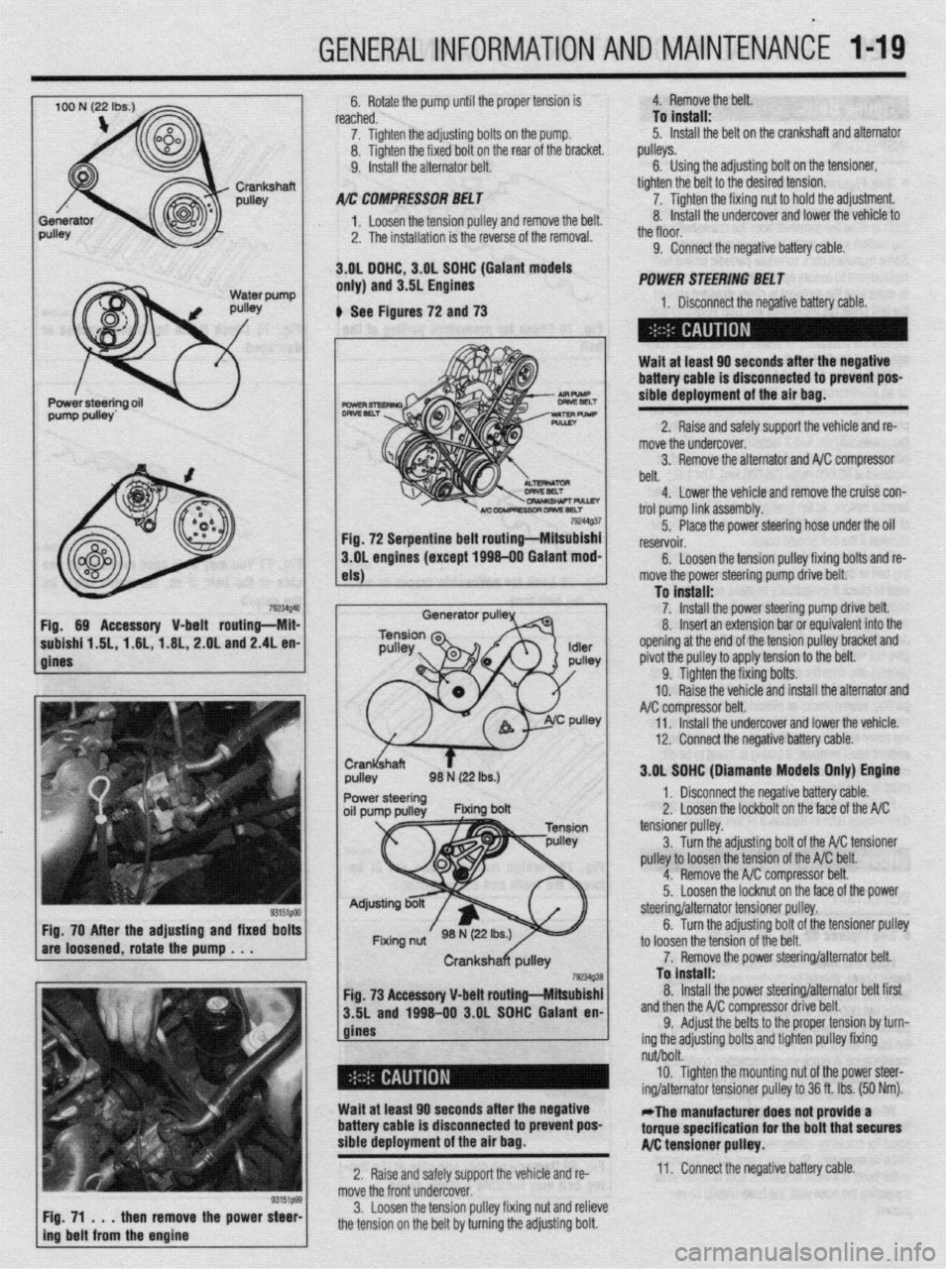
GENERAL INFORMATION AND MAlNTENANdE l-19
792UQ4 Fig. 69 Accessory V-belt routing-Mii
subishf 1.6L, 1.6L,-1.6L, 2.OL and 2.4L en
gines
33151PM Fig. 70 After the adjusting and fixed bolt!
are loosened, rotate the pump . . .
/ F$71t immtl$mm&a the power ::: 6. Rotate the pump until the proper tension is
reached.
7. Tighten the adjusting bolts on the pump.
8. Tighten the fixed bolt on the rear of the bracket.
9. Install the alternator belt.
A/r: COMPRESSOIl BEL f
1. Loosen the tension oullev and remove the belt.
2. The installation is the reverse of the removal.
.3.gL DGHC, 3.OL SOHC (Gaiant models
only) and 3.5L Engines 4. Remove the belt.
To install:
5. Install the belt on the crankshaft and alternator
pulleys.
6. Using the adjusting bolt on the tensioner,
tighten the belt to the desired tension.
7. Tighten the fixing nut to hold the adjustment.
8. Install the undercover and lower the vehicle to
_,
the tloor.
9. Connect the negative battery cable.
POWER SliEERlNG BEL f
6 See Figures 72 and 73 1. Disconnect the neaative batteN cah+P
-I
Wait at least 60 seconds after the negative
battery cable is disconnected to prevent poS-
sibie deployment of the air bag.
2. Raise and safely support the vehicle and re-
mob re the undercover.
3. Remove the alternator and NC compressor
belt.
4. Lower the vehicle and remove the cruise con-
trol oumn link iW%mblV. 79244Q.37
-- I-- r ---- - _I
Fig. 72 Serpentine belt routing-Mitsubishi 5. Place the power steering hose under the oil
reservoir.
3.OL engines (except 1696-00 Galant mod-
6.
Loosen the tension pulley fixing bolts and re-
els)
Generator pulP
1 move the power steering pump drive belt.
To install:
1 7. install the Dower steerina oumu r+r+v~ hp++
8. Insert an extension bar &eoufvaik;;t”f;;id‘he
opening at the end of the tension pulley bracket and
pivot the pulley to apply tension to the belt.
9. Tighten the fixing bolts.
10. Raise the vehicle and install the alternator and
compressor belt.
Il. Install the undercover and lower +hfi vph+r+p
.I,., .VII.“.Y.
12. Connect the negative battery cable.
I 3.OL SGHC (Diamante Models Onivl Enotne
I ,r ” 1. Disconnect the negative battery cable.
2.’ Loosen the lockbolt on the face nf the A/C _ __.- tensioner pulley.
3
Turn the adiustina bolt of the A/C +fincrnner
pulley to loosen the tension of the A/C belt.
4. Remove the A/C compressor belt.
5.
Loosen the locknut on the face of the power
to loosen the tc
7. Remov
Fig. 73 Accessory V-belt routing-Mitsubishi
3.5L and 1996-00 3.OL SOHC Galant en-
gines steering/alternator tensloner pulley.
6. Turn the adjusting bolt of the tensioner pulley
msion of the belt.
‘e the power steering/alternator belt.
To install:
8. Install the power steering/alternator belt first
.* .* . ,^
ssor drive belt. ana tnen tne A/ti compre:
9. Adjust the belts t+
ing the adjusting bolts anu
II~IIWII pueey tlxmg I the proper tension by turn-
A.:-L I-..-.. I,^, .’
nut/bolt.
10. Tighten the mounting nut of the power steer-
ing/alternator tensioner pulley to 36 ft. Ibs. (50 Nm).
Wait at least 60 seconds after the negative
battery cable is disconnected to prevent pos-
sible deployment of the air bag. -The manufacturer does not provide a
torque specification for the bolt that secures
A/C tensioner pulley.
2. Raise and safely support the vehicle and re- 11. Connect the negative battery cable.
move the front undercover.
3. Loosen the tension pulley fixing nut and relieve
the tension on the belt by turning the adjusting bolt.
Page 20 of 408
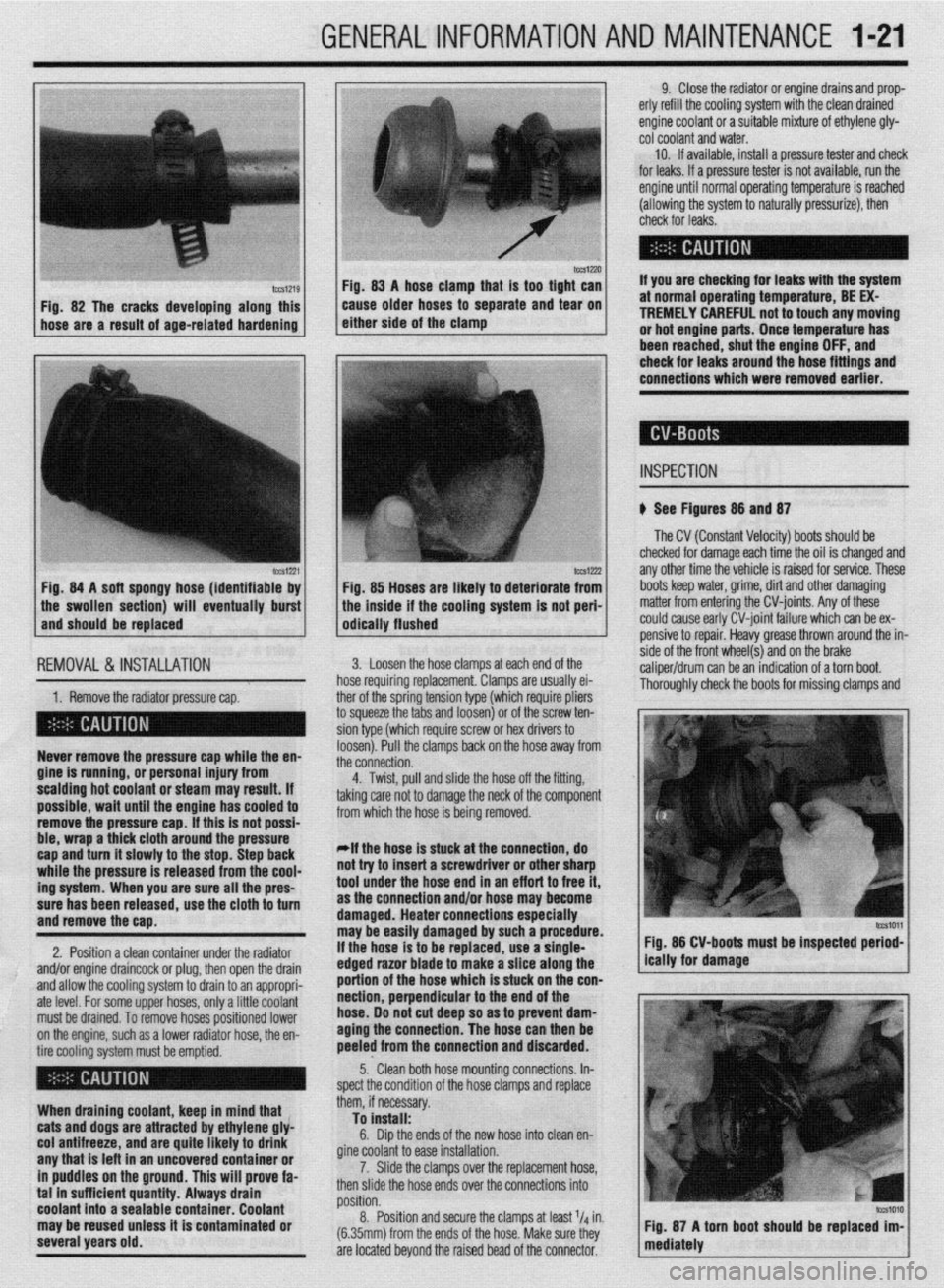
GENERALINFORMATIONAND MAINTENANCE l-21
IWSIZXJ FM. 83 A hose clamn that is taa tiaht can
Fig. 82 The cracks developing along this
hose are a result of age-related hardening caise older hoses td separate and ‘iear on
either side of the clamp
lCCS1221 Fig. 84 A soft spongy hose (identifiable by
1 the swollen section) will eventually burst
and should be replaced
IEMOVAL &,INSTALLATION '
1. Remove the radiator pressure cap. her of the sorina tension tvoe (which reouire oliers
3 squeeze the 6bs and loosenj or of the’screw ten-
ion type (which require screw or hex drivers to
oosen). Pull the clamps back on the hose away from
he connection. Never remove the pressure cap while the en-
gine is running, or personal injury from
scalding hot coolant or steam may result. If
possible, wait until the engine has cooled to
remove the pressure cap. If this is not possi-
ble, wrap a thick cloth around the pressure
cap and turn it slowly to the stop. Step back
while the pressure is released from the cool-
ing system. When you are sure all the pres-
sure has been released, use the cloth to turn
and remove the cao.
2. Position a clean container under the radiator
and/or engine draincock or plug, then open the drain
and allow the cooling system to drain to an appropri-
ate level. For some upper hoses, only a little coolant
must be drained. To remove hoses positioned lower
on the engine, such as a lower radiator hose, the en-
tire cooling system must be emptied.
When draining coolant, keep in mind that
cats and dogs are attracted by ethylene gly-
col antifreeze, and are quite likely to drink
any that is left in an uncovered container or
in puddles on the ground. This will prove fa-
tal in sufficient quantity. Always drain
coolant into a sealable container. Coolant
may be reused unless it is contaminated or
several years old. 9. Close the radiator or engine drains and prop-
erly refill the cooling system with the clean drained
engine coolant or a suitable mixture of ethylene gly-
cot coolant and water.
10. If available, install a pressure tester and check
for leaks. If a pressure tester is not available, run the
engine until normal operating temperature is reached
(allowing the system to naturally pressurize), then
check for leaks.
If you are checking for leaks with the system
at normal operating temperature, BE EX-
TREMELY CAREFUL not to touch any moving
or hot engine parts. Once temperature has
been reached. shut the enaine OFF. and
Fig. 85 Hoses are likely to deteriorate from
the inside if the cooling system is not peri-
odically flushed check for leaks around the-hose fittings and
connections which were removed earlier.
INSPECTION
b See Figures 88 and 87
The CV (Constant Velocity) boots should be
checked for damage each time the oil is changed and
any other time the vehicle is raised for service. These
boots keep water, grime, dirt and other damaging
matter from entering the CV-joints. Any of these
could cause early CV-joint failure which can be ex-
pensive to repair. Heavy grease thrown around the in-
side of the front wheel(s) and on the brake
caliper/drum can be an indication of a torn boot.
Thorouahlv check the boots for missina clamos and 3. Loosen the hose clamps at each end of the
rose requiring replacement. Clamps are usually ei-
4. Twist, pull and slide the hose off the fitting,
sking care not to damage the neck of the component
rom which the hose is being removed.
*If the hose is stuck at the connection, do
lot try to insert a screwdriver or other sharp
ool under the hose end in an eff art to free it,
IS the connection and/or hose may become
lamaged. Heater connections especially
nay be easily damaged by such a procedure.
f the hose is to be replaced, use a single-
!dged razor blade to make a slice along the
lortion of the hose which is stuck on the con-
section, perpendicular to the end of the
lose. 00 not cut deep so as to prevent dam-
aging the connection. The hose can then be
keeled from the connection and discarded. Fig. 86 CV-boots must be inspected period-
5.. Clean both hose mounting connections. In-
,pect the condition of the hose clamps and replace
hem, if necessary.
To install:
6. Dip the ends of the new hose into clean en-
fine coolant to ease installation.
7. Slide the clamps over the replacement hose,
hen slide the hose ends over the connections into
rosition.
8. Position and secure the clamps at least l/d in.
6.35mm) from the ends of the hose. Make sure they
Ire located beyond the raised bead of the connector.
Page 25 of 408
.
1-26 GENERALINFORMATIONAND MAINTENANCE
TDC of the compression stroke. If this happens, the
piston WIII be at the beginning of the power stroke
just as the compressed and ignited air/fuel mixture
forces the piston down and turns the crankshaft. Be-
cause it takes a fraction of a second for the spark
plug to ignite the mixture in the cylinder, the spark
plug must fire a little before the piston reaches TDC.
Otherwise, the mixture will not be completely ignited
as the piston passes TDC and the full power of the
explosion will not be used by the engine.
The timing measurement is given in degrees of
crankshaft rotation before the piston reaches TDC
(BTDC). If the setting for the ignition timing is 10”
BTDC, each spark plug must fire 10 degrees before
each piston reaches TDC. This only holds true, how-
ever, when the engine is at idle speed. The combus-
tion process must be complete by 23”ATDC to main-
tain proper engine performance, fuel mileage, and
low emissions.
As the engine speed increases, the pistons go
faster. The spark plugs have to ignite the fuel even
sooner if it IS to be completely ignited when the pis-
ton reaches TDC. If the ignition is set too far ad-
vanced (BTDC), the ignition and expansion of the fuel
in the cylinder wtll occur too soon and tend to force
the piston down while it is still traveling up. Thus
causes pre ignition or “knockmg and pinging”. If the
ignition spark is set too far retarded, or after TDC
(ATDC), the piston will have already started on its
way down when the fuel is ignited. The piston will be
forced down for only a portion of its travel, resulting
in poor engine performance and lack of power.
Timing marks or scales can be found on the rim of
the crankshaft pulley and the timing cover. The marks
on the pulley correspond to the posrtion of the piston
in the No. 1 cylinder. A stroboscopic (dynamic) tim-
ing light is hooked onto the No. 1 cylinder spark plug
wrre. Every time the spark plug fires, the timing light
flashes. By aiming the light at the timing marks while
the engine is running, the exact position of the piston
within the cylinder can be easily read (the flash of
light makes the mark on the pulley appear to be
standing still). Proper timing is indicated when the
mark and scale are in specified alignment.
When checking timing with the engine run-
ning, take care not to get the timing light
wires tangled in the tan blades and/or drive
belts.
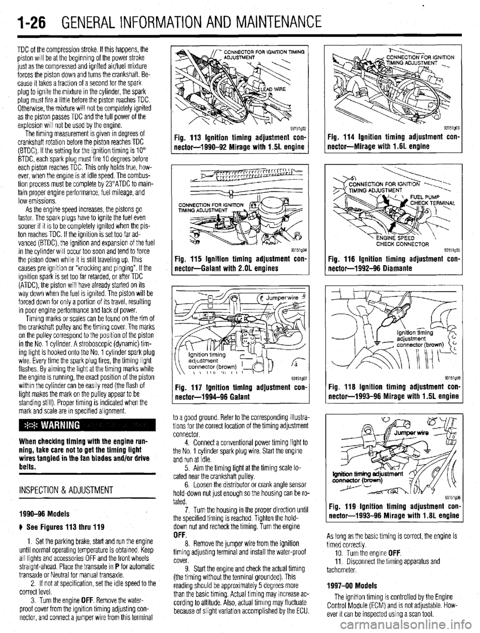
INSPECTION &ADJUSTMENT
1990-96 Models
e See Figures 113 thru 119
1. Set the parking brake, start and run the engine
until normal operating temperature is obtained. Keep
all lights and accessories OFF and the front wheels
straight-ahead. Place the transaxle in
P for automatic
transaxle or Neutral for manual transaxle.
2. If not at specification, set the idle speed to the
correct level.
3. Turn the engine
OFF. Remove the water-
proof cover from the igmtion timing adjusting con-
nector, and connect a jumper wire from this terminal
Fig. 113 Ignition timing adjustment con-
nector-1990-92 Mirage with 1.5L engine
93151QM Fig. 115 Ignition timing adjustment con-
nectar-Galant with 2.OL engines
93151QO1 Fig. 117 Ignition timing adjustment con.
nectar-1994-96 Galant
to a good ground. Refer to the corresponding illustra-
tions for the correct location of the timing adjustment
connector.
4. Connect a conventional power timing light to
the No. 1 cylinder spark plug wire. Start the engine
and run at idle.
5. Aim the timing light at the timing scale lo-
cated near the crankshaft pulley.
6. Loosen the distributor or crank angle sensor
hold-down nut just enough so the housing can be ro-
tated.
7. Turn the housing in the proper direction until
the specified timing is reached. Tighten the hold-
down nut and recheck the timing. Turn the engine
OFF. 8. Remove the jumper wire from the ignition
timing adjusting terminal and install the water-proof
cover.
9. Start the engine and check the actual timing
(the timing without the terminal grounded). This
reading should be approximately 5 degrees more
than the basic timing. Actual timing may increase ac-
cording to altitude. Also, actual timing may fluctuate
because of slight variation accomplished by the ECU.
Fig. 114 Ignition timing adjustment con-
nectar-Miracle with 1.6L enaine
CHECK CONNECTOR 93151QO! Fig. 116 Ignition timing adjustment con.
nectar-1992-96 Oiamante
93151gOB Fig. 116 Ignition timing adjustment con-
nector-1993-96 Mirage with 1.5L engine
Fig. 119 Ignition timing adjustment con-
nector-1993-96 Mirage with 1.6L engine
As long as the basic timing is correct, the engine is
timed correctly.
10. Turn the engine
OFF. 11. Disconnect the timing apparatus and
tachometer.
1997-00 Models
The ignition timing is controlled by the Engine
Control Module (ECM) and is not adjustable. How-
ever it can be inspected using a scan tool.
Page 26 of 408
GENERALINFORMATIONAND MAlNTENANdE I-27
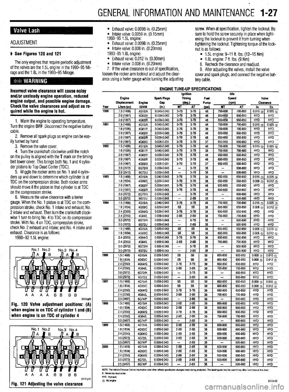
ADJUSTMENT
u See Figures 120 and 121
The only engines that require periodic adjustment
of the valves are the 1.5L engine in the 1990-95 Mi-
rage and the 1.8L in the 1993-95 Mirage.
Incorrect valve clearance will cause noisy
and/or unsteady engine operation, reduced
engine output, and possible engine damage.
Check the valve clearances and adjust as re-
quired while the engine is hot.
1. Warm the engine to operating temperature.
Turn the engine OFF. Disconnect the negative battery
cable.
2. Remove all spark plugs so engine can be eas-
ily turned by hand
3. Remove the valve cover.
4. Turn the crankshaft clockwise until the notch
on the pulley is aligned with the
T mark on the timing
belt lower cover. This brings both No. 1 and 4 cylin-
der pistons to Top Dead Center (TDC).
5. Wiggle the rocker arms on No. 1 and 4 cylin-
ders up and down to determine which cylinder is at
TDC on the compression stroke. Both rocker arms
should move if the piston in that cylinder is at TDC
on the compression stroke.
6. Measure the valve clearance with a feeler
gauge. When the No. 1 piston is at TDC on the com-
pression stroke, check No. 1 intake and
exhaust; No.
2 intake and exhaust. Then turn the crankshaft clock-
wise 1 turn to bring No. 4 to TDC on its compression
stroke. With No. 4 on TDC, compression stroke,
check No. 2 exhaust and intake; and No. 4 intake and
exhaust. Clearance is as follows:
1990-92 1.5L engine:
No.1 No.2
No.3 No.4
when engine is on TDC of cylinder 1 and (B) when engine is on TDC of cylinder 4
No.1 No.2
No.3 No.4
AA AA BB BB
93151g10 Fig. 121 Adjusting the valve clearance
l Exhaust valve: 0.0098 in. (0.25mm) screw. When at specification, tighten the locknut. Be l Intake valve: 0.0059 in. (0.15mm)
1993-95 1.5L engine: sure to hold the screw securely in place when tight-
l Exhaust valve: 0.0098 in. (0.25mm) ening the locknut to prevent it from turning when
* Intake valve: 0.008 in. (0.20mm) tightening the locknut. Tightening torque of the lock-
nut is as follows:
1993-95 1.8L engine:
l Exhaust valve: 0.012 in. (0.30mm) l 1.5L engine: 9-11 ft. Ibs. (12-15 Nm)
l Intake valve: 0.008 in. (0.20mm) l 1.8L engine: 7 ft. Ibs. (9 Nm)
8. Recheck the clearance and readjust.
7. If the valve clearance is out of specification,
9. After adjusting the valves, install the valve
loosen the rocker arm locknut and adjust the clear-
ante using a feeler gauge while turning the adjusting cover and spark plugs, and connect the negative bat-
tery cable.
Engine
ENGINE TUNE-UP SPECIFICATIONS Ignition
Spark Plugs liming
Fuel Idle
Speed Valve
Displacement
Engine
Gap (as.) Pump (rpm)
Clearance
Page 27 of 408
l-28 GENERALINFORMATIONAND MAINTENANCE
may result in skin or eye irritation or frostbite. Al- formed to help maintain the efficiency of the vehicle’s
though low in toxicity (due to chemical stability), in- A/C system. For preventive maintenance, perform the
The idle speed is factory set and usually no ad- halation of concentrated refrigerant fumes is danger- following:
justments are ever necessary. If an adjustment be- ous and can result in death; cases of fatal cardiac
l The easiest and most important preventive
comes necessary, first check that the spark plugs, in- arrhythmia have been reported in people accidentally maintenance for your A/C system is to be sure that it
jectors, idle air control servo and compression subjected to high levels of refrigerant. Some early is used on a regular basis. Running the system for
pressure are all normal. symptoms include loss of concentration and drowsi- five minutes each month (no matter what the season)
Data from various sensors and switches are used ness. + will help ensure that the seals and all internal compo-
by the ECU to determine the proper fuel/air mixture
for optimal engine performance. cGeneraiiy, the limit for exposure is lower nents remain lubricated.
for R-134a than it is for R-12. Exceptional *Some newer vehicles automatically oper-
care must be practiced when handling R- ate the A/C system compressor whenever the
134a. windshield defroster is activated. When run-
Also, refrigerants can decompose at high tempera- ning, the compressor lubricates the A/C sys
tures (near gas heaters or open flame), which may re- tern components; therefore, the A/C system
SYSTEM SERVICE& REPAIR suit in hydrofluoric acid, hydrochloric acid and phos- would not need to be operated each month.
gene (a fatal nerve gas). * In order to prevent heater core freeze-up during
R-12 refrigerant can damage the environment be- A/C operation, it is necessary to maintain proper an-
cause it is a Chlorofluorocarbon (CFC), which has tifreeze protection. Use a hand-held coolant tester
been proven to add to ozone layer depletion, leading (hydrometer) to periodically check the condition of
to increasing levels of UV radiation. UV radiation has the antifreeze in your engine’s cooling system.
been linked with an increase in skin cancer, suppres-
sion of the human immune system, an increase in *Antifreeze should not be used longer than
cataracts, damage to crops, damage to aquatic organ- the manufacturer specifies.
isms, an increase in ground-level ozone, and in- . For efficient operation of an air conditioned ve-
creased global warming. hicle’s cooling system, the radiator cap should have a
R-134a refrigerant is a greenhouse gas which, if holding pressure which meets manufacturers specifi-
allowed to vent into the atmosphere, will contribute to cations. A cap which fails to hold these pressures
global warming (the Greenhouse Effect). should be replaced.
It is usually more economically feasible to have a
l Any obstruction of or damage to the condenser
certified MVAC automotive technician perform A/C configuration will restrict air flow which is essential
system service on your vehicle. Some possible rea- to its efficient operation. It is, therefore, a good rule
sons for this are as follows: to keep this unit clean and in proper physical shape.
l While it is illegal to service an A/C system
without the proper equipment, the home mechanic ti See Figure 122
*it is recommended that the A/C svstem be
serviced by an EPA Section 609 cehified au-
tomotivetechnicfan utilizing a refrigerant re-
covery/recycling machfne.
The do-it-yourselfer should not service his/her
own vehicle’s A/C system for many reasons, includ-
ing legal concerns, personal injury, environmental
damage and cost. The following are some of the rea-
sons why you may decide not to service your own ve-
hicle’s A/C system.
According to the U.S. Clean Air Act, it is a federal
crime to service or repair (involving the refrigerant) a
Motor Vehicle Air Conditioning (MVAC) system for
money without being EPA certified. It is also illegal to
vent R-12 and R-134a refrigerants into the atmos-
phere. Selling or distributing A/C system refrigerant
(in a container which contains less than 20 pounds oi
refrigerant) to any person who is not EPA 609 certi-
fied is also not allowed by law.
State and/or local laws may be more strict than the
federal regulations, so be sure to check with your
state and/or local authorities for further information.
For further federal information on the legality of ser-
vicing your AK system, call the EPA Stratospheric
Ozone Hotline.
*Federal law dictates that a fine of up to
$25,000 may be levied on people convicted
of venting refrigerant into the atmosphere.
Additionally, the EPA may pay up to $10,000
for information or services leading to a crimf
nai conviction of the violation of these laws.
When servicing an A/C system you run the risk of
handling or coming in contact with refrigerant, which
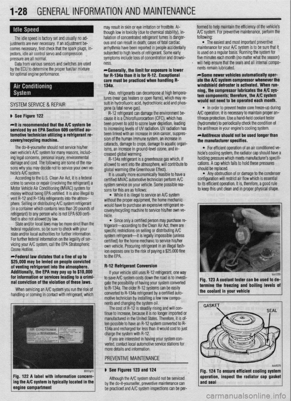
Fig. 122 A label with information concern-
ing the A/C system is typically located in the
engine compartment
f would haveto purchase an expensive refrigerant re-
covery/recycling machine to service his/her own ve-
hicle.
l Since only a certified person may purchase re-
frigerant-according to the Clean Air Act, there are
specific restrictions on selling or distributing A/C
system refrigerant-it is legally impossible (unless
certified) for the home mechanic to service his/her
own vehicle. Procuring refrigerant in an illegal fash-
ion exposes one to the risk of paying a $25,000 fine
to the EPA.
R-12 Refrigerant Conversion
If your vehicle still uses R-12 refrigerant, one
way to save A/C system costs down the road is to invesh-
gate the possibility of having your system converted
to R-134a. The older R-12 systems can be easily
converted to R-134a refrigerant by a certified auto-
motive technician by installing a few new compo-
nents and changing the system oil.
The cost of R-12 is steadily rising and will con-
tinue to increase, because it is no longer imported or
manufactured in the United States. Therefore, it is of-
ten possible to have an R-12 system converted to R-
134a and recharged for less than it would cost to just
charge the system with R-12.
If you are interested in having your system con-
verted, contact local automotive service stations for
more details and information.
u See Figures 123 and 124
Although the A/C system should not be serviced
by the do-it-yourselfer, preventive maintenance can
be practiced and A/C system inspections can be per- Fig. 123 A coolant tester can be used to de-
1 termine the freezing and boiling levels of
the coolant in your vehicle
Fig. 124 To ensure efficient cooling system
operation, inspect the radiator cap gasket
and seal
Page 43 of 408
1-44 GENERALINFORMATIONAND MAINTENANCE
INTERIOR CLEANING
Upholstery
Fabric can usually be cleaned with soapy water or
a proper detergent. For more difficult spots caused by
oil, ice cream, soda, etc., use a fabric cleaner avail-
able at most parts stores. Be sure when purchasing
the cleaner to read the label to ensure it is safe to use
on your type of fabric. A safe method of testing the
cleaner is to apply a small amount to an area usually
unseen, such as under a seat, or other areas. Wart a
while, perhaps even a day to check the spot for fad-
ing, discoloring, etc., as some cleaners will only
cause these problems after they have dried
Leather upholstery requrres special care, it can be
cleaned with a mild soap and a soft cloth. It is recom-
mended that a special leather cleaner be used to
clean but also treat the leather surfaces in your vehi-
cle. Leather surfaces can age quickly and can crack if
not properly taken care of, so it is vital that the leather
surfaces be maintained.
Floor Mats and Carpet
The floor mats and carpet should be vacuumed or
brushed regularly. They can be cleaned with a mild
soap and water. Special cleaners are available to
clean the carpeted surfaces of your vehicle, but take
care in choosing them, and again it is best to test
them in a usually unseen spot.
Dashboard, Console, Door Panels, Etc.
The dashboard, console, door panels, and other
plastic, vinyl, or wood surfaces can be cleaned using
a mild soap and water. Caution must be taken to keep
water out of electronic accessories and controls to
avoid shorts or ruining the components Again spe-
cial cleaners are available to clean these surfaces, as
with other cleaners care must taken in purchasmg
and using such cleaners.
There are protectants available which can treat the
various surfaces in your car giving them a “shiny new
look”, however some of these protectants can cause
more harm than good in the long run. The shine that
is placed on your dashboard attracts sunlight accel-
erating the aging, fading and possibly even cracking
the surfaces. These protectants also attract more dust
to stick to the surfaces they treat, Increasing the cleaning you must do to maintain the appearance of
your vehicle. Personal discretion is advised here.
On most models covered by this manual, the
wheel bearmgs used are sealed units and do not re-
quire routine maintenance. However on some Galant
and Mirage models, the rear wheel bearing do require
periodic repacking. For removal and installation in-
structions, please refer to Section 7 (for rear bear-
ings) or Section 8 (for front bearings).
REPACKING
*Sodium based grease is not compatible
with lithium based grease. Read the package
labels and be careful not to mix the two
types. If there is any doubt as to the type of
grease used, completely clean the old
grease from the bearing and hub before re-
placing.
Before handling the bearings, there are a few
things that you should remember to do and not to do.
DO the following: l Remove all outside dirt from the housing be-
fore exposing the bearing.
l Treat a used bearing as gently as you would a
new one.
l Work with clean tools in clean surroundings. l Use clean, dry gloves, or at least clean, dry
hands.
l Clean solvents and flushing fluids are a must. l Use clean paper when laying out the bearings
to dry.
l Protect drsassembled bearings from rust and
dirt. Cover them up.
l Use clean, lint-free rags to wipe the bearings. l Keep the bearings in oil-proof paper when they
are to be stored or are not in use.
l Clean the inside of the housing before replac-
ing the bearin
Do NOT do he followino: El, l Do not work in dirty sirroundings. l Do not use dirty, chipped or damaged tools. l Do not work on wooden work benches or use
wooden mallets.
l Do not handle bearings with dirty or moist
hands.
l Do not use gasoline for cleaning. Use a safe
solvent.
l Do not spin dry bearings with compressed air.
They will be damaged.
l Do not use cotton waste or dirty cloths to wipe
bearings.
l Do not scratch or nick bearing surfaces. l Do not allow the bearina to come in contact
” with dirt or rust at any time.
The rear wheel bearinas on some Galant and Mi-
rage models require periodic maintenance. A pre-
mium high melting point grease meeting Grade
Multipurpose Grease NLGI Grade #2 or equivalent
must be used. Long fiber type greases must not be
used. This service is recommended every 30,000
miles (48,000 km).
*For information on Wheel Bearing removal
and installation, refer to Section 7 of this
manual.
1. Remove the wheel bearing.
2. Clean all parts in a non-flammable solvent and
let them air dry.
*Only use lint-free rags to dry the bearings.
Never spin-dry a bearing with compressed
air, as this will damage the rollers.
3. Check for excessive wear and damage. Replace
the bearing as necessary.
*Packina wheel bearinos with arease is
best accomplished by u&g a wheel bearing
packer (available at most automotive parts
stores).
4. If a wheel bearing packer is not available, the
bearings may be packed by hand.
a. Place a “healthy’ glob of grease in the
palm of one hand.
b. Force the edge of the bearing into the
grease so that the grease fills the space between
the rollers and the bearing cage.
c. Keep rotating the bearing while continuing
to push the grease through.
d. Continue until the grease is forced out the
other side of the bearing.
5. Place the packed bearing on a clean surface
and cover it until it is time for installation.
6. Install the wheel bearing.
# See Figures 219 and 220
To prevent the bumper from deforming, these vehi-
cles cannot be towed by a wrecker using sling-type
equipment. If these vehicles require towing, use a
wheel lift or flat bed equipment. It is recommended
that the vehicle be towed from the front If a flat bed is
not available.
Manual transaxle vehicles may be towed from the
rear provided that the transaxle is in Neutral and the
driveline has not been damaged. The steering wheel
must be clamped in the straight-ahead positron with a
steering wheel clamping device designed for towing
service use.
Do not use the steering column lock to secure
the front wheel uosition for towina.
Automatic transaxle vehicles may be towed on the
front wheels at speeds not to exceed 30 mph (50
km/h) for a distance not to exceed 18 miles (30 km).
If these limits can not be met, then the front wheels
must be placed on a tow dolly.
# See Figure 221
All Wheel Drive (AWD) vehicles should only be
towed with all 4 wheels on the ground or lifted from
the road surface. This means that the vehicle is to be
towed either with flatbed equipment, with all wheels
on dollies or flat towed. Damage to the viscous cou-
pling may result if the vehicle is towed with only 2
wheels on the ground.
p See Figure 222
Whenever a vehicle is jump started, precautions
must be followed In order to prevent the possibility of