lights MITSUBISHI DIAMANTE 1900 Repair Manual
[x] Cancel search | Manufacturer: MITSUBISHI, Model Year: 1900, Model line: DIAMANTE, Model: MITSUBISHI DIAMANTE 1900Pages: 408, PDF Size: 71.03 MB
Page 25 of 408
.
1-26 GENERALINFORMATIONAND MAINTENANCE
TDC of the compression stroke. If this happens, the
piston WIII be at the beginning of the power stroke
just as the compressed and ignited air/fuel mixture
forces the piston down and turns the crankshaft. Be-
cause it takes a fraction of a second for the spark
plug to ignite the mixture in the cylinder, the spark
plug must fire a little before the piston reaches TDC.
Otherwise, the mixture will not be completely ignited
as the piston passes TDC and the full power of the
explosion will not be used by the engine.
The timing measurement is given in degrees of
crankshaft rotation before the piston reaches TDC
(BTDC). If the setting for the ignition timing is 10”
BTDC, each spark plug must fire 10 degrees before
each piston reaches TDC. This only holds true, how-
ever, when the engine is at idle speed. The combus-
tion process must be complete by 23”ATDC to main-
tain proper engine performance, fuel mileage, and
low emissions.
As the engine speed increases, the pistons go
faster. The spark plugs have to ignite the fuel even
sooner if it IS to be completely ignited when the pis-
ton reaches TDC. If the ignition is set too far ad-
vanced (BTDC), the ignition and expansion of the fuel
in the cylinder wtll occur too soon and tend to force
the piston down while it is still traveling up. Thus
causes pre ignition or “knockmg and pinging”. If the
ignition spark is set too far retarded, or after TDC
(ATDC), the piston will have already started on its
way down when the fuel is ignited. The piston will be
forced down for only a portion of its travel, resulting
in poor engine performance and lack of power.
Timing marks or scales can be found on the rim of
the crankshaft pulley and the timing cover. The marks
on the pulley correspond to the posrtion of the piston
in the No. 1 cylinder. A stroboscopic (dynamic) tim-
ing light is hooked onto the No. 1 cylinder spark plug
wrre. Every time the spark plug fires, the timing light
flashes. By aiming the light at the timing marks while
the engine is running, the exact position of the piston
within the cylinder can be easily read (the flash of
light makes the mark on the pulley appear to be
standing still). Proper timing is indicated when the
mark and scale are in specified alignment.
When checking timing with the engine run-
ning, take care not to get the timing light
wires tangled in the tan blades and/or drive
belts.
INSPECTION &ADJUSTMENT
1990-96 Models
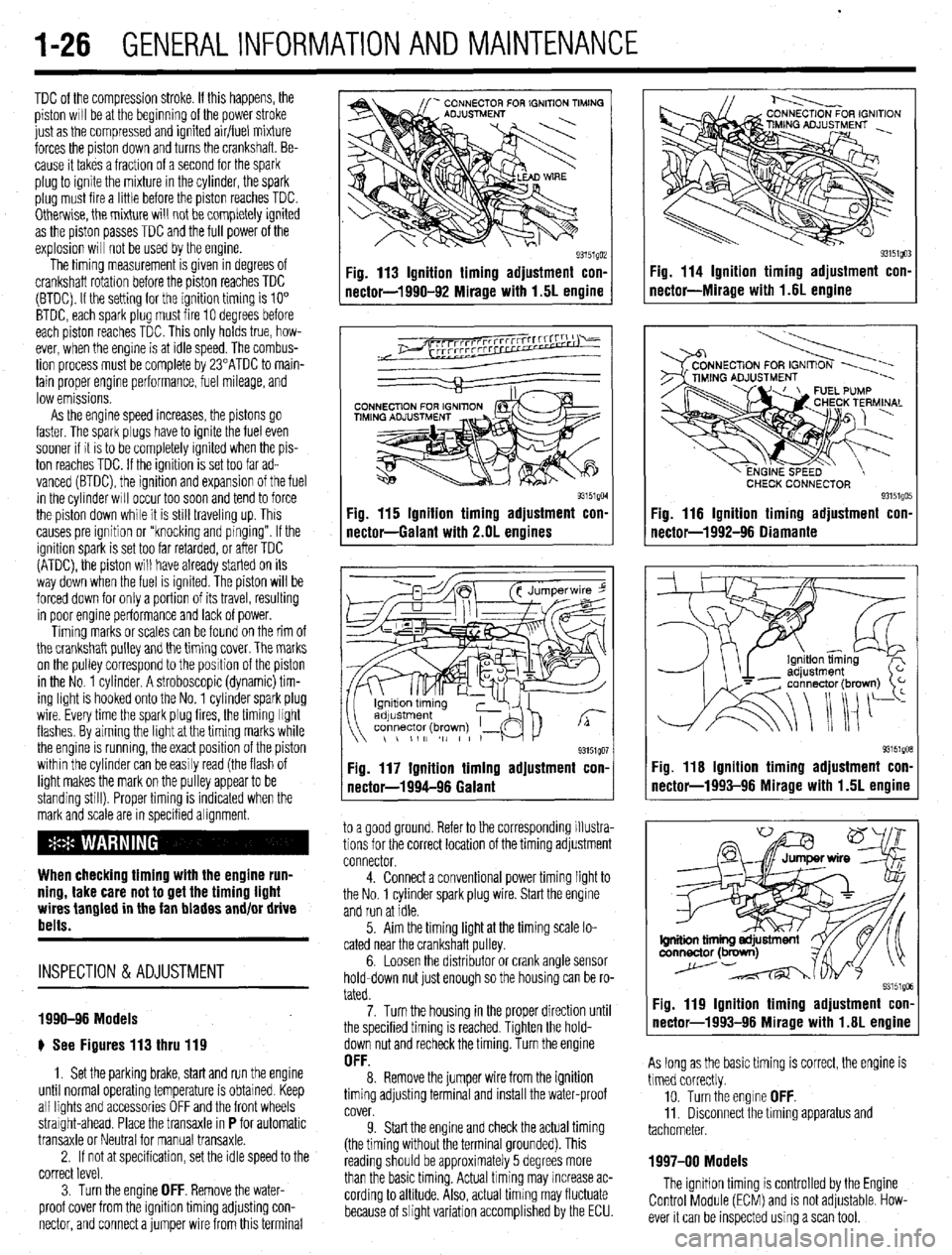
e See Figures 113 thru 119
1. Set the parking brake, start and run the engine
until normal operating temperature is obtained. Keep
all lights and accessories OFF and the front wheels
straight-ahead. Place the transaxle in
P for automatic
transaxle or Neutral for manual transaxle.
2. If not at specification, set the idle speed to the
correct level.
3. Turn the engine
OFF. Remove the water-
proof cover from the igmtion timing adjusting con-
nector, and connect a jumper wire from this terminal
Fig. 113 Ignition timing adjustment con-
nector-1990-92 Mirage with 1.5L engine
93151QM Fig. 115 Ignition timing adjustment con-
nectar-Galant with 2.OL engines
93151QO1 Fig. 117 Ignition timing adjustment con.
nectar-1994-96 Galant
to a good ground. Refer to the corresponding illustra-
tions for the correct location of the timing adjustment
connector.
4. Connect a conventional power timing light to
the No. 1 cylinder spark plug wire. Start the engine
and run at idle.
5. Aim the timing light at the timing scale lo-
cated near the crankshaft pulley.
6. Loosen the distributor or crank angle sensor
hold-down nut just enough so the housing can be ro-
tated.
7. Turn the housing in the proper direction until
the specified timing is reached. Tighten the hold-
down nut and recheck the timing. Turn the engine
OFF. 8. Remove the jumper wire from the ignition
timing adjusting terminal and install the water-proof
cover.
9. Start the engine and check the actual timing
(the timing without the terminal grounded). This
reading should be approximately 5 degrees more
than the basic timing. Actual timing may increase ac-
cording to altitude. Also, actual timing may fluctuate
because of slight variation accomplished by the ECU.
Fig. 114 Ignition timing adjustment con-
nectar-Miracle with 1.6L enaine
CHECK CONNECTOR 93151QO! Fig. 116 Ignition timing adjustment con.
nectar-1992-96 Oiamante
93151gOB Fig. 116 Ignition timing adjustment con-
nector-1993-96 Mirage with 1.5L engine
Fig. 119 Ignition timing adjustment con-
nector-1993-96 Mirage with 1.6L engine
As long as the basic timing is correct, the engine is
timed correctly.
10. Turn the engine
OFF. 11. Disconnect the timing apparatus and
tachometer.
1997-00 Models
The ignition timing is controlled by the Engine
Control Module (ECM) and is not adjustable. How-
ever it can be inspected using a scan tool.
Page 45 of 408
.
I-46 GENERALINFORMATIONAND MAINTENANCE
2. Pull the jumping vehicle (with the good bat-
tery) into a position so the jumper cables can reach
the dead battery and that vehicle’s engine. Make sure
that the vehicles do NOT touch.
3. Place the transmissions/transaxles of both ve-
hicles in Neutral (MT) or P (AT), as applicable, then
firmly set their parking brakes.
*ff necessary for safety reasons, the hazard
lights on both vehicles may be operated
throughout the entire procedure without sig-
nificantiy increasing the diff icuity of jumping
the dead battery.
4. Turn all lights and accessories OFF on both
vehicles. Make sure the ignition switches on both ve-
hicles are turned to the OFF position.
5. Cover the battery cell caps with a rag, but do
not cover the terminals.
6. Make sure the terminals on both batteries are
clean and free of corrosion or proper electrical con-
nection will be impeded. If necessary, clean the bat-
tery terminals before proceeding.
7. Identify the positive (+) and negative (-) termi-
nals on both batteries.
8. Connect the first jumper cable to the positive
(t) terminal of the dead battery, then connect the
other end of that cable to the positive (t) terminal of
the booster (good) battery.
9. Connect one end of the other jumper cable to
the negative (−) terminal on the booster bat-
tery and the final cable clamp to an engine bolt head,
alternator bracket or other solid, metallic point on the
engine with the dead battery. Try to pick a ground on
the engine that is positioned away from the battery in
order to minimize the possibility of the 2 clamps
touching should one loosen during the procedure.
DO NOT connect this clamp to the negative (-) termi-
nal of the bad battery. cable on the donor battery. Disconnect the positive
cable from the donor battery and finally, disconnect
the positive cable from the formerly dead battery. Be
careful when disconnecting the cables from the posi-
tive terminals not to allow the alligator clips to touch
any metal on either vehicle or a short and sparks will
occur.
I
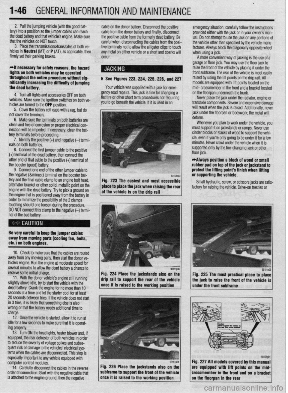
$ See Figures 223,224, 225,226, and 227
Your vehicle was supplied with a jack for emer-
gency road repairs. This jack is fine for changing a
flat tire or other short term procedures not requiring
you to go beneath the vehicle. If it is used in an emergency situation, carefully follow the instructions
provided either with the jack or in your owners man-
ual. Do not attempt to use the jack on any portions of
the vehicle other than specified by the vehicle manu-
facturer. Always block the diagonally opposite wheel
when using a jack.
A more convenient way of jacking is the use of a
garage or floor jack. You may use the floor jack to
raise the front of the vehicle by placing it under the
front subframe. The rear of the vehicle is most easily
raised by using the lift points on the drip rail. All
models are equipped with lift points located on the
mid- crossmember in the front and a bracket located
on the floorpan underneath the trunk.
Never place the jack under the radiator, engine or
transaxle components. Severe and expensive damage
will result when the jack is raised. Additionally, never
jack under the floorpan or
bodywork; the
metal will
Whenever you plan to work under the vehicle, you
must support it on jackstands or ramps. Never use
cinder blocks or stacks of wood to support the vehi-
cle, even if you’re only going to be under it for a few
minutes. Never crawl under the vehicle when it is
supported only by the tire-changing jack or other
*Always position a block of wood or small
rubber pad on top of the jack or jackstand to
protect the lifting point’s finish when lifting
or supporting the vehicle.
Small hydraulic, screw, or scissors jacks are satis-
factory for raising the vehicle. Drive-on trestles or
Be very careful to keep the jumper cables
away from moving parts (cooling fan, belts,
etc.) on both engines.
10. Check to make sure that the cables are routed
away from any moving parts, then start the donor ve-
hicle’s engine. Run the engine at moderate speed for
several minutes to allow the dead battery a chance to
receive some initial charge.
11. With the donor vehicle’s engine still running
slightly above idle, try to start the vehicle with the
dead battery. Crank the engine for no more than 10 &stands also on the
Fig. 225 The most practical place to place
front of the vehicle is
seconds at a time and let the starter cool for at least
20 seconds between tries. If the vehicle does not start
in 3 tries, it is likely thatsomething else is also
wrong or that the battery needs additional time to
charge.
12. Once the vehicle is started, allow it to run at
idle for a few seconds to make sure that it is operat-
ing properly.
13. Turn ON the headlights, heater blower and, if
equipped, the rear defroster of both vehicles in order
to reduce the severity of voltage spikes and subse-
quent risk of damage to the vehicles’ electrical sys-
tems when the cables are disconnected. This step is
especially important to any vehicle equipped with
computer control modules.
14. Carefully disconnect the cables in the’reverse
order of connection. Start with the negative cable that
is attached to the engine ground, then the negative Fig. 226 Place the jackstands also
subframe to support the front of the Fig. 227 All models covered by this
are equipped with lift points on t
crossmember in the front and on a
Page 56 of 408
ENGlNEELECTRldAL 2-9
TESTING
Voltage Test able for use by customers. An alternator
bench test is the most definitive way to de-
termine the condition of your alternator.
REMOVAL&INSTALLATION
1. Make sure the engine is OFF, and turn the 1.51,1.61, 1.6L, 2.OL and 2.4L Engines
headlights on for 15-20 seconds to remove any sur-
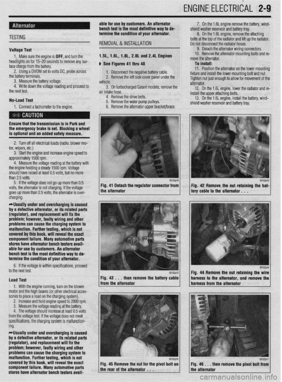
face charge from the battery. , See Figures 4, thru 48
2. Using a DVOM set to volts DC, probe across
1. Disconnect the negative battery cable.
the battery terminals.
3. Measure the battery voltage. 2. Remove the left side cover panel under the
vehicle.
4. Write down the voltage reading and proceed to
3. On turbocharaed Galant models, remove the
the next test.
air intake hose. -
No-load Test
1. Connect a tachometer to the engine. 4. Remove the drive belts.
5. Remove the water pump pulleys.
6. Remove the alternator upper bracket/brace.
Ensure that the transmission
is in Park and the emergency brake is set. Blocking a wheel
is optional and an added safety measure.
2. Turn off all electrical loads (radio, blower mo-
tor, wipers, etc.)
3. Start the engine and increase engine speed to
approximately 1500 rpm.
4. Measure the voltage reading at the battery with
the engine holding a steady 1500 rpm. Voltage
should have raised at least 0.5 volts, but no more
than 2.5 volts.
5. If the voltage does not go up more than 0.5
volts, the alternator is not charging. If the voltage
goes up more than 2.5 volts, the alternator is over-
* 7. On the 1.6L engine remove the battery, wind-
shield washer reservoir and battery tray.
8. On the 1.6L engine, remove the attaching
bolts at the top of the radiator and lift up the radiator.
Do not disconnect the radiator hoses.
9. Detach the alternator wiring connectors.
10. Remove the alternator mounting bolts and re-
move the alternator.
To install:
11. Position the alternator on the lower mountina
fixture and install the lower mounting bolt and nut. U
Tighten nut just enough to allow for movement of the
alternator.
12. On the 1.6L engine, lower the radiator and re-
install the upper attaching bolts.
13. On the 1.6L engine, install the battery, wind-
shield washer reservoir and battery tray.
/ tery cable to the alternator . , . 93152p12 Fig 42 Remove the nut retaining the bat-
cnargmg.
*Usually under and overcharging is‘caused
by a defective alternator, or its related parts
(regulator), and replacement will fix the
problem; however, faulty wiring and other
problems can
cause the charging system to
malfunction. Further testing, which is not
covered by this book, will reveal the exact
component failure. Many automotive parts
stores have alternator bench testers avaii-
able for use by customers. An alternator
bench test is the most definitive way to de-
termine the condition of your alternator.
6. If the voltage is within specifications, proceeU
to the next test.
Load Test
1. With the engine running, turn on the blower
motor and the hioh beams (or other electrical acces-
sories to place aioad on the charging system). Fig. 44 Remove the nut retaining the
then remove the batte harness to the alternator and remov
,
2. Increase and hold engine speed to 2000 rpm.
3. Measure the voltage reading at the battery.
4. The voltage should increase at least 0.5 volts
from the voltage test. If the voltage does not meet
specifications, the charging system is malfunction-
ing.
*Usually under and overcharging is caused
by a defective alternator, or its related parts
(regulator), and replacement will fix the
problem; however, faulty wiring and other
problems can cause the charging system to
malfunction. Further testing, which is not
covered by this book, will reveal the exact
component failure. Many automotive parts
stores have alternator bench testers avaii-
93152p17 en remove the pivot bolt from
Page 59 of 408
.
2-12 ENGINEELECTRICAL
*This section describes the operating prina
ciples of sending units, warning lights and
gauges. Sensors which provide information
to the Enafne Control Unit (ECU) or Electronic
or Power&in Control Module (FCM/PCM) are
covered in Section 4 of this manual.
Instrument panels contain a number of indicating
devices (gauges and warning lights). These devices
are composed of two separate components. One is
the sending unit, mounted on the engine or other re-
mote part of the vehicle, and the other is the actual
gauge or light in the instrument panel.
Several types of sending units exist, however most
can be characterized as being either a pressure type
or a resistance type. Pressure type sending units
convert liquid pressure into an electrical signal which
is sent to the gauge. Resistance type sending units
are most often used to measure temperature and use
variable resistance to control the current flow back to
the indicatinq device. Both types of sendinq units are
connected inseries by a wimto the batteryithiough
the ignition switch). When the ignition is turned ON,
current flows from the battery through the indicating
device and on to the sending unit.
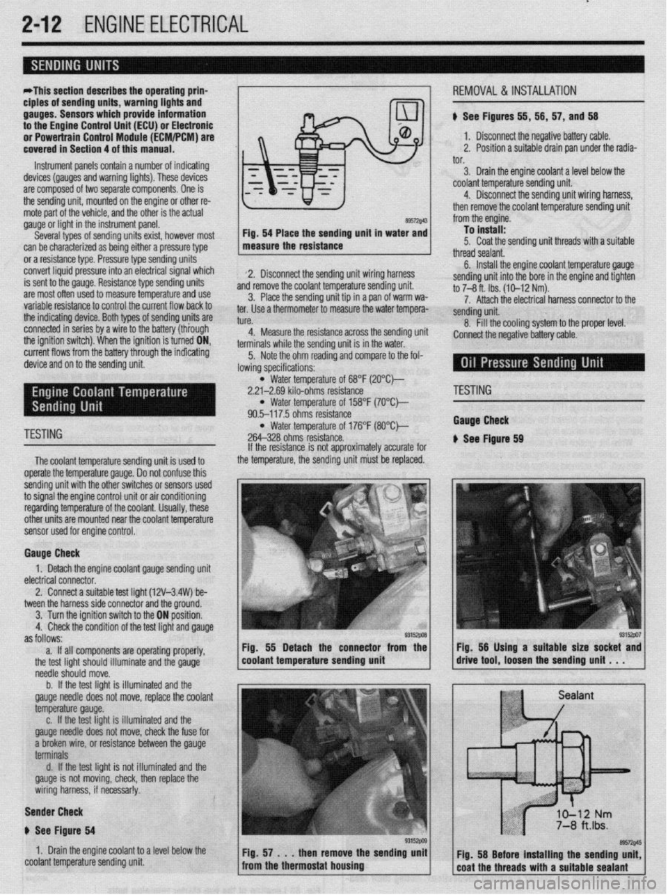
89572$43 Fig. 54 Place the sending unit in water and
measure the resistance
2. Disconnect the sending unit wiring harness
and remove the coolant temperature sending unit.
3. Place the sending unit tip in a pan of warm wa-
ter. Use a thermometer to measure the water tempera-
tl KP
L”,“.
4. Measure the resistance across the sending uni
terminals while the sending unit is in the water.
5. Note the ohm reading and compare to the fol-
lowing specifications: i, 56, 57, and 56
1. Disconnect the negative battery cable.
2. Position a suitable drain pan under the radia-
tor.
3. Drain the engine coolant a level below the
coolant temperature sending unit.
4. Disconnect the sending unit wiring harness,
then remove the coolant temperature sending unit
from the engine.
To install:
5. Coat the sending unit threads with a suitable
thread sealant.
6. Install the engine coolant temperature gauge
sending unit into the bore in the engine and tighten
to 7-8 ft. Ibs. (10-12 Nm).
7. Attach the electrical harness connector to the
sendina unit.
8. fill the cooling system to the proper level.
:onnect the negative battery cable.
l Water temperature of 68°F (2O”C)-
2.21-2.69 kilo-ohms resistance
l Water temperature of 158°F (7O’Ck
90.5-117.5 ohms resistance
TESTING l Water temperature of 176°F (8O”C)-
264-328 ohms resistance.
The coolant temperature sendina unit is used to
operate the temperature gauge. Donot confuse this
sending unit with the other switches or sensors used
to signal the engine control unit or air conditioning
regarding temperature of the coolant. Usually, these
other units are mounted near the coolant temoerature
sensor used for engine control. If the resistance is not approximately accurate for
the temperature, the sending unit must be replaced.
Gauge Check
1. Detach the engine coolant gauge sending unit
electrical connector.
2. Connect a suitable test liaht (12V-3.4W) be-
tween the harness side connector and the around.
I
3. Turn the ignition switch to the ON position.
4. Check the condition of the test light and gauge
as follows:
a. If all components are operating properly,
the test light should illuminate and the gauge
needle should move.
b. If the test light is illuminated and the
gauge needle does not move, replace the coolant
temperature gauge.
c. If the test light is illuminated and the
gauge needle does not move, check the fuse for
a broken wire, or resistance between the gauge
terminals
d. If the test light is not illuminated and the
gauge is not moving, check, then replace the
wiring harness, if necessar!y.
Sender Check
p See Figure 64
1. Drain the engine coolant to a level below the
coolant temperature sending unit Fig. 55 Detach the connector from the
coolant temperature sending unit
'ESTING
tauga Check
See Ftgure 69
Page 60 of 408
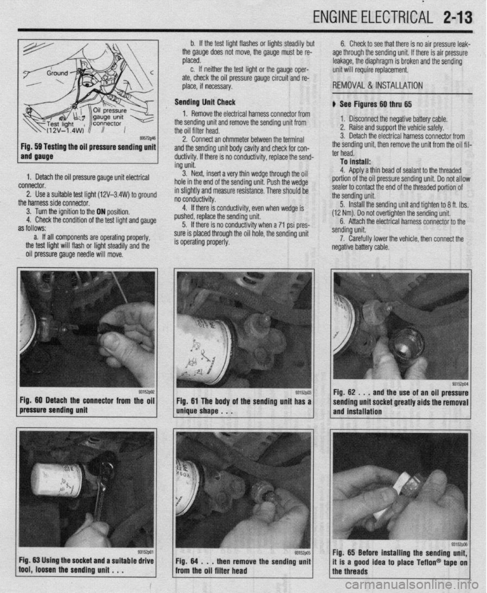
ENGINE ELECTRlCiL 2-13
ing the oil pressure sending unit
1. Detach the oil pressure gauge unit electrical
connector.
2. Use a suitable test lioht (12V-3.4W) to around
the harnesssideconnecto~ ’ ’ -
3. Turn the ignition to the ON position.
4. Check the condition of the test light and gauge
as follows:
a. If all components are operating properly,
the test light will flash or light steadily and the
oil pressure gauge needle will move. b. If the test light flashes or lights steadily but
the gauge does not move, the gauge must be re-
placed.
c. If neither the test light or the gauge oper-
ate, check the oil pressure gauge circuit and re-
place, if necessary.
Sending Unit Check
1. Remove the electrical harness connector from
the sending unit and remove the sending unit from
the oil filter head.
2. Connect an ohmmeter between the terminal
and the sending unit body cavity and check for con-
ductivity. If there is no conductivity, replace the send-
ing unit.
3. Next, insert a very thin wedge through the oil
hole in the end of the sending unit. Push the wedge
in slightly and measure resistance. There should be
- - -- d . . . .
no conoucovey.
4. If there is conductivity, even when wedge is
pushed, replace the sending unit.
5. If there is no conductivity when a 71 psi pres-
sure is placed through the oil hole, the sending unit
is operating properly. 6. Check to see that there is no air pressure leak-
age through the sending unit. If there is air pressure
leakage, the diaphragm is broken and the sending
unit will require replacement.
REMOVAL &INSTALLATION
b See Figures 60 thru 65
1. Disconnect the negative battery cable.
2. Raise and support the vehicle safely.
3. Detach the electrical harness connector from
the sending unit, then remove the unit from the oil fil-
ter head.
To install:
4. Aoolv a thin bead of sealant to the threaded
portion of the oil pressure sending unit. Do not allow
sealer to contact the end of the threaded portion of
the sending unit.
5. Install the sending unit and tighten to 8 ft. tbs.
(12 Nm). Do not over-tighten the sending unit.
6. Attach the electrical harness connector to the
/pressure sending unit g3’9wi / m&e shape . . . Fig 60 Detach the connector from the oil
g3152w Fig 61 The body of the sending unit has a sending unit.
7. Carefully lower the vehicle, then connect the
negative battery cable.
93152PM Fig. 62 . , .
and the use of an oil pressure
sending unit socket greatly aids the removal
and installation
Fig. 65 Before installing the sending unit,
it is a good idea to place Teflon@ tape on
the threads
Page 87 of 408
3-26 ENGINEANDENGINEOVERHAUL
18. Remove the self-locking nuts and the small
retaining bolt holding the exhaust pipe to the bottom
of the exhaust manifold. Separate the pipe from the
manifold and remove the gasket.
19. Remove the bolts holding the support brace
to the bottom of the intake manifold.
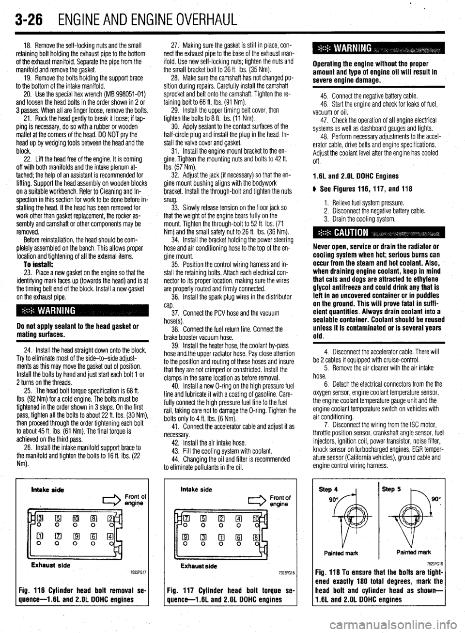
20. Use the special hex wrench (MB 998051-01)
and loosen the head bolts in the order shown in 2 or
3 passes. When all are finger loose, remove the bolts.
21. Rock the head gently to break it loose; if tap-
ping is necessary, do so with a rubber or wooden
mallet at the corners of the head. DO NOT pry the
head up by wedging tools between the head and the
block.
22. Lift the head free of the engine. It is coming
off with both manifolds and the intake plenum at-
tached; the help of an assistant is recommended for
lifting. Support the head assembly on wooden blocks
on a suitable workbench. Refer to Cleaning and In-
spection in this section for work to be done before in-
stalling the head. If the head has been removed for
work other than gasket replacement, the rocker as-
sembly and camshaft or other components may be
removed.
Before reinstallation, the head should be com-
pletely assembled on the bench. This allows proper
location and tightening of all the external items.
To install: 23. Place a new gasket on the engine so that the
identifying mark faces up (towards the head) and is at
the timing belt end of the block. Install a new gasket
on the exhaust pipe.
Do not apply sealant to the head gasket or
mating surfaces.
24. Install the head straight down onto the block.
Try to eliminate most of the side-to-side adjust-
ments as this may move the gasket out of position.
Install the bolts by hand and just start each bolt 1 or
2 turns on the threads.
25. The head bolt torque specification is 68 ft.
Ibs. (92 Nm) for a cold engine. The bolts must be
tightened in the order shown in 3 steps. On the first
pass, tighten all the bolts to about 22 ft. Ibs. (30 Nm),
then proceed through the order tightening each bolt
to about 45 ft. Ibs. (61 Nm). The final torque is
achieved on the third pass.
26. Install the intake manifold support brace to
the manifold and tighten the bolts to 16 ft. Ibs. (22
Nm). 27. Making sure the gasket is still in place, con-
nect the exhaust pipe to the base of the exhaust man-
ifold. Use new self-locking nuts; tighten the nuts and
the small bracket bolt to 26 ft. Ibs. (35 Nm).
28. Make sure the camshaft has not changed po-
sition during repalrs. Carefully install the camshaft
sprocket and belt onto the camshaft. Tighten the re-
taining bolt to 66 ft. Ibs. (91 Nm).
29. Install the upper timing belt cover, then
tighten the bolts to 8 ft. Ibs. (11 Nm).
30. Apply sealant to the contact surfaces of the
half-circle plug and install the plug in the head In-
stall the valve cover and gasket.
31. Install the engine mount bracket to the en-
gine. Tighten the mounting nuts and bolts to 42 ft.
Ibs. (57 Nm).
32. Adjust the jack (if necessary) so that the en-
gine mount bushing aligns with the bodywork
bracket. Install the through-bolt and tighten the nuts
snug.
33. Slowly release tension on the floor jack so
that the weight of the engine bears fully on the
mount. Tighten the through-bolt to 52 ft. Ibs. (71
Nm) and the small safety nut to 26 ft. tbs. (36 Nm).
34. Install the bracket holding the power steering
hose and air conditioning hose to the top of the en-
gine mount.
35. Position the control wiring harness and in-
stall the retaining bolts. Attach each electrical con-
nector to its proper location, making sure the wires
are properly routed and firmly connected.
36. Install the spark plug wires in the distributor
cap.
37. Connect the PCV hose and the vacuum
hose(s).
38. Connect the fuel return line. Connect the
brake booster vacuum hose.
39. Install the heater hose, the coolant by-pass
hose and.the upper radiator hose. Pay close attention
to the position and routing of these hoses and insure
that they are not crimped or constricted. Install the
clamps in the same location as before removal.
40. Install a new O-ring on the high pressure fuel
line and lubricate it with a coating of gasoline. Care-
fully connect the high pressure fuel line to the fuel
rail, taking care not to damage the O-ring. Tighten the
bolts only to 4 ft. Ibs. (6 Nm).
41. Connect the accelerator cable and adjust it as
necessary.
42. Install the air intake hose.
43. Fill the cooling system with coolant.
44. Changing the oil and filter is recommended
to eliminate pollutants in the oil.
Intake side
I Front of
engine
Exhaust side
Fig. 116 Cylinder head bolt removal se-
quence-l .6L and 2.OL DDHC engines intake
side
Front of
entine
Exhaust side 7923PG18
Fig. 117 Cylinder head bolt torque se-
quence-l .6L and 2.OL DDHC engines Operating the engine without the proper
amount and type of engine oil will result in
severe engine damage.
45. Connect the negative battery cable.
46. Start the engine and check for leaks of fuel,
vacuum or oil.
47. Check the operation of all engine electrical
systems as well as dashboard gauges and lights.
48. Perform necessary adjustments to the accel-
erator cable, drive belts and engine specifications.
Adjust the coolant level after the engine has cooled
Off.
1.6L and 2.OL DDHC Engines
ti See Figures 116,117, and 116
1. Relieve fuel system pressure.
2. Disconnect the negative battery cable.
3. Drain the cooling system.
Never open, service or drain the radiator or
cooling system when hot; serious burns can
occur from the steam and hot coolant. Also,
when draining engine coolant, keep in mind
that cats and dogs are attracted to ethylene
glycol antifreeze and could drink any that is
left in an uncovered container or in puddles
on the ground. This will prove fatal in suffi-
cient quantities. Always drain coolant into a
sealable container. Coolant should be reused
unless it is contaminated or is several years
old.
4. Disconnect the accelerator cable. There will
be 2 cables if equipped with cruise-control.
5. Remove the air cleaner with the air intake
hose.
6. Detach the electrical connectors from the the
oxygen sensor, engine coolant temperature sensor,
the engine coolant temperature gauge unit and the
engine coolant temperature switch on vehicles with
air conditioning.
7. Disconnect the wiring from the ISC motor,
throttle position sensor, crankshaft angle sensor, fuel
injectors, ignition coil, power transistor, noise filter,
knock sensor on turbocharged engines, EGR temper-
ature sensor (California vehicles), ground cable and
engine control wiring harness.
Painted mark Painted mark
Fig. 116 To ensure that the bolts are tight-
ened exactly 160 total degrees, mark the
11.6L and 2.OL DDHC engines head bolt and cylinder head as shown-
Page 204 of 408

UNDERSTANDING AND
TROUBLESHOOTING
ELECTRICAL SYSTEMS 6-2
BASIC ELECTRICALTHEORY 6-2
HOW DOES ELECTRICITY WORK:
THEWATERANALOGY 6-2
OHM'S LAW 6-2
ELECTRICALCOMPONENTS 6-2
POWERSOURCE 6-2
GROUND 6-3
PROTECTIVE DEVICES 6-3
SWITCHES&RELAYS 6-3
LOAD 6-3
WIRING & HARNESSES 6-3
CONNECTORS 6-4
TEST EQUIPMENT 6-4
JUMPER WIRES 6-4
TEST LIGHTS 6-4
MULTIMETERS 6-5
TROUBLESHOOTING ELECTRICAL
SYSTEMS 6-5
TESTING 6-5
OPEN CIRCUITS 6-5
SHORT CIRCUITS 6-6
VOLTAGE 6-6
VOLTAGE DROP 6-6
RESISTANCE 6-8
WIRE AND CONNECTORREPAIR 6-6
BATTERY CABLES 6-7
DISCONNECTING THE CABLES 6-7
AIR BAG (SUPPLEMENTAL
RESTRAINT SYSTEM) 6-7
GENERALINFORMATION 6-7
SERVICE PRECAUTIONS 6-7
DISARMING 6-7
REARMING 6-7
HEATING AND AIR
CONDITIONING 6-7
BLOWER MOTOR 6-7
REMOVAL &INSTALLATION 6-7
HEATER CORE 6-9 INSTRUMENTS AND SWITCHES 6-17
INSTRUMENTCLUSTER 6-17
REMOVAL &INSTALLATION 6-17
GAUGES 6-18
REMOVAL&INSTALLATION 6-18
WINDSHIELD WIPER SWITCH 6-19
REMOVAL&INSTALLATION 6-19
REARWINDOWWIPERSWITCH 6-19
REMOVAL &INSTALLATION 6-19
DIMMER SWITCH 6-19
REMOVAL & INSTALLATION 6-19 .
HEADLIGHT SWITCH 6-19
REMOVAL & INSTALLATION 6-19
LIGHTING 6-19
HEADLIGHTS 6-19
REMOVAL &INSTALLATION 6-19
AIMINGTHEHEADLIGHTS 6-20
SIGNAL AND MARKER LIGHTS 6-21
REMOVAL &INSTALLATION 6-21
CIRCUIT PROTECTION 6-27
FUSES 6-27
REPLACEMENT 6-27
FUSIBLE LINKS 6-27
CIRCUIT BREAKERS 6-28
RESETTING AND/OR
REPLACEMENT 6-28
FLASHERS 6-28
REPLACEMENT 6-28
WIRING DIAGRAMS 6-31
REMOVAL & INSTALLATION 6-9
AIR CONDITIONING COMPONENTS 6-11
REMOVAL & INSTALLATION 6-11
CONTROLCABLES 6-12
ADJUSTMENT 6-12
CONTROL PANEL 6-12
REMOVAL & INSTALLATION 6-12
CRUISE CONTROL 6-13
ENTERTAINMENT SYSTEMS 6-14
RADIO RECEIVER/AMPLIFIER/TAPE
PLAYER/CD PLAYER 6-14
SPEAKERS 6-14
REMOVAL & INSTALLATION 6-14
WINDSHIELD WIPERS AND
WASHERS 6-15
WINDSHIELD WIPER BLADE AND
ARM 6-15
REMOVAL & INSTALLATION 6-15
WINDSHIELD WIPER MOTOR 6-16 _
REMOVAL &INSTALLATION 6-16
WINDSHIELD WASHER PUMP 6-17
REMOVAL &INSTALLATION 6-17
Page 207 of 408
I
6-4 CHASSIS ELECTRICAL
I
printed circuit is sandwiched between two sheets of
plastic for more protection and flexibility. A complete l Weatherproof-these connectors are most the jumper wire is of too small a gauge, it
printed circuit, consisting of conductors, insulating commonly used where the connector is exposed to
may overheat and possibly melt. Never use
material and connectors for lamps or other compo- the elements. Terminals are protected against mois-
nents is called a printed circuit board. Printed cir- ture and dirt by sealing rings which provide a weath- jumpers to bypass high resistance loads in a
et-tight seal. All repairs require the use of a special circuit. Bypassing resistances, in effect, cre-
cuitry is used in place of individual wires or har- ates a short circuit. This may, in turn, cause
nesses in places where space is limited, such as terminal and the tool required to service it. Unlike
behind instrument panels. standard blade type terminals, these weatherproof damage and fire. Jumper wires should only
be used to bypass lengths of wire or to simu-
Since automotive electrical systems are very sen- terminals cannot be straightened once they are bent. late switches.
sitive to changes in resistance, the selection of prop- ‘Make certain that the connectors are properly seated
erly sized wires is critical when systems are repaired, and all of the sealing rings are in place when con-
netting leads. Jumper wires are simple, yet extremely valuable,
A loose or corroded connection or a replacement wire pieces of test equipment. They are basically test wires
that is too small for the circuit will add extra resis-
l Molded-these connectors require complete which are used to bypass sections of a circuit. Al-
replacement of the connector if found to be defective.
tance and an additional voltage drop to the circuit. though jumper wires can be purchased, they are usu-
The wire gauge number is an expression of the This means splicing a new connector assembly into ally fabricated from lengths of standard automotive
cross-section area of the conductor. Vehicles from the harness. All splices should be soldered to insure
proper contact. Use care when probing the connec- wire and whatever type of connector (alligator clip,
countries that use the metric system will typically de- spade connector or pin connector) that is required for
scribe the wire size as its cross-sectional area in tions or replacing terminals in them, as it is possible
square millimeters. In this method, the larger the to create a short circuit between opposite terminals. If the particular application being tested. In cramped,
hard-to-reach areas, it is advisable to have insulated
wire, the greater the number. Another common sys- this happens to the wrong terminal pair, it is possible
to damage certain components. Always use jumper boots over the jumper wire terminals in order to pre-
tern for expressing wire size is the American Wire vent accidental grounding. It is also advisable to in-
Gauge (AWG) system. As gauge number increases, wires between connectors for circuit checking and
NEVER probe through weatherproof seals. elude a standard automotive fuse in any jumper wire.
area decreases and the wire becomes smaller. An 18
gauge wire is smaller than a 4 gauge wire. A wire
l Hard Shell-unlike molded connectors, the This is commonly referred to as a “fused jumper”. By
inserting an in-line fuse holder between a set of test
terminal contacts in hard-shell connectors can be re-
with a higher gauge number will carry less current
placed. Replacement usually involves the use of a leads, a fused jumper wire can be used for bypassing :
than a wire with a lower gauge number. Gauge wire open circuits. Use a 5 amp fuse to provide protection
size refers to the size of the strands of the conductor, special terminal removal tool that depresses the lock- against voltage spikes.
not the size of the complete wire with insulator. It is ing tangs (barbs) on the connector terminal and al-
lows the connector to be removed from the rear of the Jumper wires are used primarily to locate open
possible, therefore, to have two wires of the same
shell. The connector shell should be replaced if it electrical circuits, on either the ground (-) side of the
gauge with different diameters because one may have
thicker insulation than the other. shows any evidence of burning, melting, cracks, or circuit or on the power (+) side. If an electrical corn-
breaks. Replace individual terminals that are burnt, ponent fails to operate, connect the jumper wire be-
It is essential to understand how a circuit works
corroded, distorted or loose. tween the component and a good ground. If the corn-
before trying to figure out why it doesn’t. An electrical ponent operates only with the jumper installed, the
schematic shows the electrical current paths when a ground circuit is open. If the ground circuit is good,
circuit is operating properly. Schematics break the but the component does not operate, the circuit be-
entire electrical system down into individual circuits. tween the power feed and component may be open. ’
In a schematic, usually no attempt is made to repre- Pinpointing the exact cause of trouble in an elec- By moving the jumper wire successively back from
trical circuit is most times accomplished by the use the component toward the power source, you can
; : sent wiring and components as they physically ap-
pear on the vehicle; switches and other components of special test equipment. The following describes isolate the area of the circuit where the open is lo-
are shown as simply as possible. Face views of har- different types of commonly used test equipment and cated. When the component stops functioning, or the f
j
ness connectors show the cavity or terminal locations briefly explains how to use them in diagnosis. In ad- power is cut off, the open is in the segment of wire j
in all multi-pin connectors to help locate test points. dition to the information covered below, the tool between the jumper and the point previously tested.
! manufacturer’s instructions booklet (provided with You can sometimes connect the jumper wire di-
the tester) should be read and clearly under.$ood be- rectly from the battery to the “hot” terminal of the I
CONNECTORS 1 fore attempting any test procedures. component, but first make sure the component uses 1
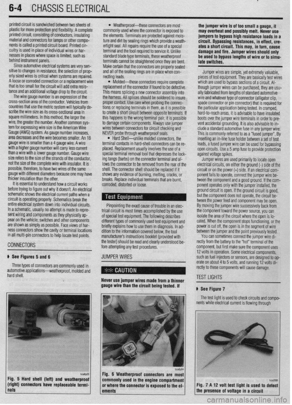
# See Figures 5 and 6 JUMPER WIRES 12 volts in operation. Some electrical components, i
such as fuel injectors or sensors, are designed to op-
Three types of connectors are commonly used in erate on about 4 to 5 volts, and running 12 volts di- j
)
automotive applications-weatherproof, molded and rectly to these components will cause damage.
hard shell.
Never use jumper wires made from a thinner TEST LIGHTS I
gauge wire than the circuit being tested. If
# See Figure 7
The test light is used to check circuits and compo-
I nents while electrical current is flowing through
Fig. 5 Hard shell (left) and weatherproof
(right) connectors have replaceable termi- Fig. 7 A 12 volt test light is used to di%
nals
ements 1 the presence of voltage in a circuit
Page 208 of 408
CHASSIS ELECTRiCAL 6-5
them. It is used for voltage and ground tests. To use voltmeter has a positive and a negative lead. To avoid
a 12 volt test light, connect the ground clip to a good damage to the meter, always connect the negative
ground and probe wherever necessary with the pick. lead to the negative (-) side of the circuit (to ground
The test light will illuminate when voltage is detected. or nearest the ground side of the circuit) and connect
This
does not necessarily mean that 12 volts (or any the positive lead to the positive(t) side of the circuit When diagnosing a specific problem, organized
troubleshooting is a must. The complexity of a mod-
particular amount of voltage) is present; it only (to the power source or the nearest power source).
means that some voltage is present. It is advisable Note that the negative voltmeter lead will always be ern automotive vehicle demands that you approach
before using the test light to touch its ground clip black and that the positive voltmeter will always be any problem in a logical, organized manner. There
and probe across the battery posts or terminals to some color other than black (usually red). are certain troubleshooting techniques, however,
which are standard:
make sure the light is operating properly.
l Ohmmeter-the ohmmeter is designed to read l Establish when the problem occurs. Does the
resistance (measured in ohms) in a circuit or compo-
nent. Most ohmmeters will have a selector switch problem appear only under certain conditions? Were
there any noises, odors or other unusual symptoms?
Do not use a test light to probe electronic ig- which permits the measurement of different ranges of
Isolate the problem area. To do this, make some sim-
nition, spark plug or coil wires. Never use a resistance (usually the selector switch allows the
multiplication of the meter reading by 10,100,1,000 ple tests and observations, then eliminate the sys-
pick-type test light to probe wiring on com- terns that are working properly. Check for obvious
puter controlled systems unless specifically and 10,000). Some ohmmeters are “auto-ranging”
which means the meter itself will determine which problems, such as broken wires and loose or dirty
instructed to do so. Any wire insulation that
scale to use. Since the meters are powered by an in- connections. Always check the obvious before as-
is pierced by the test light probe should be
ternal battery, the ohmmeter can be used like a self- suming something complicated is the cause.
taped and sealed with silicone after testing.
l Test for problems systematically to determine
powered test light. When the ohmmeter is connected,
the cause once the problem area is isolated. Are all
Like the jumper wire, the 12 volt test light is used current from the ohmmeter flows through the circuit
the components functioning properly? Is there power
to isolate opens in circuits. But, whereas the jumper or component being tested. Since the ohmmeter’s in-
ternal resistance and voltage are known values, the going to electrical switches and motors. Performing
wire is used to bypass the open to operate the load,
amount of current flow through the meter depends on careful, systematic checks will often turn up most
the 12 volt test light is used to locate the presence of
the resistance of the circuit or component being causes on the first inspection, without wasting time
voltage in a circuit. If the test light illuminates, there
tested. The ohmmeter can also be used to perform a checking components that have little or no relation-
is power up to that point in the circuit; if the test light ship to the problem.
does not illuminate, there is an open circuit (no continuity test for suspected open circuits. In using
the meter for making continuity checks, do not be
l Test all repairs after the work is done to make
power). Move the test light in successive steps back
concerned with the
actual resistance readings. Zero sure that the problem is fixed. Some causes can be
toward the power source until the light in the handle traced to more than one component, so a careful veri-
illuminates. The open is between the probe and a resistance, or any ohm reading, indicates continuity
fication of repair work is important in order to pick up
point which was previously probed. in the circuit, Infinite resistance indicates an opening
in the circuit. A high resistance reading where there additional malfunctions that may cause a problem to
The self-powered test light is similar in design to
should be none indicates a problem in the circuit. reappear or a different problem to arise. A blown
the 12 volt test light, but contains a 1.5 volt penlight
Checks for short circuits are made in the same man- fuse, for example, is a simple problem that may re-
battery in the handle. It is most often used in place of
ner as checks for open circuits, except that the circuit quire more than another fuse to repair. If you don’t
a multimeter to check for open or short circuits when look for a problem that caused a fuse to blow, a
power is isolated from the circuit (continuity test). must be isolated from both power and normal
ground. Infinite resistance indicates no continuity, shorted wire (for example) may go undetected.
The battery in a self-powered test light does not Experience has shown that most problems tend
provide much current. A weak battery may not pro- while zero resistance indicates a dead short.
to be the result of a fairly simple and obvious
vide enough power to illuminate the test light even I ’ cause, such as loose or corroded connectors, bad
when a complete circuit is made (especially if there is grounds or damaged wire insulation which causes a
high resistance in the circuit). Always make sure that Never use an ohmmeter to check the resis- short. This makes careful visual inspection of com-
the test battery is strong. To check the battery, briefly tance of a component or wire while there is ponents during testing essential to quick and accu-
touch the ground clip to the probe; if the light glows voltage applied to the circuit. rate troubleshooting.
brightly, the battery is strong enough for testing.
*A self-powered test light should not be
l Ammeter-an ammeter measures the amount
- I
used on any computer controlled system or of current flowing through a circuit in units called
component. The small amount of electricity amperes or amps. At normal operating voltage, most
circuits have a characteristic amount of amperes, OPEN CIRCUITS
transmitted by the test light is enough to
damage many electronic automotive compo- called “current draw” which can be measured using
an ammeter. By referring to a specified current draw # See Figure 8
nents.
rating, then measuring the amperes and comparing
MULTIMETERS the two values, one can determine what is happening
within the circuit to aid in diagnosis. An open circuit,
for example, will not allow any current to flow, so the
Multimeters are an extremely useful tool for trou-
bleshooting electrical problems. They can be pur- ammeter reading will be zero. A damaged component
or circuit will have an increased current draw, so the
chased in either analog or digital form and have a
reading will be high. The ammeter is always con-
price range to suit any budget. A multimeter is a volt-
netted in series with the circuit being tested. All of
meter, ammeter and ohmmeter (along with other fea-
the current that normally flows through the circuit
tures) combined into one instrument. It is often used
must also flow through the ammeter; if there is any
when testing solid state circuits because of its high
other path for the current to follow, the ammeter read-
input impedance (usually 10 megaohms or more). A
ing will not be accurate. The ammeter itself has very
brief description of the multiieter main test functions
follows: little resistance to current flow and, therefore, will not
affect the circuit, but it will measure current draw only
l Voltmeter--the voltmeter is used to measure
when the circuit is closed and electricity is flowing.
voltage at any point in a circuit, or to measure the
Excessive current draw can blow fuses and drain the
voltage drop across any part of a circuit. Voltmeters
battery, while a reduced current draw can cause mo-
usually have various scales and a selector switch to
tors to run slowly, lights to dim and other compo-
allow the reading of different voltage ranges. The
nents to not operate properly.
Page 210 of 408
I I
CHASSIS ELECTRICAL 6-7
When working on any electrical component on the
vehicle, it is always a good idea to disconnect the
negative (-) battery cable. This will prevent potential
damage to many sensitive electrical components
such as the Powertrain Control Module (PCM), radio,
alternator, etc.
*Any time you disengage the battery cables,
it is recommended that you disconnect the negative (-) battery cable first. This will pre-
vent your accidentally grounding the positive
(+) terminal to the body of the vehicle when
disconnecting it, thereby preventing damage
to the above mentioned components.
Before you disconnect the cable(s), first turn the
ignition to the OFF position. This will prevent a draw
on the battery which could cause arcing (electricity
trying to ground itself to the body of a vehicle, just
like a spark plug jumping the gap) and, of course, damaging some components such as the alternator
diodes.
When the battery cable(s) are reconnected (nega-
tive cable last), be sure to check that your lights,
windshield wipers and other electrically operated
safety components are all working correctly. If your
vehicle contains an Electronically Tuned Radio (ETR),
don’t forget to also reset your radio stations. Ditto for
the clock.
SERVICE PRECAUTIONS
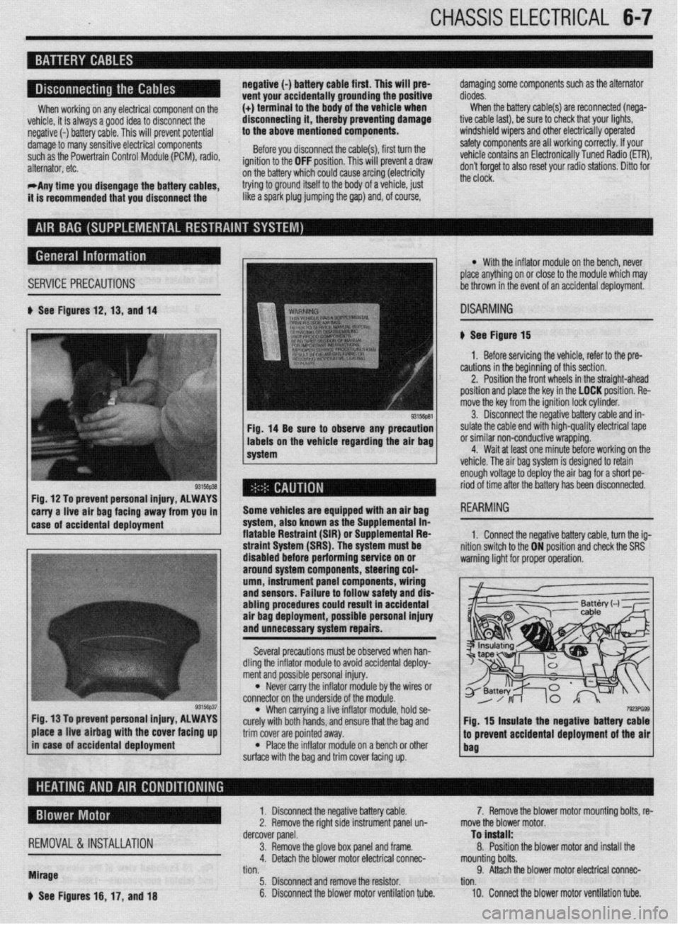
b See Figures 12,13, and 14
Fig, 14 Be sure to observe any precaution
labels on the vehicle regarding the air bag
system
Fig. 12 To prevent personal injury, ALWAYS
*
carry a-live -ah bag fac!ng away from you in 1
1 case of accidental deployment Some vehicles are equipped wtth an air bag
-.-‘--
syr1em, aiscl Known as I11 -I-- ‘------- -- sLe Supplemental in- fiatable Restraint (SIR) o r Suouiementai Fiea
l With the inflator module on the bench, never
place anything on or close to the module which may
be thrown in the event of an accidental deployment.
DISARMING
# See Figure 15
1. Before servicing the vehicle, refer to the pre-
cautions in the beginning of this section.
2. Position the front wheels in the straight-ahead
position and place the key in the LOCK position. Re-
move the key from the ignition lock cylinder.
3. Disconnect the negative battery cable and in-
sulate the cable end with high-quality electrical tape
or similar non-conductive wrapping.
4. Wait at least one minute before working on the
vehicle. The air baa svstem is desianed to retain
enough voltage to deploy the air bag for a short pe-
riod of time after the battery has been disconnected.
1. Connect the neoative batters cable. turn the ia-
3, hold se-
e bag and
trim cover are pointed away.
l Place the inflator module on a bench or other
surface with the bag and trim cover facing up.
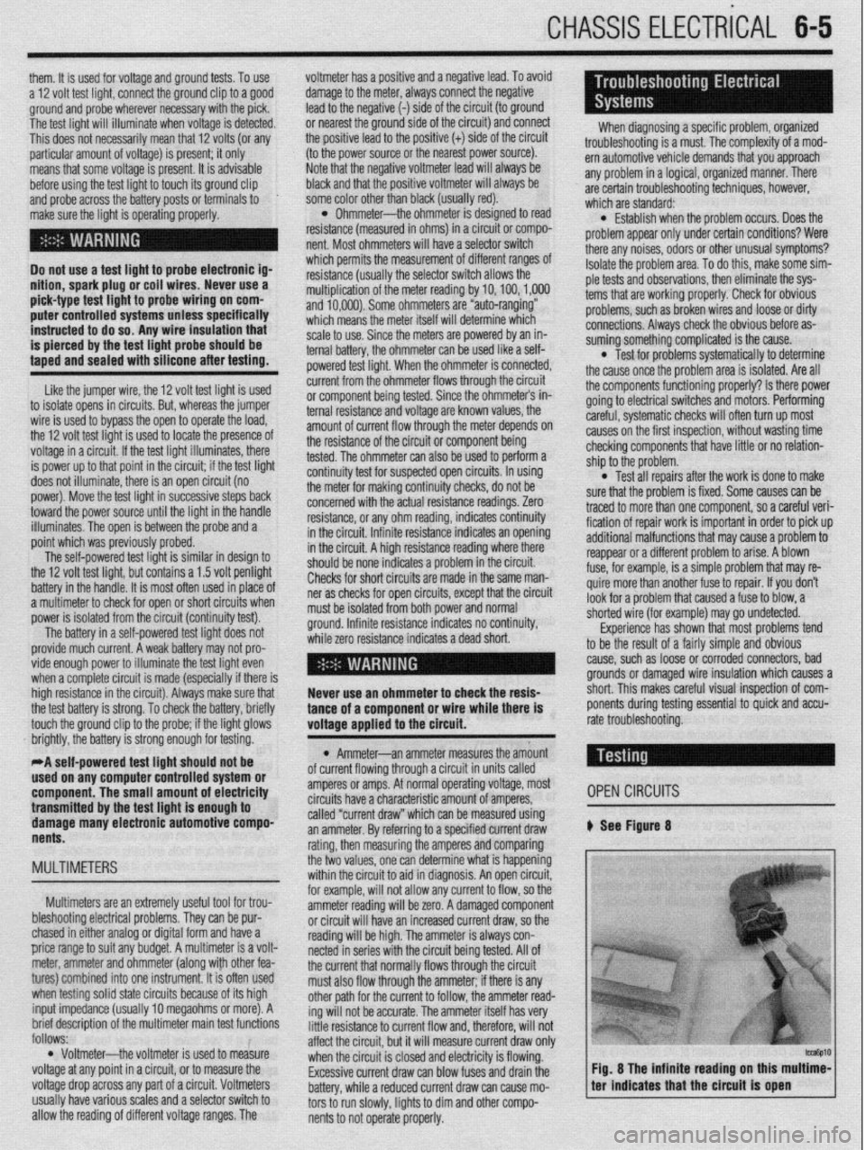
7!r!3PG93 Fig. 15 insulate the negative battery cable
.I
to prevent accidental deployment of the air
bag place a live airbag with the cover facing up
in case of accidental deployment
REMOVAL &INSTALLATION
Mirage
b See Figures 16, 17, and 18 1. Disconnect the negative battery cable.
2. Remove the right side instrument panel un-
dercover panel.
3. Remove the glove box panel and frame.
4. Detach the blower motor electrical connec-
tion.
5. Disconnect and remove the resistor.
6. Disconnect the blower motor ventilation tube. 7. Remove the blower motor mounting bolts, re-
move the blower motor.
To install:
8. Position the blower motor and install the
mounting bolts.
9. Attach the blower motor electrical connec-
tion.
10. Connect the blower motor ventilation tube.