fuel pressure MITSUBISHI DIAMANTE 1900 Repair Manual
[x] Cancel search | Manufacturer: MITSUBISHI, Model Year: 1900, Model line: DIAMANTE, Model: MITSUBISHI DIAMANTE 1900Pages: 408, PDF Size: 71.03 MB
Page 8 of 408
GENERALINFORMATIONAND MAINTENANCE l-9
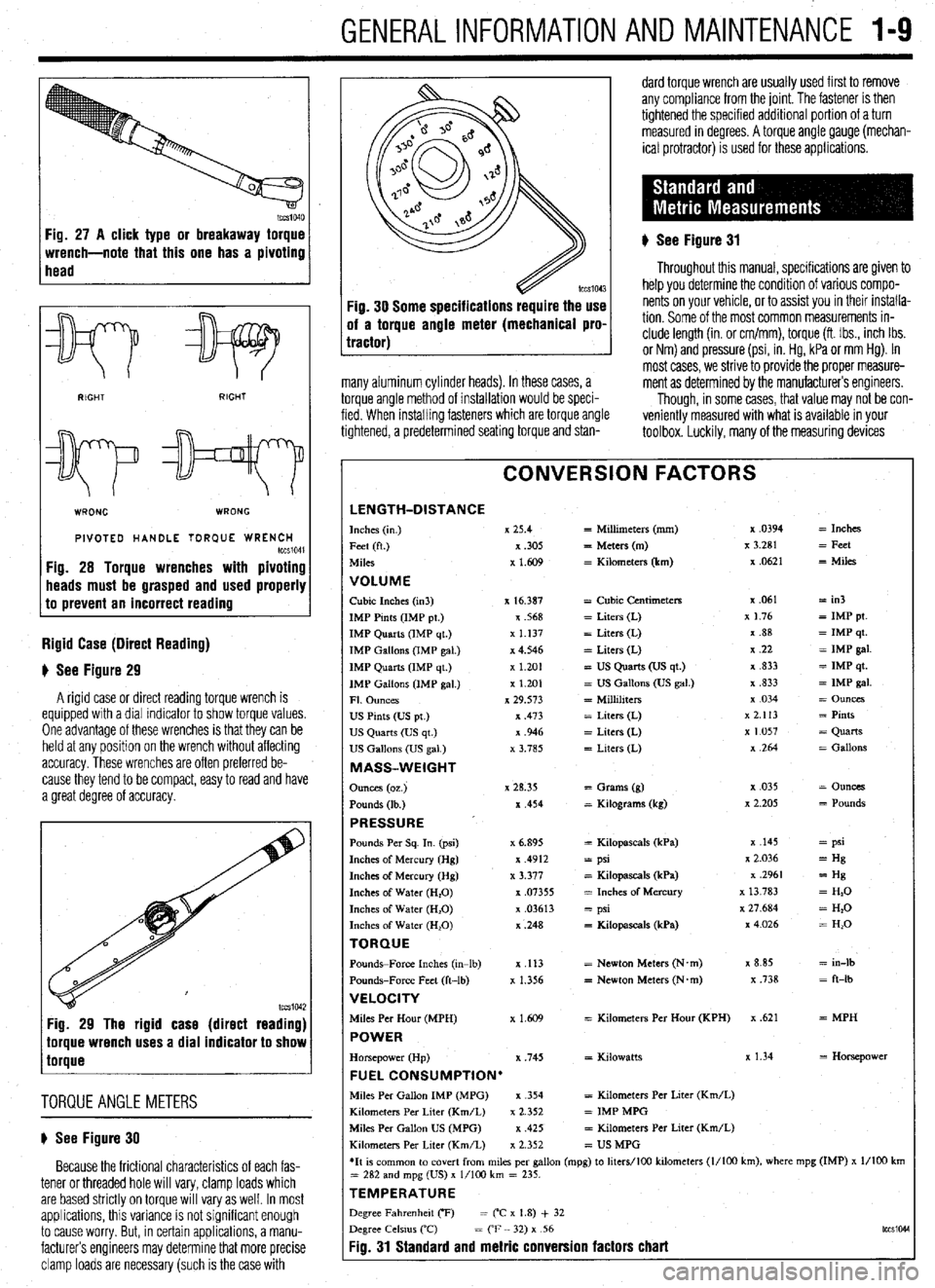
Fig. 27 A click type or breakaway torque
wrench-note that this one has a pivoting
head
v
WRONG WRONG
PIVOTED HANDLE TOR(IUE WRENCH tccS1041 Fig. 28 Torque wrenches with pivoting
heads must be grasped and used properly
to prevent an incorrect reading
Rigid Case (Direct Reading)
# See Figure 29
A rigid case or direct reading torque wrench is
equipped with a dial indicator to show torque values.
One advantage of these wrenches is that they can be
held at any position on the wrench without affecting
accuracy. These wrenches are often preferred be-
cause they tend to be compact, easy to read and have
a great degree of accuracy.
lccs1042 Fig. 29 The rigid case (direct reading)
torque wrench uses a dial indicator to show
torque
TORQUEANGLEMETERS
# See Figure 30
Because the frictional characteristics of each fas-
tener or threaded hole will vary, clamp loads which
are based strictly on torque will vary as well. In most
applications, this variance IS not significant enough
to cause worry. But, in certain applications, a manu-
facturers engineers may determine that more precise
clamp loads are necessary (such is the case with :ig. 30 Some specifications require the use
rf a torque angle meter (mechanical pro.
ractor)
many aluminum cylinder heads). In these cases, a
torque angle method of installation would be speci-
fied. When installing fasteners which are torque angle
tightened, a predetermined seating torque and stan- dard torque wrench are usually used first to remove
any compliance from the joint. The fastener is then
tightened the specified additional portion of a turn
measured in degrees. A torque angle gauge (mechan-
ical protractor) is used for these applications.
) See Figure 31
Throughout this manual, specifications are given to
help you determine the condition of various compo-
nents on your vehicle, or to assist you in their installa-
tion. Some of the most common measurements in-
clude length (in. or cm/mm), torque (ft. Ibs., inch Ibs.
or Nm) and pressure (psi, in. Hg, kPa or mm Hg). In
most cases, we strive to provide the proper measure-
ment as determined by the manufacturers engineers.
Though, in some cases, that value may not be con-
veniently measured with what is available in your
toolbox. Luckily, many of the measuring devices
CONVERSION FACTORS
LENGTH-DISTANCE Inches (I”.) x 25.4 = Millimeters (mm) x .0394 = Inches
Feet (ft.) x ,305
= Meters (m) x 3.281 = Feet
Miles x 1.609 = Kilometers (km) x .0621
= Miles
VOLUME Cubic Inches (in3) x 16.387 = Cubic Centimeters x .061 = in3
IMP Pints (IMP pt.) x .568 = Liters (L) x 1.76
= IMP pt.
IMP Quarts (IMP qt.) x 1.137 = Liters (L) x .88 = IMP qt.
IMP Gallons (IMP gal.) x 4.546 = Liters (L) 7, .22
= IMP gal.
IMP Quarts (IMP qt ) x 1.201 = US Quarts (US qt.) x ,833 = IMP qt.
IMP Gallons (IMP gal.) x 1.201
= US Gallons (US gal.) x ,833
= IMP gal.
Fl. Ounces x 29.573 = Millihters x 034
= Ounces
us Pints (Us pt.) x ,473 = Liters (L) x 2.113 = Pints
US Quarts (US qt.) x .946 = Liters (L) x 1.057
= Quarts
US Gallons (US gal.) x 3.785 = Liters (L) x ,264 = Gallons
MASS-WEIGHT
Ounces (oz.) x 28.35
= Grams (g) x ,035
= Ounces
Pounds (lb ) x ,454 = Kdograms (kg) x 2.205
= Pounds
PRESSURE ’ Pounds Per Sq. In. (psi) x 6.895 = Kilopascals (kPa) x ,145 = psi
Inches of Mercury (Hg) x .4912
= psi x 2.036 = Hg
Inches of Mercury (Hg) x 3.377 = Kilopascals (kPa) x .2961
= Hg
Inches of Water (H,O)
x .07355 = Inches of Mercury x 13 783 = H,O
Inches of Water (H,O) x .03613 = psi x 27.684
= Hz0
Inches of Water (H,O) x ,248
= Kilopascals (kPa) x4026
= H,O
TORQUE Pounds-Force Inches (in-lb)
x ,113 = Newton Meters (N.m) x 8.85 = in-lb
Pounds-Force Feet (ft-lb)
x 1.356 = Newton Meters (N*m) x ,738 = ft-lb
VELOCITY Miles Per Hour (MPH)
x 1.609 = Kilometers Per Hour (KPH) x .621 = MPH POWER Horsepower (Hp) x ,745 = Kdowatts x 1.34
= Horsepower FUEL CONSUMPTION’ Mdes Per Gallon IMP (MPG) x .354
= Kilometers Per Liter (Km/L)
Kilometers Per Liter (Km/L)
x 2.352 = IMP MPG
Miles Per Gallon US (MPG) x ,425
= Kilometers Per Liter (Km/L)
Kdometers Per Liter (Km/L) x 2.352
= US MPG
*It 1s common to covert from miles per gallon (mpg) to hters/lOO kilometers (l/100 km), where mpg (IMP) x l/ID0 km
= 282 and mpg (US) x l/lo0 km = 235.
TEMPERATURE Degree Fahrenheit CF) = (“C x 1.8) + 32
Degree Celsms (‘C)
= CF - 32) x 56
tccsio4d
Fig. 31 Standard and metric conversion factors chart
Page 12 of 408
GENERALINFORMATIONAND MAlNTENANdE 1-13
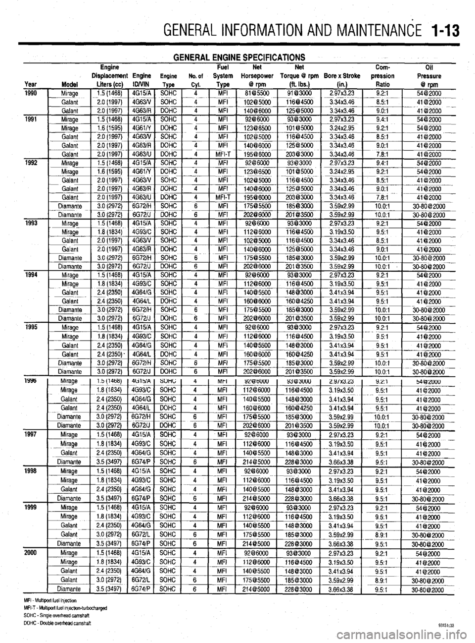
Engine GENERAL ENGINE SPECIFICATIONS Fuel Net Net
Com-
Oil
Displacement Engine Engine No. of System Horsepower Torque @ rpm Bore x Stroke pression
Pressure
MFI Mult+wt fuel mfectw,
MFI-T - Multlporl fuel mfectlon-turbocharged
SOHC - Smgle overhead camshaft
DOHC - Double OvedEad camshaft
Page 14 of 408
GENERALINFORMATIONAND MAINTENANCE l-15
10. install the air cleaner assembly and the re- *Wrap shop towels around the fitting that is
tainer bolts. being dtsconnected to absorb residual fuel in
11. Connect the air intake hose. the lines. 9. While holding the fuel filter nut with aback-
up wrench, tighten the banjo bolt to 22 ft. Ibs. (30
Nm). Tighten the flare nut to 25 ft. Ibs. (35 Nm), with
12. Attach the solenoid valve.
4. Cover the hose connection with shop towels to a back-up wrench on the nut.
13. Connect the boost hose.
14. Attach the air flow sensor connector. prevent any splash of fuel that could be caused by 10. Tighten the filter mounting bolts to 10 ft. Ibs.
residual pressure in the fuel pipe line. Hold the fuel (14 Nm).
15. Connect the negative battery cable. 11.
filter nut securely with a backup wrench, then remove Connect the negative battery cable. Turn the
REMOVAL &INSTALLATION the banjo bolt on the engine feed line. Disconnect the
high-pressure fuel line from the filter. Remove and
discard the gaskets.
5. While holding the fuel filter nut securely with a
back-up wrench, loosen the filter feed pipe flare nut key to the ON position to pressurize the fuel system
and check for leaks.
12. If repairs of a leak are required, remember to
release the fuel pressure before opening the fuel sys-
tern.
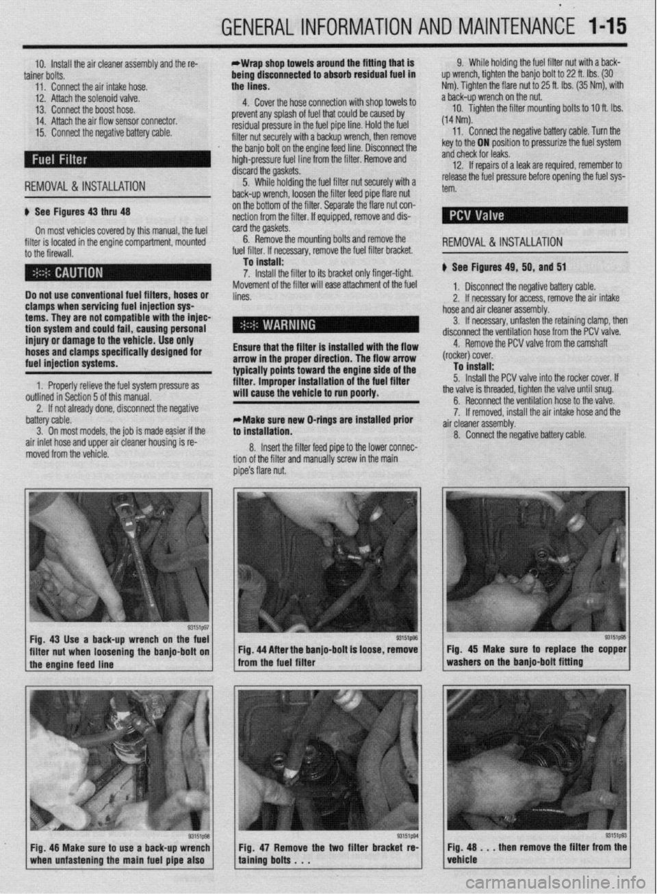
u See Figures 43 thru 48
On most vehicles covered by this manual, the fuel
filter is located in the engine compartment, mounted
to the firewall.
Do not use conventional fuel filters, hoses or
clamps when servicing fuel injection sys
terns. They are not compatible with the injec-
tion
system and could fail, causing personal
injury or damage to the vehicle. Use only
hoses and clamps specifically designed for
fuel injection systems.
1. Properly relieve the fuel system pressure as
outlined in Section 5 of this manual. on the bottom of the filter. Separate the flare nut con-
nection from the filter. If equipped, remove and dis-
card the gaskets.
6. Remove the mounting bolts and remove
. ,,,. ,.
.a r I,.,< I the
ruer rrrter. II necessary, remove me ruer rrrrer oracket.
To install:
7. Install the filter to its bracket only finger-tight.
Movement of the filter will ease attachment of the fuel
lines.
Ensure that the filter is installed with the flow
arrow in the proper direction. The flow arrow
typically points toward the engine side of the
filter. improper installation of the fuel filter
will cause the vehicle to run poorly.
2. If not already done, disconnect the negative REMOVAL&INSTALLATION
u See Figures 49, 50, and 51
1, Disconnect the negative battery cable.
2. If necessary for access, remove the air intake
hose and air cleaner assembly.
3. If necessary, unfasten the retaining clamp, then
disconnect the ventilation hose from the PCV valve.
4. Remove the PCV valve from the camshaft
(rocker) cover.
To install:
5. Install the PCV valve into the rocker cover. If
the valve is threaded, tighten the valve until snug.
battery cable.
3. On most models. the iob is made easier if the
air inlet hose and upper air cleaner housing is re-
moved from the vehicle. *Make sure new O-rings are installed prior
to installation.
8. Insert the filter feed pipe to the lower connec-
tion of the filter and manually screw in the main
pipe’s flare nut. 6. Reconnect the ventilation hose to the valve.
7. If removed, install the air intake hose and the
a .ir cleaner assembly.
8. Connect the negative battery cable.
Fig. 43 Use a back-up wrench on the fuel
I I
93151@3
filter nut when loosening the banjo-bolt on Fig. 44 After the banjo-bolt is loose, remove
I
1 the engine feed line - from the fuel filter
93151p93 Fig. 48 Make sure to use a back-up wrench
1 when unfastening the main fuel pipe also 1 Fig. 47 Remove the two filter bracket re-
taining bolts . . . Fig. 45 Make sure to replace the copper
washers on the banjo-bolt fitting
Fig. 48 . . . then remove the filter from the
vehicle
Page 27 of 408
l-28 GENERALINFORMATIONAND MAINTENANCE
may result in skin or eye irritation or frostbite. Al- formed to help maintain the efficiency of the vehicle’s
though low in toxicity (due to chemical stability), in- A/C system. For preventive maintenance, perform the
The idle speed is factory set and usually no ad- halation of concentrated refrigerant fumes is danger- following:
justments are ever necessary. If an adjustment be- ous and can result in death; cases of fatal cardiac
l The easiest and most important preventive
comes necessary, first check that the spark plugs, in- arrhythmia have been reported in people accidentally maintenance for your A/C system is to be sure that it
jectors, idle air control servo and compression subjected to high levels of refrigerant. Some early is used on a regular basis. Running the system for
pressure are all normal. symptoms include loss of concentration and drowsi- five minutes each month (no matter what the season)
Data from various sensors and switches are used ness. + will help ensure that the seals and all internal compo-
by the ECU to determine the proper fuel/air mixture
for optimal engine performance. cGeneraiiy, the limit for exposure is lower nents remain lubricated.
for R-134a than it is for R-12. Exceptional *Some newer vehicles automatically oper-
care must be practiced when handling R- ate the A/C system compressor whenever the
134a. windshield defroster is activated. When run-
Also, refrigerants can decompose at high tempera- ning, the compressor lubricates the A/C sys
tures (near gas heaters or open flame), which may re- tern components; therefore, the A/C system
SYSTEM SERVICE& REPAIR suit in hydrofluoric acid, hydrochloric acid and phos- would not need to be operated each month.
gene (a fatal nerve gas). * In order to prevent heater core freeze-up during
R-12 refrigerant can damage the environment be- A/C operation, it is necessary to maintain proper an-
cause it is a Chlorofluorocarbon (CFC), which has tifreeze protection. Use a hand-held coolant tester
been proven to add to ozone layer depletion, leading (hydrometer) to periodically check the condition of
to increasing levels of UV radiation. UV radiation has the antifreeze in your engine’s cooling system.
been linked with an increase in skin cancer, suppres-
sion of the human immune system, an increase in *Antifreeze should not be used longer than
cataracts, damage to crops, damage to aquatic organ- the manufacturer specifies.
isms, an increase in ground-level ozone, and in- . For efficient operation of an air conditioned ve-
creased global warming. hicle’s cooling system, the radiator cap should have a
R-134a refrigerant is a greenhouse gas which, if holding pressure which meets manufacturers specifi-
allowed to vent into the atmosphere, will contribute to cations. A cap which fails to hold these pressures
global warming (the Greenhouse Effect). should be replaced.
It is usually more economically feasible to have a
l Any obstruction of or damage to the condenser
certified MVAC automotive technician perform A/C configuration will restrict air flow which is essential
system service on your vehicle. Some possible rea- to its efficient operation. It is, therefore, a good rule
sons for this are as follows: to keep this unit clean and in proper physical shape.
l While it is illegal to service an A/C system
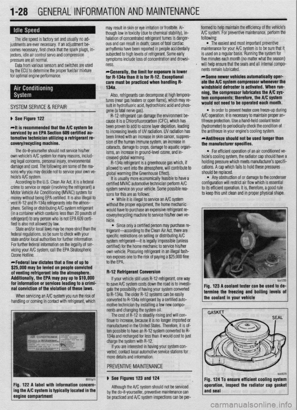
without the proper equipment, the home mechanic ti See Figure 122
*it is recommended that the A/C svstem be
serviced by an EPA Section 609 cehified au-
tomotivetechnicfan utilizing a refrigerant re-
covery/recycling machfne.
The do-it-yourselfer should not service his/her
own vehicle’s A/C system for many reasons, includ-
ing legal concerns, personal injury, environmental
damage and cost. The following are some of the rea-
sons why you may decide not to service your own ve-
hicle’s A/C system.
According to the U.S. Clean Air Act, it is a federal
crime to service or repair (involving the refrigerant) a
Motor Vehicle Air Conditioning (MVAC) system for
money without being EPA certified. It is also illegal to
vent R-12 and R-134a refrigerants into the atmos-
phere. Selling or distributing A/C system refrigerant
(in a container which contains less than 20 pounds oi
refrigerant) to any person who is not EPA 609 certi-
fied is also not allowed by law.
State and/or local laws may be more strict than the
federal regulations, so be sure to check with your
state and/or local authorities for further information.
For further federal information on the legality of ser-
vicing your AK system, call the EPA Stratospheric
Ozone Hotline.
*Federal law dictates that a fine of up to
$25,000 may be levied on people convicted
of venting refrigerant into the atmosphere.
Additionally, the EPA may pay up to $10,000
for information or services leading to a crimf
nai conviction of the violation of these laws.
When servicing an A/C system you run the risk of
handling or coming in contact with refrigerant, which
Fig. 122 A label with information concern-
ing the A/C system is typically located in the
engine compartment
f would haveto purchase an expensive refrigerant re-
covery/recycling machine to service his/her own ve-
hicle.
l Since only a certified person may purchase re-
frigerant-according to the Clean Air Act, there are
specific restrictions on selling or distributing A/C
system refrigerant-it is legally impossible (unless
certified) for the home mechanic to service his/her
own vehicle. Procuring refrigerant in an illegal fash-
ion exposes one to the risk of paying a $25,000 fine
to the EPA.
R-12 Refrigerant Conversion
If your vehicle still uses R-12 refrigerant, one
way to save A/C system costs down the road is to invesh-
gate the possibility of having your system converted
to R-134a. The older R-12 systems can be easily
converted to R-134a refrigerant by a certified auto-
motive technician by installing a few new compo-
nents and changing the system oil.
The cost of R-12 is steadily rising and will con-
tinue to increase, because it is no longer imported or
manufactured in the United States. Therefore, it is of-
ten possible to have an R-12 system converted to R-
134a and recharged for less than it would cost to just
charge the system with R-12.
If you are interested in having your system con-
verted, contact local automotive service stations for
more details and information.
u See Figures 123 and 124
Although the A/C system should not be serviced
by the do-it-yourselfer, preventive maintenance can
be practiced and A/C system inspections can be per- Fig. 123 A coolant tester can be used to de-
1 termine the freezing and boiling levels of
the coolant in your vehicle
Fig. 124 To ensure efficient cooling system
operation, inspect the radiator cap gasket
and seal
Page 31 of 408
.
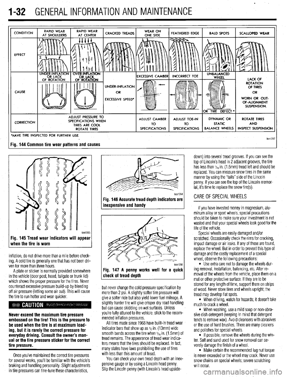
1-32 GENERALINFORMATIONAND MAINTENANCE
CONDITION
EFFECT
CAUSE
CORRECTION UNDER-INFLATION
EXCESSIVE SPEED’ WORN OR OUT-
OF-ALIGNMENT
ADJUST PRESSURE TO
SPECIFICATIONS WHEN
TIRES ARE COOL
ROTATE TIRES
/ BALANCE WHEELS INSPECT SUSPENSION
HAVE TIRE INSPECTED FOR FURTHER USE.
lCCSi267 ig. 144 Common tire wear patterns and causes
1~~~1265 Fig. 145 Tread wear indicators will appear
when the tire is worn
inflation, do not drive more than a mile before check-
ing. A cold tire is generally one that has not been dri-
ven for more than three hours.
A plate or sticker is normally provided somewhere
in the vehicle (door post, hood, tailgate or trunk lid)
which shows the proper pressure for the tires. Never
counteract excessive pressure build-up by bleeding
off air pressure (letting some air out). This will cause
the tire to run hotter and wear quicker.
Never exceed the maximum tire pressure
embossed on the tire! This is the pressure to
be used when the tire is at maximum load-
ing, but it is rarely the correct pressure for
everyday driving. Consult the owner’s man-
ual or the tire pressure sticker for the correct
tire pressure.
Once you’ve maintained the correct tire pressures
for several weeks, you’ll be familiar with the vehicle’s
braking and handling personality. Slight adjustments
in tire pressures can fine-tune these characteristics,
1~~~1264 Fig. 146 Accurate tread depth indicators are
inexuensive and handv
Fig. 147 A penny works well for a quick
check of tread death
but never change the cold pressure specification by
more than 2 psi. A slightly softer tire pressure will
give a softer ride but also yield lower fuel mileage. A
slightly harder tire will give crisper dry road handling
but can cause skidding on wet surfaces. Unless
you’re fully attuned to the vehicle, stick to the recom-
mended inflation pressures.
All tires made since 1968 have built-in tread wear
indicator bars that show up as j/2 in. (13mm) wide
smooth bands across the bre when V,~ in. (1.5mm) of
tread remains. The appearance of tread wear indica-
tors means that the tires should be replaced. In fact,
many states have laws prohibiting the use of tires
with less than this amount of tread.
You can check your own tread depth with an inex-
pensive gauge or by using a Lincoln head penny.
Shp the Lrncoln penny (with Lincoln’s head upside- down) into several tread grooves. If you can see the
top of Lincoln’s head in 2 adjacent grooves, the tire
has less than V,~ in. (1.5mm) tread left and should be
replaced. You can measure snow tires in the same
manner by using the “tails” side of the Lincoln
penny. If you can see the top of the Lincoln memor-
ial, its time to replace the snow tire(s).
CAREOFSPECIALWHEELS
If you have invested money in magnesium, alu-
minum alloy or sport wheels, special precautions
should be taken to make sure your investment is not
wasted and that your special wheels look good for the
life of the vehicle.
Special wheels are easily damaged and/or
scratched. Occasionally check the rims for cracking,
impact damage or air leaks. If any of these are found,
replace the wheel. But in order to prevent this type of
damage and the costly replacement of a special
wheel, observe the following precautions:
l Use extra care not to damage the wheels dur-
ing removal, installation, balancing, etc. After re-
moval of the wheels from the vehicle, place them on a
mat or other protective surface. If they are to be
stored for any length of time, support them on strips
of wood. Never store tires and wheels upright; the
tread may develop flat spots.
l When driving, watch for hazards; it doesn’t take
much to crack a wheel.
l When washing, use a mild soap or non-abra-
sive dish detergent (keeping in mind that detergent
tends to remove wax). Avoid cleansers with abrasives
or the use of hard brushes. There are many cleaners
and polishes for special wheels.
l If possrble, remove the wheels during the win-
ter. Salt and sand used for snow removal can se-
verely damage the finish of a wheel.
l Make certain the recommended lug nut torque
is never exceeded or the wheel may crack. Never use
snow chains on special wheels; severe scratching
will occur.
Page 63 of 408
3-2 ENGINEANDENGINEOVERHAUL
REMOVAL &INSTALLATION
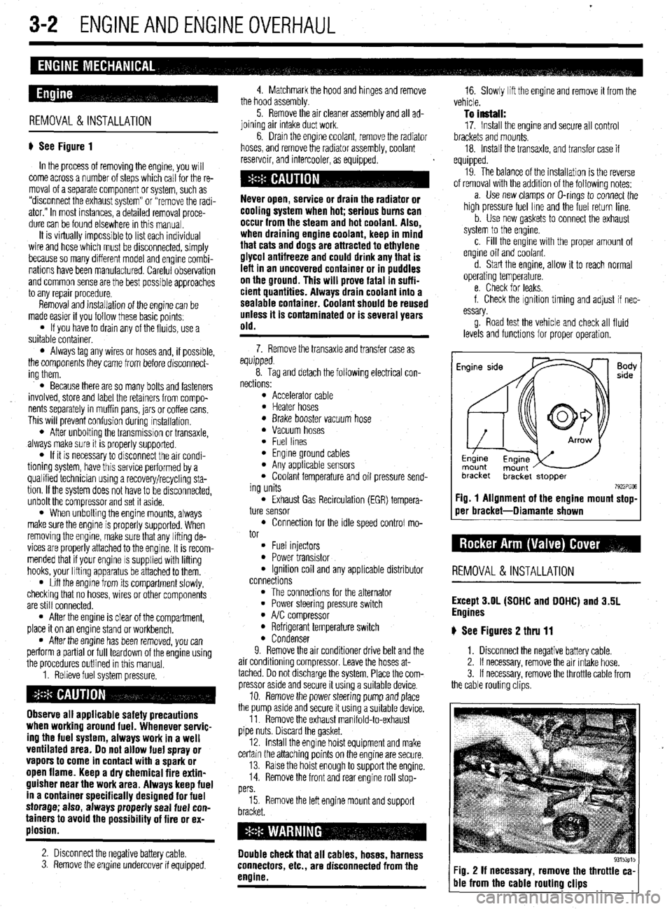
# See Figure 1
In the process of removing the engine, you will
come across a number of steps which call for the re-
moval of a separate component or system, such as
“disconnect the exhaust system” or “remove the radi-
ator.” In most instances, a detailed removal proce-
dure can be found elsewhere in this manual.
It is virtually impossible to list each individual
wire and hose which must be disconnected, simply
because so many different model and engrne combi-
nations have been manufactured Careful observation
and common sense are the best possible approaches
to any repair procedure.
Removal and installation of the engine can be
made easier if you follow these basic points:
l If you have to drain any of the fluids, use a
suitable container.
l Always tag any wires or hoses and, if possrble,
the components they came from before disconnect-
ing them.
l Because there are so many bolts and fasteners
involved, store and label the retainers from compo-
nents separately in muffin pans, jars or coffee cans.
This will prevent confusion during installatron.
l After unbolting the transmisston or transaxle,
always make sure it is properly supported.
l If it is necessary to disconnect the air condi-
tioning system, have this service performed by a
qualified technician using a recovery/recycling sta-
tion If the system does not have to be disconnected,
unbolt the compressor and set it aside.
l When unbolting the engine mounts, always
make sure the engine is properly supported. When
removing the engine, make sure that any lifting de-
vices are properly attached to the engine. It is recom-
mended that if your engine IS supplied with lifting
hooks, your lifting apparatus be attached to them.
l Lift the engine from its compartment slowly,
checking that no hoses, wires or other components
are still connected.
l After the engine is clear of the compartment,
place it on an engine stand or workbench.
l After the engine has been removed, you can
perform a partial or full teardown of the engine using
the procedures outlined in this manual.
1. Relieve fuel system pressure.
Observe all applicable safety precautions
when working around fuel. Whenever servic-
ing the fuel system, always work in a well
ventilated area. Do not allow fuel spray or
vapors to come in contact with a spark or
open flame. Keep a dry chemical fire extin-
guisher near the work area. Always keep fuel
in a container specifically designed for fuel
storage; also, always properly seal fuel con-
tainers to avoid the possibility of fire or ex-
plosion.
2. Disconnect the negative battery cable.
3. Remove the engine undercover if equipped. 4. Matchmark the hood and hinges and remove
the hood assembly.
5. Remove the air cleaner assembly and all ad-
joining air intake duct work.
6. Drain the engine coolant, remove the radiator
hoses, and remove the radiator assembly, coolant
reservoir, and intercooler, as equipped.
cooling system when hot; serious burns can
occur from the steam and hot coolant. Also,
when draining engine coolant, keep in mind
that cats and dogs are attracted to ethylene
glycol antifreeze and could drink any that is
left in an uncovered container or in puddles
on the ground. This will prove fatal in suffi-
cient quantities. Always drain coolant into a
sealable container. Coolant should be reused
unless it is contaminated or is several years
old.
7. Remove the transaxle and transfer case as
equipped.
8. Tag and detach the following electrical con-
nections:
l Accelerator cable l Heater hoses l Brake booster vacuum hose l Vacuum hoses l Fuel lines l Engine ground cables l Any applicable sensors l Coolant temperature and oil pressure send-
ing units
l Exhaust Gas Recirculation (EGR) tempera-
ture sensor
l Connection for the idle speed control mo-
tor
l Fuel injectors l Power transistor l Ignition coil and any applicable distributor
connections
l The connections for the alternator l Power steering pressure switch l A/C compressor l Refrigerant temperature switch l Condenser
9. Remove the air conditioner drive belt and the
air conditioning compressor. Leave the hoses at-
tached. Do not discharge the system. Place the com-
pressor aside and secure it using a suitable device.
10. Remove the power steering pump and place
the pump asrde and secure it using a surtable device.
11. Remove the exhaust manifold-to-exhaust
pipe nuts. Discard the gasket.
12. Install the engine hoist equipment and make
certain the attaching points on the engine are secure.
13. Raise the hoist enough to support the engine.
14. Remove the front and rear engine roll stop-
pers
15. Remove the left engine mount and support
Double check that all cables, hoses, harness
connectors, etc., are disconnected from the
engine.
16. Slowly lift the engine and remove it from the
vehicle.
To install:
17. Install the engine and secure all control
brackets and mounts.
18. Install the transaxle, and transfer case if
equipped.
19. The balance of the installation is the reverse
of removal with the addition of the following notes:
a. Use new clamps or O-rings to connect the
high pressure fuel lme and the fuel return line.
b. Use new gaskets to connect the exhaust
system to the engine.
c. Fill the engine with the proper amount of
engine oil and coolant.
d. Start the engine, allow it to reach normal
operating temperature.
e. Check for leaks.
f. Check the ignition timing and adjust if nec-
essary.
g. Road test the vehicle and check all fluid
levels and functions for proper operation.
Fig. 1 Alignment of the engine mount stop-
oer bracket-Diamante shown
REMOVAL &INSTALLATION
Except 3.OL (SOHC and DOHC) and 3.5L
Engines
# See Figures 2 thru 11
1. Disconnect the negative battery cable.
2. If necessary, remove the air intake hose.
3. If necessary, remove the throttle cable from
the cable routing clips.
Fig. 2 If necessary, remove the throttle ca-
ble from the cable routing clips
Page 67 of 408
.
3-6 ENGINEANDENGINEOVERHAUL
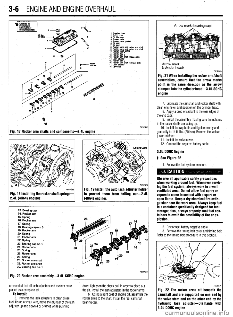
I Fig. 17 Rocker arm shafts and components-2.41 engine
Fig. 18 Installing the rocker shaft springs- 79231632
13. Bearing cap
14. Rocker arm
15. spring
16. Rocker arm
17. Spring
16 Bearing no. cap 3
IQ. Rocker arm
20. spring
21. Rocker arm
22. Spring
23. Bearing no. cap 2
24. Rocker arm
25. spring
26. Rocker arm
27. Spring
28. Rocker arm shaft
29. Rocker arm shaft
30. Bearing no. cap 1
Fig. 20 Rocker arm assembly-3.01 SOHC engine 7923PG3
ommended that all lash adjusters and rockers be re-
placed as a complete set.
To install:
5. Immerse the lash adjusters in clean diesel
fuel. Using a small wire, move the plunger of the lash
adjuster up and down 4 or 5 times while pushing down lightly on the check ball in order to bleed out
the air. Install the lash adjusters in the rocker arms.
6. Using a light coat of engine oil, assemble the
rocker arms to the shaft. Install the rear camshaft
bearing cap.
Arrow mark (bearing cap)
Arrow mark
fcyllnder head)
7923PG35 Fig. 21 When installing the rocker arm/shafi
assemblies, ensure that the arrow marks
point in the same direction as the arrow
stamped into the cylinder head-3.01 SOHC
engine
7. Lubricate the camshaft and rocker shaft with
clean engine oil and position on the cylinder head.
8. Apply a drop of sealant to the rear edges of
the end caps.
9. Install the assembly making sure the notches
in the rocker shafts are facing up.
10. Install the cap bolts and tighten evenly and
gradually to 14 ft. Ibs. (20 Nm). Remove the lash ad-
juster retainers
11. Install the valve cover.
12. Connect the negative battery cable.
3.OL OOHC Engine
) See Figure 22
1. Relieve the fuel system pressure.
Observe all applicable safety precautions
when working around fuel. Whenever servic-
ing the fuel system, always work in a well
ventilated area. 00 not allow fuel spray or
vapors to come in contact with a spark or
open flame. Keep a dty chemical fire extin-
guisher near the work area. Always keep fuel
in a container specifically designed for fuel
storage; also, always properly seal fuel con-
tainers to avoid the possibility of fire or ex-
plosion.
2. Disconnect battery negative cable.
3. Remove the timino belt cover and timina belt.
Refer to the timing belt procedure in this section.
7923PG3 Fig. 22 The rocker arms sit beneath the
camshaft and are supported on one end bl
the valve stem and on the other end by the
hydraulic lash adjuster-Oiamante wit1
3.OL OOHC engine
Page 69 of 408
3-8' ENGINEANDENGINEOVERHAUL
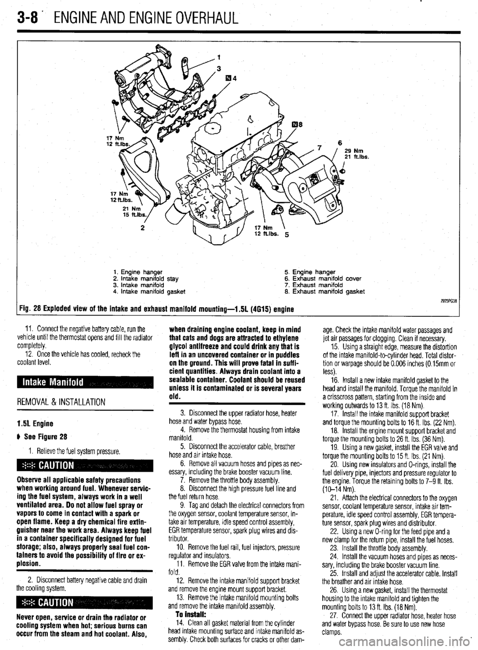
Nm ft.lbs.
1. Engine hanger 5. Engine hanger
2. Intake manifold stay 6. Exhaust manifold cover
3. intake manifold 7. Exhaust manifold
4. Intake manifold gasket 8. Exhaust manifold gasket
7923ffi38 :ig. 28 Exploded view of the intake and exhaust manifold mounting-l .5L (4615) engine
11. Connect the negative battery cable, run the ,. . . .
vemcie unnl me tnermostat opens ano till the radiator
completely. age. Check the intake manifold water passages and
jet air passages for clogging. Clean if necessary.
12. Once the vehicle has cooled, recheck the
coolant level.
REMOVAL &INSTALLATION when draining engine coolant, keep in mind
that cats and dogs are attracted to ethylene
glycol antifreeze and could drink any that is
left in an uncovered container or in puddles
on the ground. This will prove fatal In suffi-
cient quantities. Always drain coolant into a
sealable container. Coolant should be reused
unless it is contaminated or is several years
old.
15. Using a straight edge, measure the distortion
of the intake manifold-to-cylinder head. Total distor-
tion or warpage should be 0.006 inches (0.15mm or
less).
16. Install a new intake manifold gasket to the
head and install the manifold. Torque the manifold in
a crisscross pattern, starting from the inside and
working outwards to 13 ft. Ibs. (18 Nm).
17. Install the intake manifold support bracket
and torque the mounting bolts to 16 ft. Ibs. (22 Nm).
18. Install the engine mount support bracket and
torque the mounting bolts to 26 ft. Ibs. (36 Nm).
19. Using a new gasket, install the EGR valve and
torque the mounting bolts to 15 ft. Ibs. (21 Nm).
20. Using new insulators and O-rings, install the
fuel delivery pipe, injectors and pressure regulator to
the engine. Torque the retaining bolts to 7-9 ft. Ibs.
(10-14 Nm).
1.51 Engine
# See Figure 28
1. Relieve the fuel system pressure.
Observe all applicable safety precautions
when working around fuel. Whenever servic-
ing the fuel system, always work in a well
ventilated area. Do not allow fuel spray or
vapors to come in contact with a spark or
open flame. Keep a dry chemical fire extin-
guisher near the work area. Always keep fuel
in a container specifically designed for fuel
storage; also, always properly seal fuel con-
tainers to avoid the possibility of fire or ex-
plosion.
2. Disconnect battery negative cable and drain
the cooling system.
Never open, service or drain the radiator or
cooling system when hot; serious burns can
occur from the steam and hot coolant. Also,
3. Disconnect the upper radiator hose, heater
hose and water bypass hose.
4. Remove the thermostat housing from intake
manifold.
5. Disconnect the accelerator cable, breather
hose and air intake hose.
6. Remove all vacuum hoses and pipes as nec-
essary, including the brake booster vacuum line.
7. Remove the throttle body assembly.
8. Disconnect the high pressure fuel line and
the fuel return hose.
9. Tag and detach the electrical connectors from
the oxygen sensor, coolant temperature sensor, in-
take air temperature, idle speed control assembly,
EGR temperature sensor, spark plug wires and dis-
tributor.
10. Remove the fuel rail, fuel injectors, pressure
regulator and insulators.
11. Remove the EGR valve from the intake mani-
fold.
12. Remove the intake manifold support bracket
and remove the engine mount support bracket.
13. Remove the intake manifold mounting bolts
and remove the intake manifold assembly.
To Install: 14. Clean all gasket material from the cylinder
head intake mounting surface and intake manifold as-
sembly. Check both surfaces for cracks or other dam- 21. Attach the electrical connectors to the oxygen
sensor, coolant temperature sensor, intake air tem-
perature, idle speed control assembly, EGR tempera-
ture sensor, spark plug wires and distributor.
22. Using a new O-ring for the feed pipe and a
new clamp for the return pipe, install the fuel hoses.
23. Install the throttle body assembly.
24. Install the vacuum hoses and pipes as neces-
sary, including the brake booster vacuum line.
25. Install and adjust the accelerator cable. Install
the breather and air Intake hose.
26. Using a new gasket, install the thermostat
housing to the intake manifold and tighten the
mounting bolts to 13 ft. Ibs. (18 Nm).
27. Connect the upper radiator hose, heater hose
and water bypass hose. Be sure to use new hose
clamps.
Page 70 of 408
ENGINEANDENGINEOVERHAUL 3-9
28. Fill the system with coolant.
29. Connect the negative battery cable, run the
vehicle until the thermostat opens, fill the radiator
completely.
30. Check and adjust the idle speed and ignition
timing.
31. Once the vehicle has cooled, recheck the
coolant level.
1.8L Engine
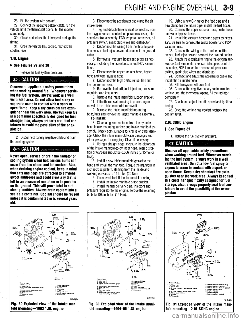
) See Figures 29 and 30
I. Relieve the fuel system pressure.
Observe all applicable safety precautions
when working around fuel. Whenever servic-
ing the fuel system, always work in a well
ventilated area. Do not allow fuel spray or
vapors to come in contact with a spark or
open flame. Keep a dry chemical fire extin-
guisher near the work area. Always keep fuel
in a container specifically designed for fuel
storage; also, always properly seal fuel con-
tainers to avoid the possibility of fire or ex-
plosion.
2. Disconnect battery negative cable and drain
the cooling system.
Never open, service or drain the radiator or
cooling system when hot; serious burns can
occur from the steam and hot coolant. Also,
when draining engine coolant, keep in mind
that cats and dogs are attracted to ethylene
glycol antifreeze and could drink any that is
leff in an uncovered container or in puddles
on the ground. This will prove fatal in suffi-
cient quantities. Always drain coolant into a
sealable container. Coolant should be reused
unless it is contaminated or is several years
old.
Fig. 29 Exploded view of the intake mani.
old mounting-1993 1.8L engine
3. Disconnect the accelerator cable and the air
intake hose.
4. Tag and detach the electrical connectors from
the oxygen sensor, coolant temperature sensor, idle
speed control assembly, EGR temperature sensor, oil
pressure switch, spark plug wires and distributor.
5. Disconnect the wiring from the throttle posi-
tion sensor, fuel Injectors and disconnect the ground
cables.
6. Remove all vacuum hoses and pipes as nec-
essary, including the brake booster and PCV vacuum
lines.
7. Disconnect the upper radiator hose, heater
hose and water bypass hose.
8. Disconnect the high pressure fuel line and
the fuel return hose.
9. Remove the fuel rail, fuel injectors, pressure
regulator and insulators.
10. Remove the intake manifold support bracket.
11. If the thermostat housing is preventing re-
moval of the Intake manifold, remove it.
12. Remove the intake manifold mounting
bolts/nuts and remove the intake manifold assembly.
To install: 13. Clean all gasket material from the cylinder
head intake mounting surface and intake manifold as-
sembly Check both surfaces for cracks or other dam-
age. Check the intake manifold water passages and
jet air passages for clogging. Clean if necessary.
14. Using a straight edge, measure the distortion
of the intake manifold-to-cylinder head. Total distor-
tion or warpage should be 0.006 inches (0.15mm or
less).
15. Install a new intake manifold gasket to the
head and install the manifold. Torque the manifold in
a crrsscross pattern, starting from the inside and
working outwards to 14 ft. Ibs. (20 Nm).
16. If removed, install the thermostat housing.
17. Install the Intake manifold brace bracket.
18. Install the fuel delivery pipe, injectors and
pressure regulator to the engine. Torque the retaining
bolts to 108 Inch Ibs. (12 Nm). 19. Using a new O-ring for the feed pipe and a
new clamp for the return pipe, install the fuel hoses,
20. Connect the upper radiator hose, heater hose
and water bypass hoses.
21. Install the vacuum hoses and pipes as neces-
sary. Be sure to connect the brake booster and PCV
vacuum lines
22. Connect the wiring to the throttle position
sensor, fuel injectors and connect the ground cables,
23. Attach the electrical wiring to the oxygen sen-
sor, coolant temperature sensor, Idle speed control
assembly, EGR temperature sensor, oil pressure
switch, spark plug wires and distributor.
24. Connect and adjust the accelerator cable and
install the air intake hose.
25. Fill the system with coolant.
26. Connect the negative battery cable, run the
vehicle until the thermostat opens, fill the radiator
completely.
27. Check and adjust the idle speed and ignition
timing.
28. Once the vehicle has cooled, recheck the
coolant level. 2.OL SOHC Engine
# See Figure 31
1. Relieve the fuel system pressure.
Observe all applicable safety precautions
when working around fuel. Whenever servic-
ing the fuel system, always work in a well
ventilated area. Do not allow fuel spray or
vapors to come in contact with a spark or
open flame. Keep a dry chemical fire extin-
guisher near the work area. Always keep fuel
in a container specifically designed for fuel
storage; also, always properly seal fuel con-
tainers to avoid the possibility of fire or ex-
plosion.
Fig. 30 Exploded view of the intake mani,
iold mounting-1994-00 1.8L engine Fig. 31 Exploded view of the intake mani
fold mounting-2.01 SOHC ermine
Page 71 of 408
3-10 ENGINEANDENGINEOVERHAUL
2. Disconnect the battery negative cable.
3. Drain the cooling system.
Never open, service or drain the radiator or
cooling system when hot; serious burns can
occur from the steam and hot coolant. Also,
when draining engine coolant, keep in mind
that cats and dogs are attracted to ethylene
glycol antifreeze and could drink any that is
left in an uncovered container or in puddles
on the ground. This will prove fatal in suffi-
cient quantities. Always drain coolant into a
sealable container. Coolant should be reused
unless it is contaminated or is several years
old.
4 Disconnect the accelerator cable and air in-
take hose.
5. Disconnect the upper radiator hose, heater
hose and water bypass hose.
6. Unplug the vacuum connection at the power
brake booster and the PCV valve if still connected.
Disconnect all remaining vacuum hoses and pipes as
necessary.
7. Disconnect the high pressure fuel line, fuel
return hose and remove throttle control cable brack-
ets
8. Tag and detach the electrical connectors from
the oxygen sensor, coolant temperature sensor,
therm0 switch, idle speed control assembly, EGR
temperature sensor, distributor, fuel injectors and
spark plug wires. Position the engine wiring harness
aside.
9. Matchmark the distributor housing to the in-
take manifold, and remove the distributor.
10. Remove the intake manifold bracket and the
engine hanger.
11. If the thermostat housing is preventing re-
moval of the intake manifold, remove it.
12. Remove the intake manifold mounting bolts
and remove the intake manifold assembly. Drsassem-
ble manifold from the Intake plenum on a work bench
as required
To install: 13. Clean all gasket material from the cylinder
head intake mounting surface and intake manifold as-
sembly. Check both surfaces for cracks or other dam-
age. Check the intake manifold water passages and
jet air passages for clogging. Clean if necessary.
14 Assemble the intake manifold assembly using
all new gaskets. Torque air intake plenum bolts to
11-14ff. Ibs. (15-19 Nm).
15. Install a new intake manifold gasket to the
head and install the manifold. Torque the manifold in
a crrsscross pattern, starting from the inside and
working outwards to 11-14 ff. Ibs. (15-19 Nm).
16. Install the fuel delivery pipe, injectors and
pressure regulator to the engine. Torque the retaining
bolts to 4 ft. Ibs (6 Nm).
17. install the thermostat housing, intake mani-
fold brace bracket, and engine hanger bracket.
18 Connect or install all hoses, cables and elec-
trical connectors that were removed or disconnected
during the removal procedure.
19. Align the distributor matchmarks and install
the distributor.
20. Fill the system with coolant,
21. Connect the negative battery cable, run the
vehicle until the thermostat opens, fill the radiator
completely. 22. Adjust the accelerator cable. Check and ad-
just the idle speed and ignition timing.
23. Once the vehicle has cooled, recheck the
coolant level.
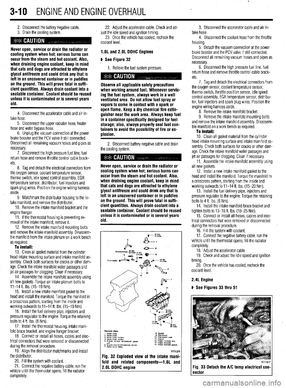
1.6L and 2.OL DDHC Engines
# See Figure 32
1. Relieve the fuel system pressure.
Observe all applicable safety precautions
when working around fuel. Whenever servic-
ing the fuel system, always work in a well
ventilated area. Do not allow fuel spray or
vapors to come in contact with a spark or
open flame. Keep a dry chemical fire extin-
guisher near the work area. Always keep fuel
in a container specifically designed for fuel
storage; also, always properly seal fuel con-
tainers to avoid the possibility of fire or ex-
ulosion.
2. Disconnect battery negative cable and drain
the cooling system.
Never open, service or drain the radiator or
cooling system when hot; serious burns can
occur from the steam and hot coolant. Also,
when draining engine coolant, keep in mind
that cats and dogs are attracted to ethylene
glycol antifreeze and could drink any that is
left in an uncovered container or in puddles
on the ground. This will prove fatal in suffi-
cient quantities. Always drain coolant into a
sealable container. Coolant should be reused
unless it is contaminated or is several years
old.
Fig. 32 Exploded view of the intake mani-
fold and related components-1.6L and
2.OL DDHC engine
3. Disconnect the accelerator cable and air in-
take hose.
4. Disconnect the coolant hose from the throttle
housing.
5. Detach the vacuum connection at the power
brake booster and the PCV valve If still connected.
Disconnect all remaining vacuum hoses and pipes as
necessary.
6. Drsconnect the high pressure fuel line, fuel
return hose and remove throttle control cable brack-
ets
7. Tag and detach the electrical connectors from
the oxygen sensor, coolant temperature sensor,
therm0 switch, throttle position sensor, rdle speed
control assembly, EGR temperature sensor, distribu-
tor, fuel injectors and spark plug wires. Position the
engine wiring harness aside.
8. Remove the intake manifold bracket.
9. Remove the intake mamfold mounting bolts
and remove the intake manifold assembly. Disassem-
ble manifold on a work bench as required.
To install:
10. Clean all gasket material from the cylinder
head intake mounting surface and intake manifold as-
sembly. Check both surfaces for cracks or other dam-
age. Check the intake manifold water passages and
jet air passages for clogging. Clean if necessary.
11. Assemble the Intake manifold assembly using
all new gaskets.
12. Install a new intake manifold gasket to the
head and install the manifold. Torque the manifold in
a crisscross pattern, starting from the inside and
working outwards to 11-14 ft. Ibs. (15-20 Nm).
13. Install the fuel delivery pipe, injectors and
pressure regulator to the engine. Torque the retaining
bolts to 4 ft. Ibs. (6 Nm).
14. Install the intake manifold brace bracket and
tighten bolts to 13-18 ft. Ibs. (18-25 Nm).
15. Connect or install all hoses, cables and elec-
trical connectors that were removed or disconnected
during the removal procedure.
16. Fill the system with coolant.
17. Connect the negative battery cable, run the
vehicle until the thermostat opens, fill the radiator
completely.
18. ‘Adjust the accelerator cable.
19. Check and adjust the idle speed and ignition
timing.
20. Once the vehicle has cooled, recheck the
coolant level.
2.4L Engine
) See Figures 33 thru 51
93153p37 Fig. 33 Detach the A/C temp electrical con- 1