Rear shock MITSUBISHI DIAMANTE 1900 Repair Manual
[x] Cancel search | Manufacturer: MITSUBISHI, Model Year: 1900, Model line: DIAMANTE, Model: MITSUBISHI DIAMANTE 1900Pages: 408, PDF Size: 71.03 MB
Page 296 of 408
WHEELS 8-2
WHEEL ASSEMBLY 8-2
REMOVAL & INSTALLATION 8-2
INSPECTION 8-2
WHEELLUG STUDS 8-2
REMOVAL & INSTALLATION 8-2
FRONT SUSPENSION 8-4
MACPHERSONSTRUTAND COIL
SPRING 8-7
REMOVAL & INSTALLATION 8-7
OVERHAUL 8-7
SHOCKABSORBERAND COIL
SPRING 8-8
REMOVAL &INSTALLATION 8-8
OVERHAUL 8-9
UPPER BALLJOINT 8-9
REMOVAL & INSTALLATION 8-9
INSPECTION 8-9
UPPER CONTROLARM 8-10
REMOVAL &INSTALLATION 8-10
LOWER BALLJOINT 8-10
REMOVAL &INSTALLATION 8-10
INSPECTION 8-10
LOWER CONTROL ARM 8-10
REMOVAL&INSTALLATION 8-10
SWAY BAR 8-12
REMOVAL & INSTALLATION 8-12
KNUCKLE, HUB, AND BEARING 8-13
REMOVAL & INSTALLATION 8-13
WHEEL ALIGNMENT 8-16
CASTER 8-16
CAMBER 8-17
TOE 8-17
REAR SUSPENSION 8-18
STRUT AND COIL SPRING 8-21
REMOVAL & INSTALLATION 8-21
OVERHAUL 8-22
UPPER CONTROLARMS 8-22
REMOVAL & INSTALLATION 8-22
LOWER CONTROL ARMS 8-23
REMOVAL &INSTALLATION 8-23
TRAINING ARM 8-24
REMOVAL & INSTALLATION 8-24
SWAY BAR 8-25
REMOVAL &INSTALLATION 8-25
HUB & BEARINGS 8-25
ADJUSTMENT 8-25
REMOVAL & INSTALLATION 8-25
STEERING 8-27
STEERING WHEEL 8-27
REMOVAL &INSTALLATION 8-27
COMBINATION SWITCH 8-29
REMOVAL &INSTALLATION 8-29
WINDSHIELD WIPER SWITCH 8-29
REMOVAL&INSTALLATION 8-29
IGNITION LOCK CYLINDER 8-29 '
REMOVAL &INSTALLATION 8-29
IGNITION SWITCH 8-30
REMOVAL &INSTALLATION 8-30
STEERING LINKAGE 8-30
REMOVAL&INSTALLATION 8-30
MANUAL RACK AND PINION STEERING
GEAR 8-31 REMOVAL & INSTALLATION 8-31
POWER RACK AND PINION STEERING
GEAR 8-32
REMOVAL &INSTALLATION 8-32
POWERSTEERING PUMP 8-34
REMOVAL &INSTALLATION 8-34
SYSTEM BLEEDING 8-36
COMPONENT LOCATIONS
FRONTSUSPENSION COMPONENT
LOCATIONS 8-4
REARSUSPENSION COMPONENT
LOCATIONS 8-18
SPECIFICATIONS CHARTS ’
TORQUE SPECIFICATIONS 8-39
Page 316 of 408
.
SUSPENSION AND STEERING 8-21
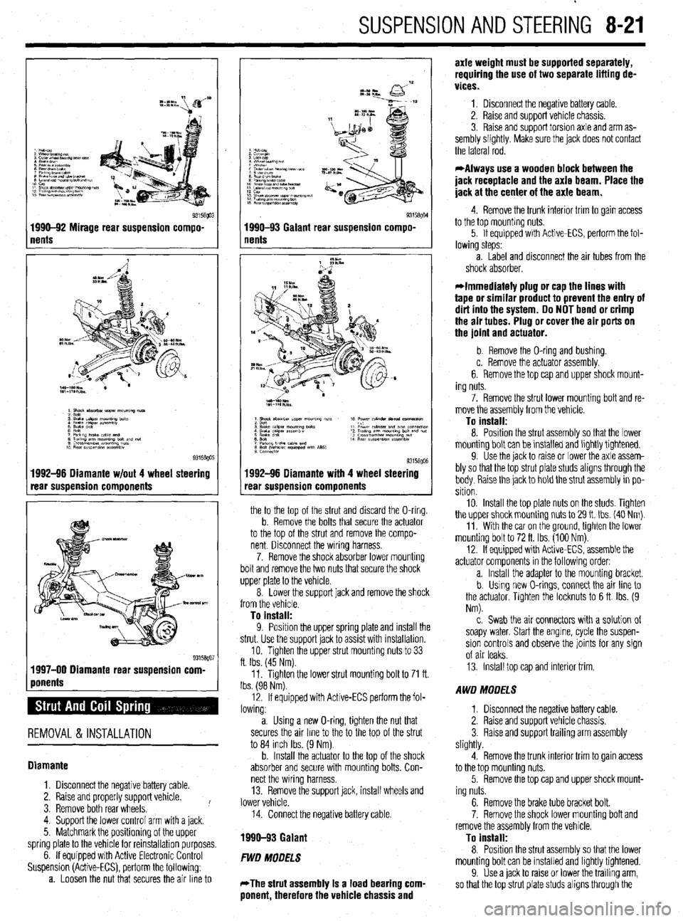
1 nents Q3158!@3 1990-92 Mirage rear suspension compo-
1992-96 Diamante w/out 4 wheel steering
rear suspension components
1 ponents %” 1997-00 Diamante rear suspension corn
REMOVAL & INSTALLATION
Diamante
1. Disconnect the negative battery cable.
2. Raise and properly support vehicle.
3. Remove both rear wheels. !
4. Support the lower control arm with a jack.
5. Matchmark the positioning of the upper
spring plate to the vehicle for reinstallation purposes.
6. If equipped with Active Electronic Control
Suspension (Active-ECS), perform the following:
a. Loosen the nut that secures the air line to
I
93158QM 1990-93 Galant rear suspension compo-
nents
1992-96 Diamante with 4 wheel steering
rear suspension components
the to the top of the strut and discard the O-ring.
b. Remove the bolts that secure the actuator
to the top of the strut and remove the compo-
nent Disconnect the wiring harness.
7. Remove the shock absorber lower mounting
bolt and remove the two nuts that secure the shock
upper plate to the vehicle.
8. Lower the support jack and remove the shock
from the vehicle.
To install:
9. Position the uooer sprina elate and install the
strut. Use the support’jack to as% with installation.
10. Tighten the upper strut mounting nuts to 33
ft. Ibs. (45 Nm).
11. Tighten the lower strut mounting bolt to 71 ft.
Ibs. (98 Nm).
12. If equipped with Active-ECS perform the fol-
lowing:
a. Using a new O-ring, tighten the nut that
secures the air line to the to the top of the strut
to 84 inch Ibs. (9 Nm).
b. Install the actuator to the top of the shock
absorber and secure with mounting bolts. Con-
nect the wiring harness.
13. Remove the support jack, install wheels and
lower vehicle.
14. Connect the negative battery cable.
1990-93 Galant
FWD MODELS
*The strut assembly Is a load bearing com-
ponent, therefore the vehicle chassis and axle weight must be supported separately,
requiring the use of two separate lifting de-
vices.
1. Disconnect the negative battery cable.
2. Raise and support vehicle chassis.
3. Raise and support torsion axle and arm as-
sembly slightly. Make sure the jack does not contact
the lateral rod.
*Always use a wooden block between the
jack receptacle and the axle beam. Place the
jack at the center of the axle beam.
4. Remove the trunk interior trim to gain access
to the top mounting nuts.
5. If equipped with Active-ECS, perform the fol-
lowing steps:
a. Label and disconnect the air tubes from the
shock absorber.
*Immediately plug or cap the lines with
tape or similar product to prevent the entry of
dirt into the system. Do NOT bend or crimp
the air tubes. Plug or cover the air ports on
the joint and actuator.
b. Remove the O-ring and bushing.
c. Remove the actuator assembly.
6. Remove the top cap and upper shock mount-
ing nuts.
7. Remove the strut lower mounting bolt and re-
move the assembly from the vehicle.
To install:
8. Position the strut assembly so that the lower
mounting bolt can be installed and lightly tightened.
9. Use the jack to raise or lower the axle assem-
bly so that the top strut plate studs aligns through the
body. Raise the jack to hold the strut assembly in po-
sition
10. Install the top plate nuts on the studs. Tighten
the upper shock mounting nuts to 29 It. Ibs. (40 Nm).
11. With the car on the ground, tighten the lower
mounting bolt to 72 ft. Ibs. (100 Nm).
12. If equipped with Active-ECS, assemble the
actuator components in the following order:
a. Install the adapter to the mounting bracket.
b. Using new O-rings, connect the air line to
the actuator, Tighten the locknuts to 6 ft Ibs. (9
Nm).
c. Swab the air connectors with a solution of
soapy water. Start the engine, cycle the suspen-
sion controls and observe the joints for any sign
of air leaks.
13. Install top cap and interior trim.
AWD MODELS
1. Disconnect the negative battery cable.
2. Raise and support vehicle chassis.
3. Raise and support trailing arm assembly
slightly.
4. Remove the trunk interior trim to gain access
to the top mounting nuts.
5. Remove the top cap and upper shock mount-
ing nuts.
6. Remove the brake tube bracket bolt.
7. Remove the shock lower mounting bolt and
remove the assembly from the vehicle.
To install:
8. Position the strut assembly so that the lower
mounting bolt can be installed and lightly tightened.
9. Use a jack to raise or lower the trailing arm,
so that the top strut plate studs aligns through the
Page 317 of 408
sembly slightly.
3. In order to gain access to the top mounting
nuts, remove the rear seat as follows:
r
I-- a. While pulling the rear seat stopper out- lb
ward, lift the lower cushion upward. Remove the
lower cushion.
b. Remove the seat back mounting bolts.
c. Lift the seat back upward and remove the
seat.
4. Remove the shock upper mounting nuts.
5. Remove the shock lower mounting bolt and
remove the assembly from the vehicle.
To install:
6. Position the shock assembly so that the
lower mounting bolt can be installed and lightly
tightened.
7. Use a jack to raise or lower the lower control
arm, so that the top shock plate studs align through
the body. Raise the jack to hold the shock assembly
in position.
8 “, In&dl the tnn nlato nl Itc: nn thp dl~rk nnri ,,,“Lu,l .,,” .“* r....” ,.“.., “.. . ..” -.I__-..” tighten the mounting nuts to 32 ft. Ibs. (44 Nm).
9. With the vehicle on the ground, tighten the
lower mounting bolt to 71 ft. Ibs. (98 Nm).
10. Install the rear seat back and cushion.
Miraae
I
1. Remove the trunk interior trim to aain access
to the top mounting nuts.
2. Remove the top cap and upper shock mount-
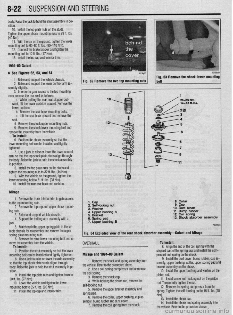
I 1. cap
2 Beif-locking nut
Q* ,A,ll)rrr ii ZPb
10: Dust cbver
11. Bump rubber 12. Coil spring
8-22 SUSPENSION AND STEERING
,
I
ing nuts.
3. Raise andsupport vehicle chassis.
4. Support the trailing arm assembly with a
iack a. ““QJ1vw
;. ~~;~~inp A
6: Spring pad 7. Upper bushing B 13. Shock absorber assembly
I----. 5 Matchmark thF! unner snrino elate to the ve-
I TmFliBl
_. .._._....._... . .._ -TT- _r
u r _.- .-
hicle chassis for reassembly and remove the upper
spring plate mounting nuts.
^ ^
. . .a .I II. I Fig. 64 Exploded view of the rear shock absorber assembly-Galant and Mirage
I
-t
Inrmg DOII ana re-
9.
OVERHAUL To Install:
o A*. .* I b. nemove tne strut lower mol
move the assembly from the vehicle
To install:
7. Position the strut assembly so that the lower
mountino bolt can be installed and liahtlv tiahtened.
8. t&e a jack to raise or lower thk &le&sembly
so that the top shock plate studs aligns through
body. Raise the jack to hold the strut assembly in po-
sition.
9. Install the top plate nuts and tighten them to
20 ft. Ibs. (27 Nm).
mounting bolt to 65 ft. Ibs. (90 Nm).
11. Install the top cap and interior trim. Mirage and 1996-00 Galant 0. ,,ngn me ena of the coil spring with the
stepped part of the spring seat and install the com-
pressed cnil snrinn nn the shock
1. Remove the shock and spring assembly from
the vehicle. Refer to the procedure above.
2. Use a coil spring compressor and compress
the coil spring.
3. Remove the shock cap.
” \w.;,n hrrh~inn +I-.- n;r+nn rnr( rnmn,rc, thn ,. .,,,,,- ,,-,-,* *J ..l” r .I._. * .-_, .-...-.- . ..-
self-locking nut.
5. Remove the upper bracket assembly and
spring pad.
6. Remove the collar, upper bushing, cup as-
sembly, bump rubber and dust cover.
7. Remove the coil spring from the shock. _.. -r,.. J _ _ _ __
9. Install the dust cover, bump rubber, cup as-
sembly, upper bushing, collar, upper spring pad and
bracket assembly on the shock.
10. Install the upper bushing and washer on the
piston rod.
11. Install a new self-locking nut on the piston
roa. temporarily tighten the nut.
12. Remove the spring compressor from the
spring. Tighten the self-locking nut to 16 ft. Ibs. (25
Nm).
13. Install the shock cap.
14. Install the shock and spring assembly into
the v&i&a Rnfnr tn the nmrd~w~ ahnrm
Page 319 of 408
8-24 SUSPENSION AND STEERING
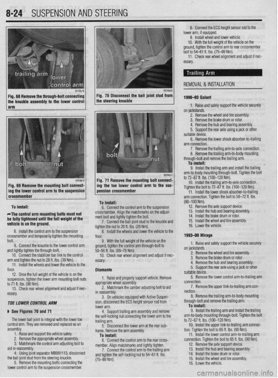
9315t$M 93158p26 Fig. 68 Remove the through-bolt connecting Fig. 70 Disconnect the ball joint stud from
the knuckle assembly to the lower control the steering knuckle
1 arm
Fig. 71 Remove the mounting bolt connect-
Fig, 89 Remove the mounting bolt connect- /
1 ing the toe lower control arm to the SW
Dolt. 9; Connect the knuckle to the lower control arm 9. With the full weigh
ground, tighten the control
and lightly tighten the through-bolt.
10. Connect the stabilizer bar link to the control
arm and tighten the nut to 28 ft. Ibs. (39 Nm).
11. Install the wheels and lower the vehicle to the
floor.
12. Once the full weight of the vehicle is on the
suspension, tighten the lower arm mounting bolt nuts
to 71 ft. Ibs. (98 Nm).
13. Check rear wheel alignment and adjust if nec-
essary.
TOE LOWER CONTROL ARhl
ti See Figures 70 and 71
The lower ball joint is integral with the lower toe
control arm. They are removed and replaced as an
assembly.
1. Raise and support the vehicle safely.
2. Remove the appropriate wheel assembly.
3. Matchmark the control arm adjusting bolt to
aid in reassembly.
4. Using joint separator MB991113, disconnect
the ball joint stud from the steering knuckle.
5. Remove the mounting bolts connecting the
lower control arm to the suspension crossmember. %--56 ft. ibs. (
10. Check
essay. rem an0 aajusr
II nec-
orl vehicle Remove
ldiustina bolt to aid
soen- Diamante
1, Raise and properly supp
appropriate whl
eel assembly.
2. Matchn
narkthe camber a , _
in reassembly.
3. On vehicles equipped with Active Su r
sion, disconnect the ECS height sensor rod from
lower arm.
4. Support trailing arm assembly and remove
the self-locking nut connecting the lower arm to the
trailing arm.
5. Disconnect the lower arm at the rear sub-
frame. Remove the arm assembly.
To install:
6. Connect the control arm to the rear cross-
member. Alion matchmarks and liahtlv tiohten.
7. Connect the control arm tothe trailing arm
and tighten the self-locking nut to 54-P e rho I I IL IY.J.
(75-89 Nm). 8. Connect the ECS height sensor rod to the
lower arm, if equipped.
9. Install wheel and lower vehicle.
IO. With the full weight of the vehicle on the
ground, tighten the control arm to rear crossmember
bolt to 54-61 ft. Ibs. (75-89 Nm).
11,
Check rear wheel alignment and adjust if nec-
essary
1996-93 Galant
1, Raise and safely support the vehicle securely
on jackstands.
2. Remove the wheel and tire assembly.
3. Remove the brake drum or rotor.
4. Remove the hub and bearing assembly.
5.
Support the rear axle using a jack or other
suitable device.
6. Remove the lower shock absorber-to-trailing
arm connection.
7. Remove the trailing arm-to-axle connection.
REMOVAL & INSTALLATION
(80-100 Nm).
12.
Remove the axle suooort device.
on jackstands.
2. Remove the wheel and tire assembly.
3. Remove the brake drum or rotor.
4. Remove the hub and bearing assembly.
5.
Support the rear axle using a jack or other
suitable device.
6. Remove the lower control arm-to-trailing arm
connection.
7. Remove the upper link-to-trailing arm con-
nection.
8. Remove the trailing arm-to-body mounting
through-bolt and remove the trailing arm.
To install:
9.
Install the trailing arm and install the trailing
arm-to-body mounting through-bolt. Tighten the bolt
to 72-87 ft. Ibs. (100-120 Nm).
10. Install the upper link-to-trailing arm connec-
tion. Tighten the bolt to 65 ft. Ibs. (90 Nm).
11. Install the lower control arm-to-trailing arm
connection. Tighten the bolt to 65 ft. Ibs. (90 Nm).
12. Remove the axle support device.
13. Install 1 he hub and bearing assembly.
14 Install 1
. _ .he brake drum or rotor.
15.
Install the wheel and tire assembly.
16. Lower the vehicle.
Page 320 of 408
SUSPENSION AND STEERING 8-25
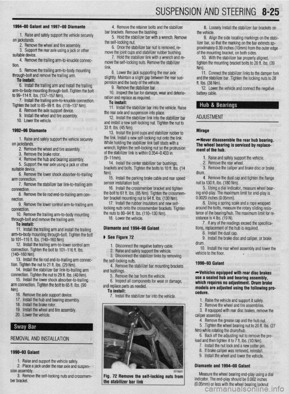
1994-00 Galant and 1997-00 Diamante
4. Remove the retainer bolts and the stabilizer
..- 8, Loosely in”,“,, +I?,, r+&,il;7nr kn- h.~r.l,,d” -..
1. Raise and safely support the vehicle securely he bushing.
the vehicle.
on jackstands.
7er hnr with FI wmnph Remnun (1 Alinn th
2. Remove the wheel and tire assembly.
3. Support the rear axle using a jack or other
suitable device.
4. Remove the trailing arm-to-knuckle connec-
tion,
5. Remove the trailing arm-to-body mounting
n~~““yll-““!~ (1II” fWll”“C LllG llcllllll$j a,,,,. To install:
6. Install the trailing arm and install the trailing
arm-to-body mounting through-bolt. Tighten the bolt
to 99-114 ft. Ibs. (137-157 Nm).
7. Install the trailing arm-to-knuckle connection. Dar brackets. Hemove t
5. Hold the stabilL_. __. . . _ . .._..“... ..I . .._._
the self-locking nut.
6. Once the stabilizer bar nut is removed, re-
move the joint cups and stabilizer rubber bushing.
7. Hold the stabilizer link with a wrench and re-
move the self-locking nuts. Remove the stabilizer
link.
8. Lower the jack supporting the rear axle
in a slight gap between the rear sus-
? body of the vehicle.
! the stabilizer bar.
IL_ L__ I__ _)----- .-- .-J JAI.... slightly. Mainta
pension and thf
9. Remow
10. Inspect LIIB uar 101 uamage, wear ana aereno-
ration and replace as required.
-Fe c--a-...
1 IIIJMII UK 3La”III‘w “ill “lduKm “II
“. , ,,LY,, ,,ie side locating markings on the stabi-
lizer bar, so that the marking on the bar extends ap-
proximately 0.39 inches (1Omm) from the outer edge
of the mounting bracket, on both sides.
10. With the stabilizer bar properly aligned,
tighten the mounting bracket bolts to 28 ft. Ibs. (39
Nm).
11. Connect the stabilizer links to the damper fork
andihe stabilizer bar. Tighten the locking nuts to 28
ft. Ibs. (38 Nm).
12. Lower the vehicle and connect the negative
8.. Ia
mery came.
Tighten the bolt to 85-99 ft. Ibs. (118-137 Nm).
nemove me axle suppon
9. Install the wheel and tire
10. Lower the vehicle. aewce.
assembly.
I 0 Insran: 11, Install the stabilizer bar into the vehicle. Raise
the rear axle and suspension into place.
12. Install the stabilizer link into the stabilizer ba
Ir
ADJUSTMENT anfi indc4ll 33 ft. Ibs. (45 Nm).
13. Install the ioint __-_ _.._ __
1. Raise and safely support the vehicle securely the link. Ins’
..I.,
Mlhiln hnlrii, tall a rkW self~locking n
lll~llG llUlulng the stabi” ” ’ ’ ’
wrench, tighten the self,
of the stabilizer link is v
ihe hub and bearing assembly.
5. Support the rear axle using a jack or other
suitable device.
6. Remove the lower shock absorber-to-trailing
arm connection. ocking nut. Tighten the nut to
ClrnC 2nd ?$bilizer rubber to
ut onto the link.
nzer nnK oall studs with a
-locking nut so the protrusion
within 0.354-0.433 in.
I stabilizer bar bushings,
>+nn thn hnk In -I A u (9-llmm).
14. Install the cente
brackets and bolts. Tiqt Mirage
*Never disassemble the rear hub bearing.
The wheel bearing is serviced by replace-
ment of the hub.
1. Raise and safely support the vehicle.
2. Remove the rear wheel.
3. Remove the caliper and brake disc of brake 1992-96 biamante
on IacKsranos.
2. Remove the wheel and tire assembly
3, Remove thn hralm rntnr 4. Remove1
7. Remove the stabilizer bar link-to-trailing arm
connection.
8. Remove the tie rod end-to-trailing arm con-
nection.
9. Remove the lower control arm-to-trailing arm
connection.
10. Remove the trailing arm-to-body mounting
through-bolt and remove the trailing arm. Nm).
15. Install the parking
sensor installation bolt.
, , I oraxe cat * ale ar
member bracket and tighten
i Nm). Tighten the crossmem-
A to 94 ft. Ibs. (130 Nm). 16. Install the cross
the bolt to 61 ft. Ibs. (8!
ber bracket mounting nl
17. Install the rubbe
locking nuts onto the cro:
the nuts to 80-94 fl. Ibs. (
18. Lower the vehicle. id rear speed drum.
4. Remove the dust cab and tighten the flange ll”, *lb+ to 130 ft. Ibs. (180 Nm).
5. Using a dial indicator, measure wheel bear-
!r insulators and new seif-
ismemoer ’ brackets. Tighten
[110-130 Nm). ing end-play. The maximum limit for end-play is
o.oc-- ‘^ -- rzu mcnes (u.usmm).
arol
tanc
sisk 6. Using a spring scale and a rope wrapped
md the bolts, measure the rotary sliding resis-
e of the bearing/hub. The maximum limit for re-
mce is 4 Ibs. (19 N).
7. If any of the readings exceed the specifica-
To install:
11. Install the trailing arm and install the trailina Diamante and 1994-98 Gal&i
t tions, replacement of the hub is required.
8. Install the dust cap.
9. Install the brake disc and caliper, or brake
negative battery ( sble.
;“I,-.
I support the vbhlblG.
stabilizer links by removing
Alizer bar mounting brackets
from the vehicle.
lonents for wear or damage,
ded. drum.
10. Install the rear wheel assembly and lower the
vehicle to the floor.
*
1990-93 Galant
*Vehicles equipped with rear disc brakes
use a sealed hub and bearing assembly,
which requires no adjustment. Drum brake
models are
adjusted using the following pro- arm-to-body mounting through-bolt. Tighten the bolt
to 101-116 ft. Ibs. (140-160 Nm). ) See Figure 72
12. Install the trailing arm-to-lower control arm
1. Disconnect the I
connection. Tighten the bolt to 101-116 ft. Ibs.
(140-160 Nm). 2. Raise and safely
13. Install the tie rod end-to-trailing arm connec- 3. Disconnect the I
tion. Tighten the nut to 21 ft. Ibs. (29 Nm). the self-locking nuts.
14. Install the stabilizer bar link-to-trailing arm 4. Remove the stat
connection. Tighten the nut to 29 ft. Ibs. (40 Nm). and bushings.
15. Install the lower shock absorber-to-trailing
5. Remove the bar
arm connection. Tighten the bolt to 65 ft. Ibs. (90 6. Inspect all comr
. and replace parts as nee
Nrn).
16. Remove the axle support device.
17. Install the hub and bkaring assembly,
18. Install the brake rotor.
19. Install the wheel and tire assembly.
20. Lower the vehicle.
REMOVALANDINSTALLATION
1990-93 Gaiant
1. Raise and support the vehicle safely.
2. Place a jack under the rear axle and suspen- To install:
7 InstA the dnhili cedure. ._._ . . .._ -.--.. lzer bar into the vehicle.
1. Raise the vehicle and support it safely.
2. Remove the wheel and tire assemblies.
3. If equipped with rear disc brakes, remove the
caliper assembly.
4. Remove the grease cap and the hub nut.
5. Tighten the wheel bearing nut to 20 ft. Ibs. (27
Nm) while rotatir ” ”
6. Back off th
load and then tighten it to 7 ft. Ibs. (10 Nm).
7. Install the nut lock and a new cotter pin.
8. If brake caliper was removed, reinstall.
9. Install the wheel and lower the vehicle.
Diamante and lQQ44 Galant 10 tne mum/hub.
ie adjusting nut to remove the pre-
Sian assembly.
3. Remove the self-locking nuts and crossmem-
ber bracket.
93158P61 Fig. 72 Remove the self-locking nuts from Measure the wheel bearing end-play using a dial
the stabilizer bar link indicator. The end-play should be 0.002 inches
a (0.05mm) or less with the wheel bearing locknut
Page 321 of 408
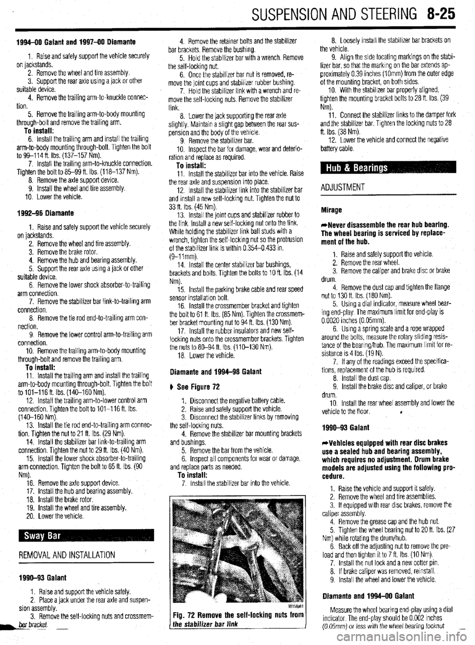
SUSPENSION AND STEERING 8-25
1994-00 Galant and 1997-00 Diamante
1, Raise and safely support the vehicle securely
on jackstands.
2. Remove the wheel and tire assembly.
3. Support the rear axle using a jack or other
suitable device.
4. Remove the trailing arm-to-knuckle connec-
tion.
5. Remove the trailing arm-to-body mounting
through-bolt and remove the trailing arm.
To install: 6. Install the trailing arm and install the trailing
arm-to-body mounting through-bolt. Tighten the bolt
to 99-114 ft. lbs. (137-157 Nm).
7. Install the trailing arm-to-knuckle connection.
Tighten the bolt to 85-99 ft. Ibs. (118-137 Nm).
8. Remove the axle support device.
9. install the wheel and tire assembly.
10. Lower the vehicle.
1992-96 Diamante
1. Raise and safely support the vehicle securely
on jackstands.
2. Remove the wheel and tire assembly.
3. Remove the brake rotor.
4. Remove the hub and bearing assembly.
5. Support the rear axle using a jack or other
suitable device.
6. Remove the lower shock absorber-to-trailing
arm connection.
7. Remove the stabilizer bar link-to-trailing arm
connection.
8. Remove the tie rod end-to-trailing arm con-
nection.
9. Remove the lower control arm-to-trailing arm
connection.
10. Remove the trailing arm-to-body mounting
through-bolt and remove the trailing arm.
To install: 11, Install the trailing arm and install the trailing
arm-to-body mounting through-bolt. Tighten the bolt
to lOl-116ft. Ibs. (14C-160 Nm).
12. Install the trailing arm-to-lower control arm
connection. Tighten the bolt to 101-116 ft. Ibs.
(140-l 60 Nm).
13. Install the tie rod end-to-trailing arm connec-
tion. Tighten the nut to 21 ft. Ibs. (29 Nm).
14. Install the stabilizer bar link-to-trailina arm
connection. Tighten the nut to 29 ft. Ibs. (40 im).
15. Install the lower shock absorber-to-trailing
arm connection. Tighten the bolt to 65 ft. Ibs. (90
Nm).
16. Remove the axle support device.
17. Install the hub and bearing assembly.
18. Install the brake rotor.
19. Install the wheel and tire assembly.
20. Lower the vehicle.
REMOVALANDINSTALLATION '
1990-93 Galant
1. Raise and support the vehicle safely.
2. Place a jack under the rear axle and suspen-
sion assembly.
3. Remove the self-locking nuts and crossmem-
her bracket.
d.--- -.
Fig. 72 Remove the self-locking nuts from
the stabilizer bar link 8. Loosely install the stabilizer bar brackets on
the vehicle.
9. Align the side locating markings on the stabi-
lizer bar, so that the marking on the bar extends ap-
proximately 0.39 inches (1Omm) from the outer edge
of the mounting bracket, on both sides.
10. With the stabilizer bar properly aligned,
tighten the mounting bracket bolts to 28 ft. Ibs. (39
Nm).
11. Connect the stabilizer links to the damper fork
andjhe stabilizer bar. Tighten the locking nuts to 28
ft. Ibs. (38 Nm).
12. Lower the vehicle and connect the negative
battery cable.
ADJUSTMENT
1990-93 Galant
*Vehicles equipped with rear disc brakes
use a sealed hub and bearing assembly,
which requires no adjustment. Drum brake
models are adjusted using the following pro-
cedure.
1. Raise the vehicle and support it safely.
2. Remove the wheel and tire assemblies.
3. If equipped with rear disc brakes, remove the
caliper assembly.
4. Remove the grease cap and the hub nut.
5. Tighten the wheel bearing nut to 20 ft. Ibs. (27
Nm) while rotating the drum/hub.
6. Back off the adjusting nut to remove the pre-
load and then tighten it to 7 ft. Ibs. (10 Nm).
7. Install the nut lock and a new cotter pin.
8. If brake caliper was removed, reinstall.
9. Install the wheel and lower the vehicle.
Diamante and 1994-00 Galant
Measure the wheel bearing end-play using a dial
indicator. The end-play should be 0.002 inches
(0.05mm) or less with the wheel bearing locknut _
Page 329 of 408
SUSPENSION AND STEERING 8-33
*Matchmark the pinion input shaft of the
rack to the lower steering column joint for in-
stallation purposes.
6. Remove the pinch bolt holding the lower
steering column joint to the rack and pinion input
shaft.
7. Remove the cotter pins and disconnect the tie
rod ends from the steering knuckle.
8. Remove the rack and pinion steering assem-
bly and its rubber mounts from the right side of the
vehicle.
To install: 9. Align the matchmarks of the input shaft and
install the rack to the vehicle.
10. Secure the rack using the retainer clamps and
bolts. Tighten the bolts to 51 ft. Ibs. (70 Nm).
11. Tighten the steering column pinch bolt to 13
ft. Ibs. (18 Nm).
12. Install the center member.
13. Install the front exhaust pipe.
14. Connect the HO$ sensor.
15. Connect the tie rod ends to the steering
knuckles and tighten the castle nuts to 25 ft. Ibs. (34
Nm). Install new cotter pins.
16. Install the wheels and connect the negative
battery cable.
17. Have a front end alignment performed.
REMOVAL &INSTALLATION
Diamante
FRONT
*Prior to removal of the steering gear box,
center the front wheels and remove the igni-
tion key. Failure to do so may damage the
SRS clock spring and render SRS system in-
operative.
1. Disconnect the negative battery cable.
2. Disconnect the front exhaust pipe.
3. If equipped with AWD, remove the transfer
case assembly.
4. Remove the bolt holding the lower steering
column joint to the rack and pinion input shaft.
5. Remove the cotter pins and disconnect the tie
rod ends.
6. Remove the left and right frame members.
7. Remove the stabilizer bar bracket.
8. If equipped with four-wheel steering, discon-
nect the lines going to the rear pump.
9. Remove the rack and pinion steering assem-
bly and its rubber mounts. Move the rack to the right
to remove it from the crossmember.
To install: IO. Install the rack and mounting bolts. Tighten
the bolts to 51 ft. Ibs. (70 Nm). When installing the
rubber rack mounts, align the projection of the
mounting rubber with the indentation in the cross:
member. Install the pinch bolt.
11. Connect the pressure and return lines to the
rack and to the rear pump, if equipped.
12. Install the frame members and tighten the
bolts to 43-51 ft. Ibs. (60-70 Nm).
13. Connect the tie rods and install new cotter
pins. 14. Install the transfer case and front exhaust
pipe.
15. Refill the reservoir and bleed the system.
16. Have a front end alignment performed.
REAR
1. Disconnect the negative battery cable.
2. Raise the vehicle and support safely.
3. Drain the power steering fluid.
4. Remove the main muffler assembly.
5. Remove the rear shock absorber lower
mounting bolts.
6. Using the proper equipment, support the
weight of the rear differential. Remove the 2 small
crossmember brackets.
7. Remove the large self-locking crossmember
mounting nuts on the differential side.
8. Remove the oil line clamp bolts.
9. Remove the pressure tubes.
IO. Hold the tie rod ends stationary and remove
the tie rod end nuts. Remove the tie rod ends from
the trailing arms.
11. Remove the mounting bolts and remove the
rear steering gear.
To install: 12. Secure the unit to the crossmember. Move
the power cylinder piston rod over its full stroke to
determine its neutral position.
13. Align the tie rod ends with the holes in the
trailing arms and install the nuts. Adjust the length of
the tie rods with the nuts if necessary. The difference
in length between the 2 tie rod ends should not ex-
ceed 0.04 in. (1 mm). The nuts’ torque specification is
42 ft. Ibs. (58 Nm).
14. Replace the O-rings and install the pressure
tubes. Clamp in place.
15. Install the large self-locking crossmember
mounting nuts on the differential side. Tighten to
80-94 ft. Ibs. (110-130 Nm).
16. Remove the support equipment.
17. Install the 2 small crossmember brackets.
18. Install the shock mounting bolts.
19. Install the muffler assembly.
20. Refill the reservoir and bleed the system.
21. Have a front end alignment performed. _
Galant
1990-93 MODELS
1. Disconnect the negative battery cable.
2. Drain the power steering fluid.
3. Raise the vehicle and support safely.
4. Remove the bolt holding lower steering col-
umn joint to the rack and pinion input shaft.
5. Remove the transfer case, if equipped.
6. Remove the cotter pins and using the proper
tools, separate the tie rod ends from the steering
knuckle.
7. Locate the triangular brace near the stabilizer
bar brackets on the crossmember and remove both
the brace and the stabilizer bar bracket.
8. Support the center crossmember.
9. Remove the through-bolt from the round roll
stopper and remove the rear bolts from the center
crossmember.
10. Disconnect the front exhaust pipe, if
equipped with FWD.
11. Disconnect the power steering fluid pressure
pipe and return hose from the rack fittings. Plug the
fittings to prevent excess fluid leakage. 12. Lower the crossmember slightly.
13. Remove the rack and pinion steering assem-
bly and its rubber mounts. Move the rack to the right
to remove from the crossmember. Tilt the assembly
downward and remove from the left side of the vehi-
cle. Use caution to avoid damaging the boots.
To install: 14. Install the rack and install the mounting bolts. Tighten the mounting bolts to 43-58 ft. Ibs. (60-80
Nm). When installing the rubber rack mounts, align
the projection of the mounting rubber with the inden-
tation in the crossmember.
15. Connect the power steering fluid lines to the
rack.
16. Connect the exhaust pipe, if removed.
17. Raise the crossmember into position. Install
the center member mounting bolts and tighten to 72
ft. Ibs. (100 Nm). Install the roll stopper bolt and new
nut. Tighten nut to 47 ft. Ibs. (65 Nm).
18. Install the stabilizer bar brackets and brace.
19. Connect the tie rod ends and tighten nuts to
25 ft. Ibs. (34 Nm).
20. Install the transfer case, if removed. Check
and fill fluid.
21. Refill the reservoir with power steering fluid
and bleed the system.
22. Have a front end alignment performed.
1994-M MODELS
+ See Figure 96
Prior to removal of the steering gear box,
center the front wheels and remove the igni-
tion key. Failure to do so may damage the
SRS clock spring and render SRS system in-
operative.
1. Disconnect the negative battery cable.
2. Raise and properly support the vehicle.
3. Remove both front wheel assemblies.
4. Remove the bolt holding lower steering col-
umn joint to the rack and pinion input shaft.
5. Remove the stabilizer bar.
6. Remove the cotter pins, and using joint sepa-
rator MB991 113 or equivalent, disconnect the tie rod
ends from the steering knuckle.
7. On vehicles equipped with Electronic Control
Power steering (EPS), detach the wiring harness from
the solenoid connector.
8. Locate the two triangular braces near the
crossmember and remove both.
9. Support the center crossmember. Remove the
through-bolt from the front round roll stopper and re-
move the bolts securing the center crossmember.
10. Remove the center crossmember. ,
Il. Properly support the engine and remove the
rear roll stopper through-bolt.
12. Disconnect the power steering fluid pressure
pipe and return hose from the rack fittings. Plug the
fittings to prevent excessive fluid leakage.
13. Remove the clamp bolts and the two bolts se-
curing the rack assembly to the chassis.
14. Remove the rack and pinion steering assem-
bly and its rubber mounts.
*When removing the rack and pinion as-
sembly, tilt the assembly to the vehicle side
of the compression lower arm and remove
from the left side of the vehicle.
Page 335 of 408
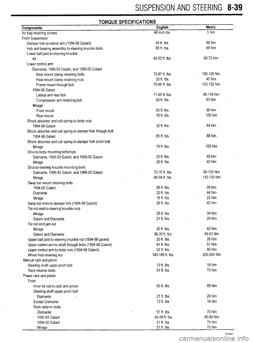
SUSPENSION AND STEERliG 8-39
Components
Air bag retaining screws TORQUE SPECIFICATIONS English
48 inch Ibs. Metric
5Nm
Front Suspension
Damper fork-to-lateral arm (1994-98 Galant)
Hub and bearing assembly-to-steering knuckle bolts
Lower ball joint-to-steering knuckle
I
All
Lower control arm
Diamante, 1990-93 Galant, and 1999-00 Galant
Rear mount clamp retaining bolts
Rear mount clamp retaining nuts
Frame mount through bolt
1994-98 Galant
Lateral arm rear bolt
Compression arm retaining bolt
Mirage
Front mount
Rear mount
Shock absorber and coil spring-to-body nuts
1994-98 Galant
Shock absorber and coil spring-to-damper fork through bolt
1994-98 Galant
Shock absorber and coil spring-to-damper fork pinch bolt
Mirage
Strut-to-body mounting bolts/nuts
Diamante, 1990-93 Galant, and 1999-00 Galant
Mirage
Strut-to-steering knuckle mounting bolts
Diamante, 1990-93 Galant, and 1999-00 Galant
Mirage
Sway bar mount retaining bolts
1994-00 Galant
Diamante
Mirage
Sway bar links-to-damper fork (1994-98 Galant)
Tie-rod end-to-steering knuckle nuts
Mirage
Galant and Diamante
Tie rod end jam nut
Mirage
. Galant and Diamante
Upper ball joint-to-steering knuckle nut (1994-98 galant)
Upper control arm-to-shaft through bolts (1994-98 Galant)
Upper control arm-to-body nuts (1994-98 Galant)
Wheel hub retaining nut
Manual rack and pinion
Steering shaft upper pinch bolt
Rack retainer bolts
Power rack and pinion
Front
Inner tie rod-to-rack and pinion
Steering shaft upper pinch bolt
Diamante I
Except Diamante
Rack retainer bolts
Diamante
1990-93 Galant
1994-00 Galant . 64 ft. Ibs.
65 ft. Ibs.
43-52 ft. Ibs.
72-87 ft. Ibs.
29 ft. Ibs.
75-90 ft. Ibs.
71-85 ft Ibs.
60 ft. Ibs.
65 ft. tbs.
78 ft. Ibs.
32 ft. Ibs.
65 ft. Ibs.
76 ft. Ibs.
33
ft. tbs. 29 ft. Ibs.
70-76 ft. Ibs.
80-94 ft. Ibs.
28 ft. Ibs.
32 ft. Ibs.
16 ft. Ibs.
29 ft. Ibs
25 ft. Ibs.
21 ft. Ibs.
30 ft. tbs.
36-39 ft. Ibs.
20 ft. Ibs.
41 ft. Ibs.
62 ft. Ibs.
145-188 ft. Ibs.
13 ft. Ibs.
51 ft. lbs.
65 ft. Ibs.
21 fta Ibs.
13 ft. Ibs.
51 ft. Ibs.
43-58 ft. Ibs
51 ft. Ibs. 88 Nm
88 Nm
60-72 Nm
100-120 Nm
40 Nm
102-l 22 Nm
98-l 18 Nm
83 Nm
90Nm
108 Nm
44 Nm
88 Nm
103 Nm
45 Nm
40 Nm
90-105 Nm
110-130 Nm
39 Nm
44 Nm
22 Nm
40 Nm
34 Nm
29 Nm
42 Nm
49-53 Nm
28 Nm
57 Nm
86 Nm
200-260 Nm
18Nm
70 Nm
88 Nm
29 Nm
l8Nm
70Nm -
60-80 Nm
70 Nm
70 Nm
93158cOl
Mirage 51 ft. Ibs.
Page 356 of 408
‘I
9-20 ,BRAKES
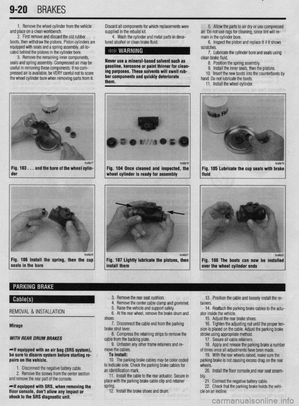
1. Remove the wheel cylinder from the vehicle
and place on a clean workbench.
2. First remove and discard the old rubber
boots, then withdraw the pistons. Piston cylinders are
equipped with seals and a spring assembly, all lo-
cated behind the pistons in the cylinder bore.
3. Remove the remaining inner components,
seals and spring assembly. Compressed air may be
useful in removing these components. If no com-
pressed air is available, be VERY careful not to score
the wheel cylinder bore when removing parts from it. Discard all components for which replacements were
supplied in the rebuild kit.
4. Wash the cylinder and metal parts in dena-
tured alcohol or clean brake fluid.
Never use a mineral-based solvent such as
gasoline, kerosene or paint thinner for clean-
ing purposes. These solvents will swell rub-
ber components and quickly deteriorate
them. 5. Allow the parts to air dry or use compressed
air. Do not use rags for cleaning, since lint will re-
main in the cylinder bore.
6. Inspect the piston and replace it if it shows
scratches.
7. Lubricate the cylinder bore and seals using
- clean brake fluid.
8. Position the spring assembly.
9. Install the inner seals, then the pistons.
IO. Insert the new boots into the counterbores bv
hand. Do not lubricate the boots,
11, Install the wheel cylinder,
m9017 Fig. 103. . .
and the bore of the wheel cylin- der
-9P20 Fig. 106 Install the spring, then the cup
seals in the bore 1 Fig. 104 Once cleaned and inspected, the
1 wheel cylinder Is ready for assembly
1 install them Fig 107 Lightly lubricate the pistons z
’ Fig. 108 The boots can now be instaT:
over the wheel cylinder ends
REMOVAL& INSTALLATION
Mirage
WITH REAR DRUM BRAKES
-If equipped witti an air bag (SRS system), 3. Remove the rear seat cushion.
13. Position the cable and loosely install the re-
4. Remove the center cable clamp and grommet.
tainers.
5. Raise the vehicle and support safely.
14. Reattach the parking brake cables to the actu-
6. At the rear wheel, remove the brake drum and
ator inside the vehicle.
shoes.
15. Adjust the rear brake shoes.
7. Disconnect the cable end from the parking
16. Tighten the adjusting nut until the proper ten-
brake strut lever.
sion is placed on the cable. Adjust the parking brake
8. Compress the retaining strips to remove the
stroke using appropriate method.
cable from the backing plate.
17. Secure all cable retainers,
9. Unfasten any other frame retainers and re-
18. Apply and release the parking brake a number
move the cables.
of times once all adjustments have been made.
be sure to disarm system
befok starting rd-
aairs on the vehicle. To install:
10. The parkinq brake cables mav be color coded 19. With the rear wheels raised, make sure the
oarkino brake is not causina excess draa on the rear
1. Disconnect the negative battery cable.
2. Remove the screws from the center section
and remove the rear part of the console.
*If equipped with SRS, when removing the
floor console,
don’t allow any impact or
shock to the SRS diagnostic unit. to indicate stde. Check the parking brake cables for
wheels: .A
an identification mark.
20. Install the floor consoleand rear seat assem-
11. Install the cable to the rear actuator. Secure in
bly.
place with the parking brake cable clip and retainer
21. Connect the negative battery cable.
spring.
22. Check that the parking brake holds the vehi-
12. Install the brake shoes and drum.
cle on an incline.
Page 357 of 408
BRAKES 9-21
WITH REAR DISC BRAKES
*If equipped with an air bag (SRS system),
be sure to disarm the system before starting
repairs on the vehicle.
1. Disconnect the negative battery cable.
2. Remove the screws from the center section
and remove the rear part of the console.
*If equipped with SRS, when removing the
floor console, don’t allow any impact or
shock to the SRS diagnostic unit.
3. Remove the rear seat cushion.
4. Loosen the cable adjusting nut and discon-
nect the rear brake cables from the actuator.
5. Remove the center cable clamp and grommet.
6. Raise the vehicle and support safely.
7. Remove the parking brake cable clip and re-
tainer spring.
8. Disconnect the cable end from the parking
brake assembly.
9. Unfasten any remaining frame retainers and
remove the cables from the vehicle.
To install: IO. The parking brake cables may be color coded
to indicate side. Check the parking brake cables for
an identification mark.
11. Install the cable to the rear actuator. Secure in
place with the parking brake cable clip and retainer
spring.
12. Position the cable and loosely install the re-
tainers.
13. Reattach the parking brake cables to the actu-
ator inside the vehicle.
14. Tighten the adjusting nut until the proper ten-
sion is placed on the cable. Adjust the parking brake
. stroke using appropriate method.
15. Secure all cable retainers.
16. Apply and release the parking brake a number
of times once all adjustments have been made.
17. With the rear wheels raised, make sure the
parking brake is not causing excess drag on the rear
wheels.
18. Install the floor console and rear seat assem-
bly.
19. Connect the negative battery cable.
20. Check console electrical components for
proper operation.
21. Road test the vehicle and check for proper
brake operation.
22. Check that the parking brake holds the vehi-
cle on an incline.
1990-93 Galant
WITH REAR DRUM BRAKES
1. Disconnect the negative battery cable.
2. Remove the center console as follows:
a. Remove both side cover panels.
b. Remove the shifter knob on manual
transaxle models. Remove the spacer trim piece
on automatic transaxle models.
c. Remove the switch panel/box and remove
the two screws beneath the panel/box.
d. Remove the radio trim panel.
e. Remove the radio and tape player.
f. Remove the console inner panel and re-
move the two screws for beneath the panel.
g. Remove the remaining screws from the
sides of the console. h. Remove the console assembly from the ve-
hicle.
3. While pressing downward on the front of the
rear seat cushion, release the locking levers and re-
move the seat cushion.
4. Loosen the cable adjustment at the cable
equalizer.
5. Remove the center cable clamp and grommet.
6. Raise the vehicle and support safely.
7. At the rear wheel, remove the brake drum and
shoes.
8. Disconnect the cable end from the parking
brake strut lever.
9. Remove the snapring securing the cable to
the backing plate.
IO. Unfasten any other frame retainers and re-
move the cables.
To install:
*The parking brake cables may be color
coded to indicate side. Check the parking
brake cables for an identification mark.
11. Install the cable to the rear actuator. Secure in
place with the parking brake cable clip and snapring.
12. Install the brake shoes and drum.
13. Position the cable and loosely install the re-
tainers
14. Reattach the parking brake cables to the actu-
ator inside the vehicle. Tighten the adjusting nut until
the proper tension is placed on the cable. Adjust the
parking brake stroke using appropriate method.
15. Secure all cable retainers.
16. Apply and release the parking brake a number
of times once all adjustments have been made.
17. Adjust the rear brakes and parking brake ca-
bles.
18. Check the rear wheels to confirm that the rear
brakes are not dragging.
19. Install the center console and rear seat cush-
ion.
20. Connect the negative battery cable.
21. Check console electrical components for
proper operation.
22. Check that the parking brake holds the vehi-
cle on an incline.
WITH REAR DISC BRAKES
1. Disconnect the negative battery cable.
2. Remove the center console as follows:
a. Remove both side cover panels.
b. Remove the shifter knob on manual
transaxle models. Remove the spacer trim piece
on automatic transaxle models.
c. Remove the switch panel/box and remove
the two screws beneath the panel/box.
d. Remove the radio trim panel.
e. Remove the radio and tape player.
f. Remove the console inner panel and re-
move the two screws from beneath the panel.
g. Remove the remaining screws from the
sides of the console.
h. Remove the console assembly from the ve-
hicle.
3. While pressing downward on the front of the
rear seat cushion, release the locking levers and re-
move the seat cushion.
4. Loosen the cable adjusting nut and discon-
nect the rear brake cables from the actuator.
5. Remove the center cable clamp and grommet.
6. Raise the vehicle and support it safely. 7. At the rear caliper assembly, remove the
parking brake cable clip and retainer spring.
8. Disconnect the cable end from the caliper.
9. Unfasten any remaining frame retainers and
remove the cables from the vehicle.
To install:
*The parking brake cables may be color
coded to indicate side. Check the parking
brake cables for an identification mark.
IO. Connect the cable to the actuator at the brake
caliper. Secure in place with the parking brake cable
clip and retainer spring.
11. Position the cable and loosely install the re-
tainers.
12. Reattach the parking brake cables to the actu-
ator inside the vehicle. Tighten the adjusting nut until
the proper tension is placed on the cable.
13. Adjust the parking brake stroke using appro-
priate method.
14. Secure all cable retainers.
15. Apply and release the parking brake a number
of times once all adjustments have been made.
16. With the rear wheels raised, make sure the
parking brake is not causing excess drag on the rear
wheels.
17. Install the floor console assembly and rear
seat cushion.
18. Connect the negative battery cable.
19. Check console electrical components for
proper operation.
20. Road test the vehicle and check for proper
brake operation.
21. Check that the parking brake holds the vehi-
cle on an incline.
1994-00 Galant
WITH REAR DRUM BRAKES
1. Disconnect the negative battery cable.
The SRS control unit is mounted beneath the
center console. Use care when working with
the center console assembly not to impact or
shock the control unit.
2. Remove the center floor console assembly as
follows:
a. Remove the shifter knob on models
equipped with a manual transaxle.
b. Remove the shifter trim panel.
c. Remove the center instrument panel.
d. Remove the panel box from the console
assembly.
e. Remove the two screws from the center of
the console.
f. Remove the four side panel screws and re-
move the console from the vehicle.
3. Loosen the cable adjuster nut, then remove
the parking brake cable by pulling it from the passen-
ger compartment.
4. Raise the vehicle and support safely.
5. At the rear wheel, remove the brake drum and
shoes.
6. Disconnect the cable end from the parking
brake strut lever. Compress the retaining strips to re-
move the cable from the backing plate.