set clock MITSUBISHI DIAMANTE 1900 Repair Manual
[x] Cancel search | Manufacturer: MITSUBISHI, Model Year: 1900, Model line: DIAMANTE, Model: MITSUBISHI DIAMANTE 1900Pages: 408, PDF Size: 71.03 MB
Page 2 of 408
.
1-2 GENERALINFORMATIONAND MAINTENANCE
Chitton’s Total Car Care manual for the 199M10
Mitsubishi Mirage, Galant and Diamante is intended
to help you learn more about the inner workings of
your vehicle while saving you money on its upkeep
and operation.
The beginning of the book will likely be referred to
the most, since that is where you will find information
for maintenance and tune-up. The other sections deal
with the more complex systems of your vehicle. Oper-
ating systems from engine through brakes are cov-
ered to the extent that the average do-it-yourselfer be-
comes mechanically involved. This book will not
explain such things as rebuilding a differential for the
simple reason that the expertise required and the in-
vestment in special tools make this task uneconomi-
cal. It will, however, give you detailed instructions to
help you change your own brake pads and shoes, re-
place spark plugs, and perform many more jobs that
can save you money, give you personal satisfaction
and help you avoid expensive problems.
A secondary purpose of this book is a reference for
owners who want to understand their vehicle and/or
their mechanics better. In this case, no tools at all are
required.
Before removing any bolts, read through the entire
procedure. This will give you the overall view of what
tools and supplies will be required. There is nothing
more frustrating than having to walk to the bus stop
on Monday morning because you were short one bolt
on Sunday afternoon. So read ahead and plan ahead.
Each operation should be approached logically and
all procedures thoroughly understood before attempt-
ing any work.
All sections contain adjustments, maintenance, re-
moval and installation procedures, and in some cases,
repair or overhaul procedures. When repair is not con-
sidered practical, we tell you how to remove the part
and then how to install the new or rebuilt replacement.
In this way, you at least save labor costs. “Backyard”
repair of some components is just not practical.
Many procedures in this book require you to “label
and disconnect. . ” a group of lines, hoses or wires.
Don’t be lulled into thinking you can remember where
everything goes-you won’t. If you hook up vacuum
or fuel lines incorrectly, the vehicle may run poorly, if
at all. If you hook up electrical wiring incorrectly, you
may instantly learn a very expensive lesson.
You don’t need to know the official or engineering
name for each hose or line. A piece of masking tape
on the hose and a piece on its fitting will allow you to
assign your own label such as the letter A or a short name. As long as you remember your own code, the
lines can be reconnected by matching similar letters
or names. Do remember that tape will dissolve in
gasolrne or other fluids; if a component is to be
washed or cleaned, use another method of identifica-
tion. A permanent felt-tipped marker or a metal scribe
can be very handy for marking metal parts. Remove
any tape or paper labels after assembly.
It’s necessary to mention the difference between
maintenance and repair Maintenance includes rou-
tine inspections, adjustments, and replacement of
parts which show signs of normal wear Maintenance
compensates for wear or deterioration. Repair implies
that something has broken or is not working. A need
for repair is often caused by lack of maintenance. Ex-
ample, draining and refilling the automatic transaxle
fluid is maintenance recommended by the manufac-
turer at specific mileage intervals. Failure to do this
can shorten the life of the transmission/transaxle, re-
quiring very expensive repairs. While no maintenance
program can prevent items from breaking or wearing
out, a general rule can be stated: MAINTENANCE IS
CHEAPER THAN REPAIR.
Two basic mechanrc’s rules should be mentioned
here. First, whenever the left side of the vehicle or en-
gine is referred to, it is meant to specify the drivers
side. Conversely, the right side of the vehicle means
the passengers side. Second, screws and bolts are
removed by turning counterclockwise, and tightened
by turning clockwrse unless specifically noted.
Safety is always the most important rule. Con-
stantly be aware of the dangers involved in working
on an automobile and take the proper precautions.
See the informatron in this section regarding SER-
VICING YOUR VEHICLE SAFELY and the SAFETY
NOTICE on the acknowledgment page.
Pay attention to the instructions provided. There
are 3 common mistakes in mechanical work:
1. Incorrect order of assembly, disassembly or
adjustment. When taking something apart or putting
it together, performing steps in the wrong order usu-
ally just costs you extra time; however, it CAN break
something. Read the entire procedure before begin-
ning disassembly. Perform everything in the order in
which the instructions say you should, even if you
can’t immedrately see a reason for it. When you’re
taking apart something that is very intricate, you
might want to draw a picture of how it looks when as-
sembled at one point in order to make sure you get everything back in its proper position. We will supply
exploded views whenever possible. When making
adjustments, perform them in the proper order. One
adjustment possibly will affect another.
2. Overtorquing (or undertorquing). While it is
more common for overtorquing to cause damage,
undertorquing may allow a fastener to vibrate loose
causing serious damage. Especially when dealing
with aluminum parts, pay attention to torque specifi-
cations and utilize a torque wrench in assembly. If a
torque figure is not available, remember that if you
are using the right tool to perform the job, you will
probably not have to strain yourself to get a fastener
tight enough. The pitch of most threads is so slight
that the tension you put on the wrench will be multi-
plied many times in actual force on what you are
tightening. A good example of how critical torque is
can be seen in the case of spark plug installation, es-
pecially where you are putting the plug into an alu-
minum cylinder head. Too little torque can fail to
crush the gasket, causing leakage of combustion
gases and consequent overheating of the plug and
engine parts. Too much torque can damage the
threads or distort the plug, changing the spark gap.
There are many commercial products available for
ensuring that fasteners won’t come loose, even if they
are not torqued just right (a very common brand is
Loctite? If you’re worried
about getting something
together tight enough to hold, but loose enough to
avoid mechanical damage during assembly, one of
these products might offer substantial insurance. Be-
fore choosing a threadlocking compound, read the
label on the package and make sure the product is
compatible with the materials, fluids, etc. involved.
3. Crossthreading. This occurs when a part such
as a bolt is screwed into a nut or casting at the wrong
angle and forced. Crossthreading is more likely to
occur if access is difficult. It helps to clean and lubri-
cate fasteners, then to start threading the bolt, spark
plug, etc. with your fingers If you encounter resis-
tance, unscrew the part and start over again at a dif-
ferent angle until it can be inserted and turned several
times without much effort. Keep in mind that many
parts, especially spark plugs, have tapered threads,
so that gentle turning will automatically bring the part
you’re threading to the proper angle. Don’t put a
wrench on the part until its been tightened a couple
of turns by hand. If you suddenly encounter resis-
tance, and the part has not seated fully, don’t force it.
Pull it back out to make sure it’s clean and threading
properly.
Be sure to take your time and be patient, and al-
ways plan ahead. Allow yourself ample time to per-
form repairs and maintenance You may find main-
taining your car a satisfying and enjoyable
experience.
b See Figures 1 thru 15
Naturally, without the proper tools and equipment
it is impossible to properly service your vehicle. It
would also be virtually impossible
to catalog every
tool that you would need to perform all of the opera-
tions in this book. Of course, It would be unwise for
the amateur to rush out and buy an expensive set of
tools on the theory that he/she may need one or more
of them at some time, The best approach is to proceed slowly, gathering savings will
be far outweighed by frustration and
a good quality set of those tools that are used most mangled knuckles.
frequently Don’t be misled by the low cost of bargain Begin accumulating those tools that are used most
tools. It is far better to spend a little more for better frequently: those associated with routine maintenance
quality. Forged wrenches, 6 or 12-point sockets and and tune-up. In addition to the normal assortment of
fine tooth ratchets are by far preferable to their less screwdrivers and pliers, you should have the follow-
expensive counterparts. As any good mechanic can ing tools:
tell you, there are few worse experiences than trying
l Wrenches/sockets and combination open
to work on a vehicle with bad tools. Your monetary end/box end wrenches in sizes from %-% in. or
Page 22 of 408
t
GENERALINFORMATIONAND MAINTENANCE l-23
gap increases, the plug’s voltage requirement also in-
creases. It requires a greater voltage to jump the the spark plug counterclockwise to loosen and re-
move the spark plug from the bore.
wider gap and about &o to three times as much volt-
age to fire the plug at high speeds than at idle. The
improved air/fuel ratio control of modern fuel injec-
tion combined with the higher voltage output of mod- Be sure not to use a flexible extension on the place. The click may be felt or heard, then gently pull
ern ignition systems will often allow an engine to run socket. Use of a flexible extension may allow back on the boot to assure proper contact.
.___. . _
significantly longer on a set of standard spark plugs, a shear force to be agptf’ ea to me plug.
A 12. On the 3.OL fSOHC and DOHC) and 3.5L en-
LL_ _I___ -u I_ IL-
but keep in mind that efficiency will drop as the gap shear force could break tne pug on III me
tion 3 for the installation procedure.
widens (along with fuel economy and power). cylinder head, leading to costly and frustrat-
13. If equipped, install the center cover.
When you’re removing spark plugs, work on one ing repairs.
at a time. Don’t start by removing the plug wires all at
once, because, unless you number them, they may To install:
INSPECTION & GAPPING
11. Apply a small amount of silicone dielectric
compound to the end of the spark plug lead or inside
the spark plug boot to prevent sticking, then install
the boot to the spark plug and push until it clicks into
gines, install the upper intake manifold. Refer to Sec-
,,Y” ..1111 uy”’ 1 the neaative bat&v cable and if become mixed up. Take a minute before you begin
and number the wrrpc with +sne
1. Disconnect. ~~.~
--..-., -..-.-, -..-
thevehicle has been run recently, allow the engine to
thoroughly cool.
2. If equipped, remove the center cover.
3. On the 3.OL (SOHC and DOHC) and 3.5L en-
gines, the upper intake manifold must be removed to
access the rear spark plugs. Refer to Section 3 for the
removal procedure.
4. Carefully twist the spark plug wire boot to
loosen it, then pull upward and remove the boot from
the plug. Be sure to pull on the boot and not on the
wire, otherwise the connector located inside the boot
may become separated.
5. Using compressed air, blow any water or de-
bris from the spark plug well to assure that no harm-
ful contaminants are allowed to enter the combustion
chamber when the spark plug is removed. If com-
pressed air is not available, use a raa or a brush to must be replaced.
Check the plugs for deposits and wear, If they are 7. Inspect the spark plug boot for tears or dam-
age. If.a damaged boot is found, the spark plug wire
8. Using a wire feelergauge, check and adjust
the spark plug gap. When using a gauge, the proper
size should pass between the electrodes with a slight
drag. The next larger size should not be able to pass
while the next smaller size should pass freely.
9. Carefully thread the plug into the bore by
hand. If resistance is felt before the plug is almost
completely threaded, back the plug out and begin
threading again. In small, hard to reach areas, an old
spark plug wire and boot could be used as a thread-
ing tool. The boot will hold the plug while you twist
the end of the wire and the wire is supple enough to
twist before it would allow the plug to crossthread.
Do not use the spark plug sock?
l -- K-rrA tha nhme Alwmm rarntdlv thw GL I” IlllGa”
the possibility of crossthreading and damag- lad the plug
. ..Y f..“YY. rn”Y,‘““mY*“.‘, .I**” by hand or using an old plug wire to prevent
ing the cylinder head bore.
10. Carefully tighten the spark plug. If the plug
you are installing is equipped with a crush washer,
seat the plug, then tighten about I/, turn to crush the
washer. If you are installing a tapered seat plug,
tighten the plug to specifications provided by the ve-
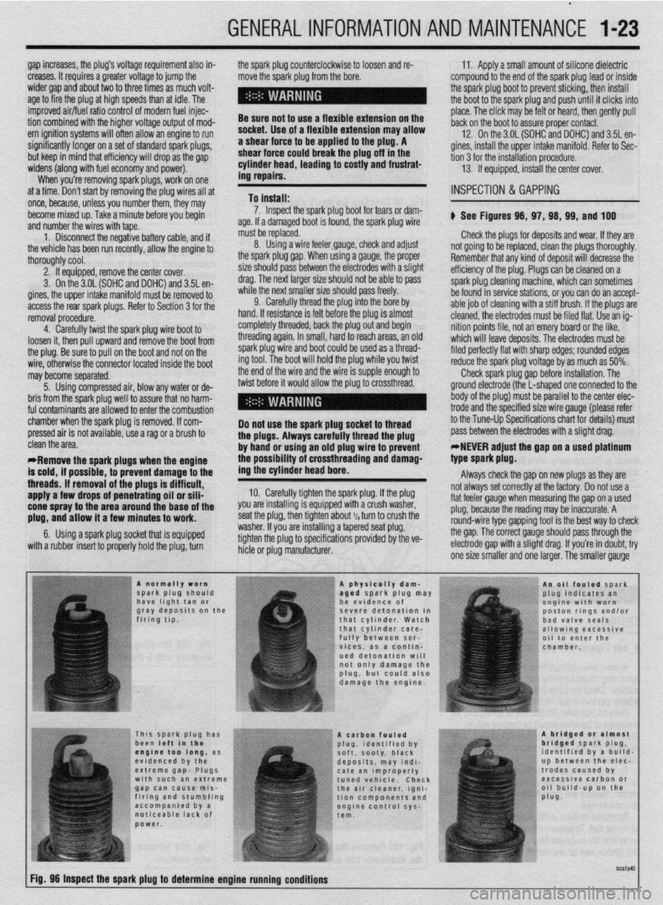
hicle or plug manufacturer. b See Figures 98, 97, 98, 99, and 100
not going to be replaced, clean the plugs thoroughly.
Remember that any kind of deposit will decrease the
efficiency of the plug. Plugs can be cleaned on a
spark plug cleaning machine, which can sometimes
be found in service stations, or you can do an accept-
able job of cleaning with a stiff brush. If the plugs are’
cleaned, the electrodes must be filed flat. Use an ig-
nition points file, not an emery board or the like,
which will leave deposits. The electrodes must be
filed perfectly flat with sharp edges; rounded edges
reduce the spark plug voltage by as much as 50%.
Check spark plug gap before installation. The
ground electrode (the L-shaped one connected to the
body of the plug) must be parallel to the center elec-
trode and the specified size wire gauge (please refer
to the Tune-Up Specifications chart for details) must
pass between the electrodes with a slight drag:
*,NEVER adjust the gap on a used platinum
. clean the area.
*Remove the spark plugs when the engine
is cold, if possible, to prevent damage to the
threads. If removal of the plugs is difficult,
apply a few drops of penetrating oil or sili-
cone spray to the area around the base of the
plug, and allow it a few minutes to work.
6. Using a spark plug socket that is equipped
with a rubber insert to properly hold the plug, turn type spark plug.
Always check the gap on new plugs as they are
not always set correctly at the factory. Do not use a
flat feeler gauge when measuring the gap on a used
plug, because the reading may be inaccurate. A
round-wire type gapping tool is the best way to check
the gap. The correct gauge should pass through the
electrode gap with a slight drag. If you’re in doubt, try
one size smaller and one laraer. The smaller aauqe
Page 29 of 408
.
l-30 GENERAL'INFORMATIONAND MAINTENANCE
n Pylon@ inserts, the clip
be removed prior to siidi then the insert can be re
After installing the replacement
strip and pull up while twisting counterclockwise.
The backing strip will snap out of the retaining tab.
Do this for the remaining tabs until the refill is free of
the blade. The length of these refills is molded into
the end and they should be replaced with identical
types. cate the front end is out of alignment or that the tires
are out of balance.
TIRE ROTATION
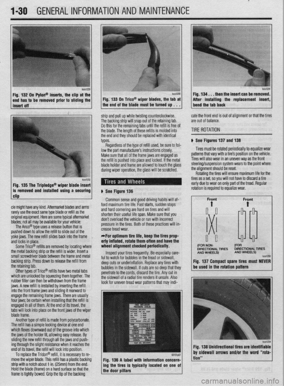
# See Figures 137 and 138
Tires must be rotated periodically to equalize wear
patterns that vary with a tire’s position on the vehicle.
Tires will also wear in an uneven way as the front
1 Fin 1% Tha Trinlarlna@
cle might have any kind. Aftermarket blades and arms
rarely use the exact same type blade or refill as the
original equipment. Here are some typiel aftermarket
blades; not all may be available for your vehicle:
The Anco@ type uses a release button that is
pushed down to allow the refill to slide out of the
yoke jaws. The new refill slides back into the frame
,
and locks in place.
Some Trico@ refills are removed by locating where
the metal backing strip or the refill is wider. Insert a
small screwdriver blade between the frame and metal
backing strip. Press down to release the refill from
the retaining tab.
Other types of Trico@’ refills have two metal tabs
which are unlocked by squeezing them together. The
rubber filler can then be withdrawn from the frame
iaws. A new refill is installed bv insertina the refill lowed to touch the olass steering/suspension system wears to the point where
the alianment should be reset.
# See Figure 138
Common sense and good driving habits will af-
ford maximum tire life. Fast starts, sudden stops
and hard cornering are hard on tires and will
shorten their useful life span. Make sure that you
don’t overload the vehicle or run with incorrect
pressure in the tires. Both of these practices will in-
crease tread wear.
*For optimum tire life, keep the fires prop
eriy inflated, rotate them often and have the
wheel alignment checked periodically.
Inspect your tires frequently. Be especially care-
ful to watch for bubbles in the tread or sidewall,
deep cuts or underinflation. Replace any tires with
bubbles in the sidewall. If cuts are so deep that they
penetrate to the cords, discard the tire. Any cut in
the sidewall of a radial tire renders it unsafe. Also
look for uneven tread wear patterns that may indi- Rotating the tires will ensure maximum life for the
tires as a set, so you will not have to discard a tire
early due to wear on only part of the tread. Regular
DIRECTIONAL TIRES DIRECTIONAL TIRES
jnto the front frame jaws and &ding it rearward to
engage the remaining frame jaws. There are usually
four jaws; be certain when installing that the refill is
engaged in all of them. At the end of its travel, the
tabs will lock into place on the front jaws of the wiper
blade frame.
Another type of refill is made from polycarbonate.
The refill has a simple locking device at one end
which flexes downward out of the groove into which
the jaws of the holder fit, allowing easy release. By
sliding the new refill through all the jaws and push-
ing through the slight resistance when it reaches the
end of its travel, the refill will lock into position.
To replace the Tridon@ refill, it is necessary to re-
move the wiper blade. This refill has a plastic backing
strip with a notch about 1 in. (25mm) from the end.
Hold the blade (frame) on a hard surface so that the
frame is tightly bowed. Grip the tip of the backing Fig. 138 A label with information concern-
ing the tires is typically located on one of
the door pillars
tion”
Page 86 of 408
ENGINEANDENGINEOVERHAUL 3-25
When removina the cvlinder head. take care
not to bend or iamag;! the plug guide. The
plug guide can not be replaced.
To install:
22. Thoroughly clean the mating surfaces of the
head and block.
23. Place a new head gasket on the cylinder
block with the identification marks facing upward. Do
not use sealer on the gasket.
24. Carefully install the cylinder head on the
block.
25. Measure the cylinder head bolts prior to in-
stallation Replace any that exceed 3.795 in.
(96.4mm)
26. Apply a small amount of engine oil to the
thread section of the bolt and install so the chamfer
of the washer faces upward.
27. Tighten the cylinder head bolts as follows:
a. In the proper tightening sequence, torque
bolts to 54 ft. Ibs. (75 Nm).
b. In the reverse order of the tightening se-
quence, fully loosen all bolts.
c In the proper trghtening sequence, torque
bolts to 14 ft. Ibs. (20 Nm).
d. In the proper tightening sequence, tighten
bolts 1/4 turn (90 degrees).
e. In the proper tightening sequence, tighten
bolts an additional 1/4 turn (90 degrees).
28. Install the camshaft sprocket and tighten the
bolt to 65 ft. Ibs (90 Nm), while holding the sprocket
in place using the appropriate wrench. Confirm
proper timing mark alignment.
29. Install the upper timing belt cover and rocker
cover. Torque the rocker cover bolts to 29 inch Ibs.
(3 Nm).
30. Loosen the water pipe mounting bolt for ease
of thermostat housing installation.
31. Apply a thin bead of sealant MD970389 or
equivalent, to the water tube connection on the ther-
mostat case.
32. Apply a small amount of water to the O-ring
of the water inlet pipe and press the thermostat case
assembly onto the water inlet pipe. Install the ther-
mostat case assembly mounting bolt tightening to 16
ff. Ibs. (22 Nm).
l ECT sensor and gauge sender l IAC motor 33. Tighten the water pipe mounting bolt.
34. Install the thermostat into the housing so the
jiggle valve is located at the top. Tighten the housing
bolts to 10 ft. Ibs (14 Nm).
35. Attach the wiring to the following compo-
nents:
l HO& sensor
l EGR temperature sensor l TP sensor l Knock sensor l Fuel injectors
36. Connect the upper radiator hose to the ther-
mostat housing.
37. Connect the accelerator cable connection to
the throttle body.
38. Connect the oil pressure switch.
39. Install the spark plug wires,
40. Connect the control harness assembly.
41. Replace the O-ring for the high pressure hose
and install a new clamp on the return hose and re-
connect the fuel lines. 42. Install the air intake hose. Connect the
breather hose and air cleaner case cover
43. Reconnect the brake booster and the PCV
vacuum hoses.
44. Fill the system with coolant.
45. Connect the negative battery cable
2.01 SOHC Engine
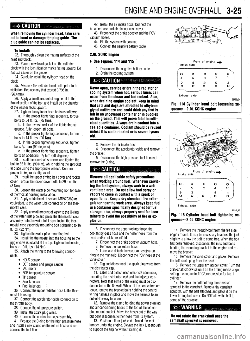
# See Figures 114 and 115
1. Disconnect the negative battery cable.
2. Drain the coolrng system.
Never open, service or drain the radiator or
cooling system when hot; serious burns can
occur from the steam and hot coolant. Also,
when draining engine coolant, keep in mind
that cats and dogs are attracted to ethylene
glycol antifreeze and could drink any that is
left in an uncovered container or in puddles
on the ground. This will prove fatal in suffi-
cient quantities. Always drain coolant into a
sealable container. Coolant should be reused
unless it is contaminated or is several years
old.
3. Remove the air intake hose.
4. Disconnect the accelerator cable and remove
the bracket.
5. Disconnect the high pressure fuel line and
remove the O-ring.
Observe all applicable safety precautions
when working around fuel. Whenever servic-
ing the fuel system, always work in a well
ventilated area. Do not allow fuel spray or
vapors to come in contact with a spark or
open flame. Keep a dry chemical fire extin-
guisher near the work area. Always keep fuel
in a container specifically designed for fuel
storage; also, always properly seal fuel con-
tainers to avoid the possibility of fire or ex-
plosion.
6. Disconnect the upper radiator hose, the
coolant by-pass hose and the heater hose from the
head and/or intake manifold.
7. Disconnect the brake booster vacuum hose.
8. Remove the fuel return hose.
9. Label and detach the vacuum hose(s) run-
ning to the manifold. Disconnect the PCV hose at the
valve cover.
10. Tag and disconnect the spark plug wires from
the drstnbutor cap
11. Label and detach each electrical connector,
including the distributor lead and the injector con-
nectors Note that some of the wiring must be drs-
connected at the firewall. When all the connectors are
loose, remove the bracket bolts holding the control
wiring harness rn place and move the harness to an
out-of-the-way location.
12. Remove the clamp holding the power steering
and air conditioning hoses to the top of the left en-
gine mount bracket. Move the hoses out of the way
but don’t drsconnect either hose from its system.
13. Position a floor lack and a broad piece of
lumber under the engine. Elevate the jack lust enough
to support the engine without raising it.
Front of engne I)
Intake side
~~
Exhaust side
93153~24 Fig. 114 Cylinder head bolt loosening se-
quence-2.01 SOHC engine
Front of engme I)
Intake side
Exhaust side
93153g25 Fig. 115 Cylinder head bolt tightening se-
quence-2.01 SDHC engine
14. Remove the through-bolt from the left side
engine mount. It may be necessary to adjust the jack
slightly to allow the bolt to come free When the bolt
has been removed, disconnect the nuts and bolts
holding the mounting bracket to the engine and re-
move the bracket
15. Remove the valve cover and gasket. Remove
the half-circle plug from the head.
16. Remove the upper timing belt cover. Turn the
crankshaft clockwise until all the timing marks align,
setting the engine to TDUcompression for No. 1
cylinder.
17. Remove the bolt holding the camshaft
sprocket to the camshaft. Remove the camshaft
sprocket, with the belt attached, and place it on the
lower timing belt cover. Do NOT allow the belt to
come off the sprocket
Do not rotate the crankshaft once the
camshaft sorocket is removed.
Page 97 of 408
3-36 ENGINEANDENGINEOVERHAUL
The EPA warns that urolonaed contact with
used engine oil may cause”a number of skin
disorders, including cancer! You should
make every effort to minimize your exposure
to
used engine oil. Protective gloves should
be worn when changing the oil. Wash your
hands and any other exposed skin areas as
soon as possible after exposure to
used en-
gine oil. Soap and water, or waterless hand
cleaner should be used.
4. Remove the solash shield from the wheel
93153p65 93153p60 well.
5. Remove the oil filter adapter.
6. Remove the lower and upper oil pans.
7. Remove the lower baffle, oil pump pick-up
and upper baffle.
8. Remove the oil pump case mounting bolts
and the oil pump case.
9. Remove the oil pump gear cover.
10. Make matchmarks on the oil pump rotors be-
fore removing them.
,,. r.-- -IL- -.( -L.11---‘I --. IL- -.I _ --
nemove me cranksnarr sear rrom me 011 pump
case.
To instell:
12. Install a new crankshaft seal in the oil pump
cover.
13. Apply engine oil to the rotors, then align the
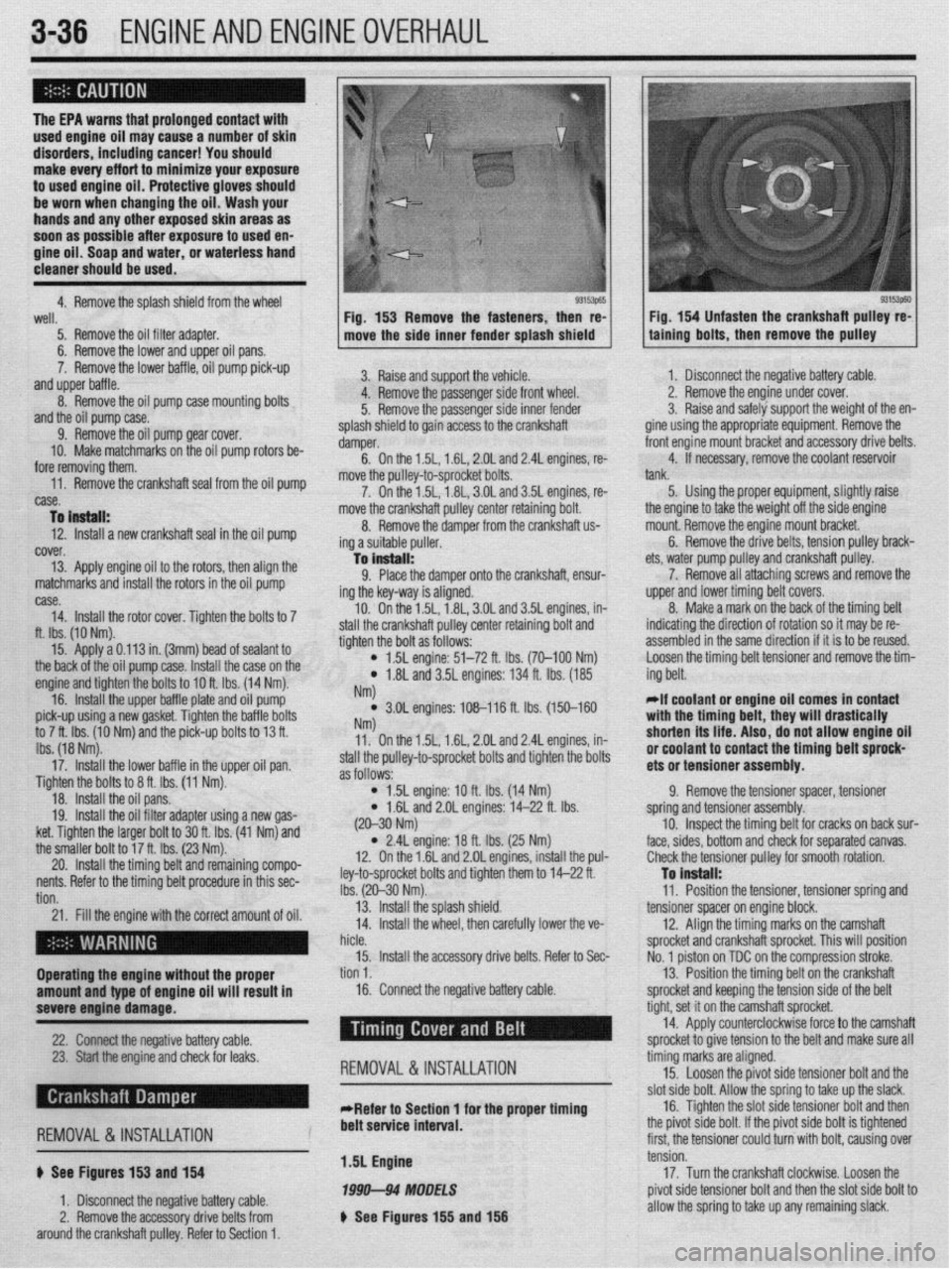
matchmarks and install the rotors in the oil pump Fig. 153 Remove the fasteners, then re-
move the side inner fender splash shield
3. Raise and support the vehicle.
4. Remove the passenger side front wheel.
5. Remove the passenger side inner fender
splash shield to gain access to the crankshaft
damper.
6. On the 1.5L, 1.6L, 2.OL and 2.4L engines, re-
move the oullev-to-sorocket bolts.
7. On thei .5L, i .8L, 3.OL and 3.5L engines, re-
move the crankshaft pulley center retaining bolt.
8. Remove the damper from the crankshaft us
ing a suitable puller.
-la install:
9. Place the damper onto the crankshaft, ensur-
ing the key-way is aligned.
10. On the 1.5L, 1.8L, 3.OL and 3.5L engines, in-
e crankshaft pulley center retaining bolt and
the bolt as follows: Fig. 154 Unfasten the crankshaft pulley re-
talning bolts, then remove the pulley
case.
14. Install the rotor cover. Tighten the bolts to 7
ft. Ibs. (10 Nm).
15. Apply a 0.113 in. (3mm) bead of sealant to
the back of the oil pump case. I[ -‘-‘I IL -~-- IL-
nsrall me ca
se on me engine and tighten the bolts to IOft Ihc 11 ,,, -. , .4 Nm).
16. Install the upper baffle r tlal te and oil pump
pick-up using a new gasket. Tic fhtti,, ,,lG va,,,ti ““a,., an tha hafflc, hnltc to 7 ft. Ibs. (10 Nm) and the pit k-up bolts to 13 ft.
Ibs. (18 Nm).
17. Install the lower baffle in the upper oil pan.
Tighten the bolts to 8 ft. Ibs. (11 Nm).
18. Install the oil pans.
19. Install the oil filter adapter using a new gas-
ket. Tighten the larger bolt to 30 ft. Ibs. (41 Nm) and
the smaller bolt to 1’ u ‘L- Inn ‘I--’ stall thl
tighten
4
) 1.5L engine: 51-72 ft. Ibs. (70-100 Nm)
l 1.8L and 3.5L engines: 134 ft. Ibs. (185
NM
l 3.OL engines: 108-116 ft. lbs. (150-160 NW 11. On the 1.5L, 1.6L, 2.OL and 2.4L engines, in-
stall the pulley-to-sprocket bolts and tighten the bolts
as follows:
l 1.5L engine: 10 ft. Ibs. (14 Nm)
* 1.6L and 2.OL engines: 14-22 ft. Ibs. 1. Disconnect the negative battery cable.
2. Remove the engine under cover.
3. Raise and safely support the weight of the en-
gine using the appropriate equipment. Remove the
front engine mount bracket and accessory drive belts.
4. If necessary, remove the coolant reservoir
tank.
5. Using the proper equipment, slightly raise
ets, water pump pulley
7. Remove all attr
upper and lower timin{
8. Make a mark o
indicating the directior
assembled in the same the engine to take the weight off the side engine
mount. Remove the engine mount bracket.
6. Remove the drive belts, tension pulley brack-
and crankshaft pulley.
aching screws and remove the
J belt covers.
n the back of the timing belt
I of rotation so it may be re-
! direction if it is to be reused.
tensioner and remove the tim-
Loosen the timing belt
ing belt.
*If coolant or engine oil comes in contact
with the timing bplt thaw will r(mcti~~llv Wll L, .,,s,, n,,, u,uu.,vu,,,
shorten its life. A ,IS o, do not allow engine oil
#.I nn..lr”* In rind In,
“I IruuI(IIIL Lu Irulll&t the timing belt sprock-
ets or tensioner assembly.
9. Remove the tensioner spacer, tensioner
spring and tensioner assembly.
cracks on back sur-
;eoarated canvas.
20. Install the tilllIllY uljllOllu IclllallllllY ~ullIPV-
:
nents. Refer to the timing belt procedure in this sec-
: tion.
21. Fill the engine with the correct amount of oil.
I . (20-30 Nm)
l 2.4L engine: 18 ft. Ibs. (25 Nm)
12. On the 1.6L and 2.OL engines, install the pul-
ley-to-sprocket bolts and tighten them to 14-22 ft.
Ibs. (20-30 Nm).
13. Install the splash shield.
14. Install the wheel, then carefully lower the ve- 10. Inspect the timing belt for I
face, sides, bottom and check for ! (
Check the tensioner pulley for smooth rotation.
To install:
11. Position the tensioner, tensioner spring and
tensioner spacer on engine block.
12. Align the timing marks on the camshaft
ft sprocket. This will position
tn the comoression stroke.
I hicle.
sprocket and cranksha
15. Install the accessory drive belts. Refer to Sec-
No. 1 piston on TDC o
Operating the engine without the proper tion 1.
13. Position the timing belt on the crankshaft
amount and type of engine oil will result in 16. Connect the negative battery cable.
sprocket and keeping the tension side of the bolt
severe engine damage.
-
22. -s
Chrmxt the nenntive h;lttm cnhle --, , I” ,.-J XL.._ I -..-., --I.-.
23. Start the engine and check for leaks.
REMOVAL &INSTALLATION
tight, set it on the cam, shaft sprocket.
14. Apply counterc Yockwise force to the camshaft
snrnckd tn nive tensin In -r .__.._. ._ J..- ._ - _ to the belt and make sure all
timing marks are aligned.
15. Loosen the pivot side tensioner bolt and the
clnt
&In hnlt Allnur thn rnrinn tn tdm III-I thn slack, cl then , d I, I’ r),“I 44”” ““IL. “ll”sl LllU .y”“yj L” L”I\U Low Ul” L .-Refer to Section 1 for the proper timing 16. Tighten the slot side tensioner bolt ark
., , , , ,, ,, ,, , , , , ,, . ,, ,~
REMOVAL &INSTALLATION
6 See Figures 153 and 154
1. Disconnect the negative battery cable.
2. Remove the accessory drive belts from
around the crankshaft pulley. Refer to Section 1. belt service interval.
1.5L Engine
1999-94 MODELS
b See Figures 155 and 156 me p~vor sloe DOI~. IT me p~vor sloe OOII
IS ogntened
first, the tensioner could turn with bolt, causing over
tension.
17. Turn the crankshaft clockwise. Loosen the
pivot side tensioner bolt and then the slot side bolt to
allow the spring to take up any remaining slack.
Page 98 of 408
ENGINEANDENGINEOVERHAUL 3-37
1. Ben
2. Power4teerlna Dump 7. washer
8. Crankshaft pullet
9. Damper pulls
10. upper ccwer
11. Lowercowr
12. llmingbeil
13. crsnkshat? E#ocket 14. Flsnge
i 5. Tensbner spacer
16. Tef~kner WkW
1; Tgibnrr
19: camehan sprocket
91251ga
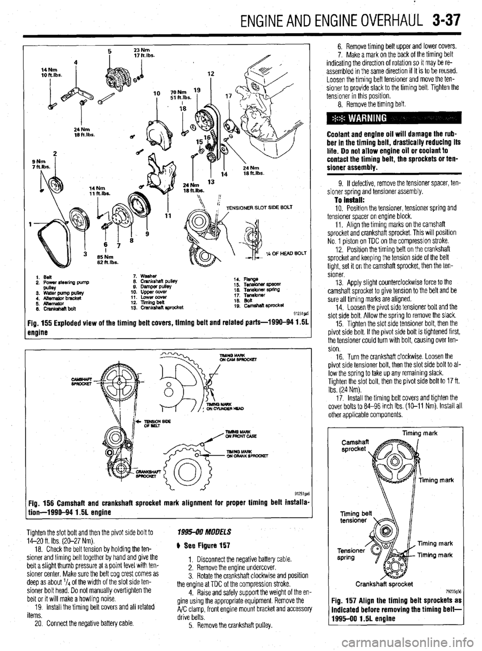
Fig. 155 Exploded view of the timing belt covers, timing belt and related parts-1990-94 1.51
engine
Fig. 156 Camshaft and crankshaft sprocket mark alignment for proper timing belt installa-
tion-1990-94 1.51 engine
Tighten the slot bolt and then the pivot side bolt to
14-20 ft. Ibs. (20-27 Nm).
18. Check the belt tension by holding the ten-
sioner and timing belt together by hand and give the
belt a slight thumb pressure at a point level with ten-
sioner center. Make sure the belt cog crest comes as
deep as about l/4 of the width of the slot side ten-
sioner bolt head. Do not manually overtighten the
belt or it will make a howling noise.
19. Install the timing belt covers and all related
items. 1995-00 MOOFLS
) See Figure 157
1. Disconnect the negative battery cable.
2. Remove the engine undercover.
3. Rotate the crankshaft clockwlse and position
the engine at TDC of the compression stroke.
4. Raise and safely support the weight of the en-
gine using the appropriate equipment. Remove the
A/C clamp, front engine mount bracket and accessory
drive belts.
20. Connect the negative battery cable.
5. Remove the crankshaft pulley. 6. Remove timing belt upper and lower covers.
7. Make a mark on the back of the timing belt
indicating the direction of rotation so it may be re-
assembled in the same direction if it is to be reused.
Loosen the timing belt tensioner and move the ten-
sioner to provide slack to the timing belt. Tighten the
tensioner in this position.
8. Remove the timing belt.
Coolant and engine oil will damage the rub-
ber in the timing belt, drastically reducing its
life. Do not allow engine oil or coolant to
contact the timing belt, the sprockets or ten-
sioner assembly.
9. If defective, remove the tensioner spacer, ten-
sioner spring and tensioner assembly.
To install: 10. Position the tensioner, tensioner spring and
tensioner spacer on engine block.
11. Align the timing marks on the camshaft
sprocket and crankshaft sprocket. This will position
No. 1 piston on TDC on the compression stroke.
12. Position the timing belt on the crankshaft
sprocket and keeping the tension side of the belt
tight, set it on the camshaft sprocket, then the ten-
sioner.
13. Apply slight counterclockwise force to the
camshaft sprocket to give tension to the belt and be
sure all timing marks are aligned.
14. Loosen the pivot side tensioner bolt and the
slot side bolt. Allow the spring to remove the slack.
15. Tighten the slot side tensioner bolt, then the
pivot side bolt. If the pivot side bolt is tightened first,
the tensioner could turn with bolt, causing over ten-
sion.
16. Turn the crankshaft clockwise. Loosen the
pivot side tensioner bolt, then the slot side bolt to al-
low the spring to take up any remaining slack.
Tighten the slot bolt, then the pivot side bolt to 17 ft.
Ibs. (24 Nm).
17. Install the timing belt covers and tighten the
cover bolts to 84-96 inch Ibs. (E-11 Nm). Install all
other applicable components.
liming mark
ming mark
Timing mark
Timing mark
Crankshaft sprocket
79235g5t Fig. 157 Align the timing belt sprockets as
indicated before removing the timing belt-
1995-00 1.51 engine
Page 99 of 408
3-38 ENGINEANDENGINEOVERHAUL
1.61&? 2.OL (Non-Turbo) DOHC Engines
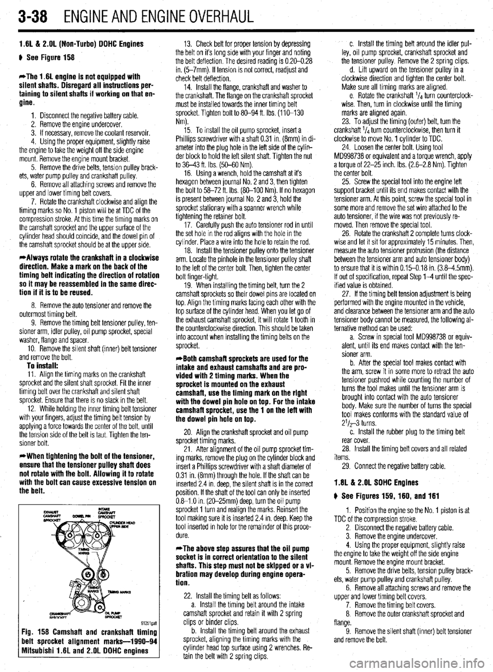
g See Figure 158
*The 1.6L engine is not equipped with
silent shafts. Disregard all instructions per-
taining to silent shafts if working on that en-
gine.
1. Disconnect the negative battery cable.
2. Remove the engine undercover.
3. If necessary, remove the coolant reservoir.
4. Using the proper equipment, slightly raise
the engine to take the weight off the side engine
mount. Remove the engine mount bracket.
5. Remove the drive belts, tension pulley brack-
ets, water pump pulley and crankshaft pulley.
6. Remove all attaching screws and remove the
upper and lower timing belt covers.
7. Rotate the crankshaft clockwise and align the
timing marks so No. 1 piston will be at TDC of the
compression stroke. At this time the timing marks on
the camshaft sprocket and the upper surface of the
cylinder head should coincide, and the dowel pin of
the camshaft sprocket should be at the upper side.
*Always rotate the crankshaft in a clockwise
direction. Make a mark on the back of the
timing belt indicating the direction of rotation
so it may be reassembled in the same direc-
tion if it is to be reused.
8. Remove the auto tensioner and remove the
outermost timing belt.
9. Remove the timing belt tensioner pulley, ten-
sioner arm, idler pulley, oil pump sprocket, special
washer, flange and spacer.
10. Remove the silent shaft (inner) belt tensioner
and remove the belt.
To install: 11. Align the timing marks on the crankshaft
sprocket and the silent shaft sprocket. Fit the inner
timing belt over the crankshaft and silent shaft
sprocket. Ensure that there is no slack in the belt.
12. While holding the inner timing belt tensioner
with your fingers, adjust the timing belt tension by
applying a force towards the center of the belt, until
the tension side of the belt is taut. Tighten the ten-
sioner bolt.
*When tightening the bolt of the tensioner,
ensure that the tensioner pulley shaft does
not rotate with the bolt. Allowing it to rotate
with the bolt can cause excessive tension on
the belt.
13. Check belt for proper tension by depressing
the belt on it’s long side with your finger and noting
the belt deflection. The desired reading is 0.20-0.28
in. (5-7mm). If tension is not correct, readjust and
check belt deflection.
14. Install the flange, crankshaft and washer to
the crankshaft. The flange on the crankshaft sprocket
must be installed towards the inner trming belt
sprocket. Tighten bolt to 80-94 ft. Ibs. (110-130
Nm).
15. To install the oil pump sprocket, insert a
Phillips screwdriver with a shaft 0.31 in. (8mm) in di-
ameter into the plug hole in the left side of the cylin-
der block to hold the left silent shaft. Tighten the nut
to 36-43 ft. Ibs. (50-60 Nm).
16. Using a wrench, hold the camshaft at it’s
hexagon between journal No. 2 and 3, then tighten
the bolt to 58-72 ft. Ibs. (80-100 Nm). If no hexagon
is present between journal No. 2 and 3, hold the
sprocket stationary with a spanner wrench while
tightening the retainer bolt.
17. Carefully push the auto tensioner rod in until
the set hole in the rod aligns with the hole in the
cylinder. Place a wire into the hole to retain the rod.
18. Install the tensioner pulley onto the tensioner
arm. Locate the pinhole in the tensioner pulley shaft
to the left of the center bolt. Then, tighten the center
bolt finger-tight.
19. When installing the timing belt, turn the 2
camshaft sprockets so their dowel pins are located on
top. Align the timing marks facing each other with the
top surface of the cylinder head. When you let go of
the exhaust camshaft sprocket, it will rotate 1 tooth in
the counterclockwise direction. This should be taken
into account when installing the timing belts on the
sprocket.
*Both camshaft sprockets are used for the
intake and exhaust camshafts and are pro-
vided with 2 timing marks. When the
sprocket is mounted on the exhaust
camshaft, use the timing mark on the right
with the dowel pin hole on top. For the intake
camshafl sprocket, use the 1 on the left with
the dowel pin hole on top.
20. Align the crankshaft sprocket and oil pump
sprocket timing marks.
21. After alignment of the oil pump sprocket tim-
ing marks, remove the plug on the cylinder block and
insert a Phillips screwdriver with a shaft diameter of
0.31 in. (8mm) through the hole. If the shaft can be
inserted 2.4 in. deep, the silent shaft is in the correct
position. If the shaft of the tool can only be inserted
0.61 .O in. (2C-25mm) deep, turn the oil pump
sprocket 1 turn and realign the marks. Reinsert the
tool making sure it is inserted 2.4 in. deep. Keep the
tool inserted in hole for the remainder of this proce-
dure.
*The above step assures that the oil pump
socket is in correct orientation to the silent
shafts. This step must not be skipped or a vi-
bration may develop during engine opera-
tion.
22. Install the timing belt as follows:
a. Install the timing belt around the intake
camshaft sprocket and retain it with 2 spring
clips or binder clips.
b. Install the timing belt around the exhaust
sprocket, aligning the timing marks with the
cylinder head top surface using 2 wrenches. Re-
tain the belt with 2 spring clips. c. Install the timing belt around the idler pul-
ley, oil pump sprocket, crankshaft sprocket and
the tensioner pulley. Remove the 2 spring clips.
d. Lift upward on the tensioner pulley in a
clockwise direction and tighten the center bolt.
Make sure all timing marks are aligned.
e. Rotate the crankshaft ‘14 turn counterclock-
wise. Then, turn in clockwise until the timing
marks are alrgned again.
23. To adjust the timing (outer) belt, turn the
crankshaft ‘14 turn counterclockwise, then turn it
clockwise to move No. 1 cylinder to TDC.
24. Loosen the center bolt. Using tool
MD998738 or equivalent and a torque wrench, apply
a torque of 22-25 inch. Ibs. (2.6-2.8 Nm). Tighten
the center bolt.
25. Screw the special tool into the engine left
support bracket until its end makes contact with the
tensioner arm. At this point, screw the special tool in
some more and remove the set wire attached to the
auto tensioner, if the wire was not previously re-
moved. Then remove the specral tool.
26. Rotate the crankshaft 2 complete turns clock-
wise and let it sit for approximately 15 minutes. Then,
measure the auto tensioner protrusion (the distance
between the tensioner arm and auto tensioner body)
to ensure that it is within 0.15-0.18 in. (3.8-4.5mm).
If out of specification, repeat Step l-4 until the spec-
ified value is obtained.
27. If the timing belt tension adjustment is being
performed with the engine mounted in the vehicle,
and clearance between the tensioner arm and the auto
tensioner body cannot be measured, the following al-
ternative method can be used:
a. Screw in special tool MD998738 or equiv-
alent, until its end makes contact with the ten-
sioner arm.
b. After the special tool makes contact with
the arm, screw it in some more to retract the auto
tensioner pushrod while counting the number of
turns the tool makes until the tensioner arm is
brought into contact with the auto tensioner
body. Make sure the number of turns the special
tool makes conforms with the standard value of
21/a-3 turns.
c. Install the rubber plug to the timing belt
rear cover.
28. Install the timing belt covers and all related
items.
29. Connect the negative battery cable.
1.8L & 2.OL SOHC Engines
g See Figures 159, 160, and 161
1. Position the engine so the No. 1 piston is at
TDC of the compression stroke.
2. Disconnect the negative battery cable.
3. Remove the engine undercover.
4. Using the proper equipment, slightly raise
the engine to take the weight off the side engine
mount. Remove the engine mount bracket.
5. Remove the drive belts, tension pulley brack-
ets, water pump pulley and crankshaft pulley.
6. Remove all attaching screws and remove the
upper and lower timing belt covers.
7. Remove the timing belt covers.
8. Remove the outer crankshaft sprocket and
flange.
9. Remove the silent shaft (inner) belt tensioner
and remove the belt.
Page 100 of 408
.
ENGlNEANDENGlliEOVERHAUL 3-39
To install: IO. Align the timing marks of the silent shaft
sprockets and the crankshaft sprocket with the timing
marks on the front case.
11. Wrap the timing belt around the sprockets so
there is no slack in the upper span of the belt and the
timing marks are still aligned.
12. Install the tensioner pulley and move the pul-
ley by hand so the long side of the belt deflects about
l/d in. (6mm).
13. Hold the pulley tightly so the pulley cannot
rotate when the bolt is tightened. Tighten the bolt to
15 ft. Ibs. (20 Nm) and recheck the deflection
amount.
14. Install the timing belt tensioner fully toward
the water pump and tighten the bolts. Place the upper
end of the spring against the water pump body.
15. Align the timing marks of the camshaft,
crankshaft and oil pump sprockets with their corre-
sponding marks on the front case or rear cover.
*There is a possibility to align all timing
marks and have the oil pump sprocket and
silent shaft out of time, causing an engine vi-
bration during operation. If the following step
is not followed exactly, there is a 50 percent
chance that the silent shaft alignment will be
180 degrees off.
16. Before installing the timing belt, ensure that
the left side (rear) silent shaft (oil pump sprocket) is
in the correct position as follows:
a. Remove the plug from the rear side of the
block and insert a tool with shaft diameter of
0.31 in. (8mm) into the hole.
b. With the timing marks still aligned, the
shaft of the tool must be able to go in at least
2’13 in. (59mm). If the tool can only go in about
1 in. (25mm), the shaft is not in the correct ori-
entation and will cause a vibration during engine
operation. Remove the tool from the hole and
turn the oil pump sprocket 1 complete revolution.
Realign the timing marks and insert the tool. The
shaft of the tool must go in at least 21/3 in.
(59mm).
c. Recheck and realign the timing marks.
d. Leave the tool in place to hold the silent
shaft while continuing
17. Install the belt to the crankshaft sprocket, oil
pump sprocket, then camshaft sprocket, in that order.
While doing so, make sure there is no slack between
the sprocket except where the tensioner is installed.
18. Recheck the timing marks’alignment. If all
are aligned, loosen the tensioner mounting bolt and
allow the tensioner to apply tension to the belt.
E
91251gbl
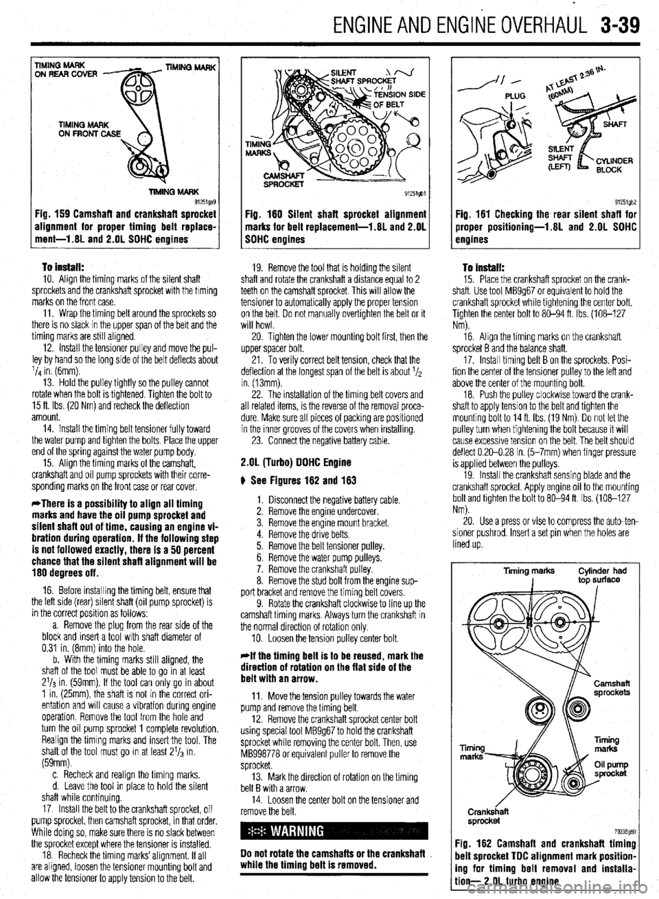
Fig. 180 Silent shaft sprocket alignment
marks for belt replacement-l.81 and 2.OL
SOHC engines
19. Remove the tool that is holding the silent
shaft and rotate the crankshaft a distance equal to 2
teeth on the camshaft sprocket. This will allow the
tensioner to automatically apply the proper tension
on the belt. Do not manually overtighten the belt or it
will howl.
20. Tighten the lower mounting bolt first, then the
upper spacer bolt.
21. To verify correct belt tension, check that the
deflection at the longest span of the belt is about 1/2
in. (13mm).
22. The installation of the timing belt covers and
all related items, is the reverse of the removal proce-
dure. Make sure all pieces of packing are positioned
in the inner grooves of the covers when installing.
23. Connect the negative battery cable.
2.OL (Turbo) OOHC Engine
ti See Figures 162 and 163
1. Disconnect the negative battery cable.
2. Remove the engine undercover.
3. Remove the engine mount bracket.
4. Remove the drive belts.
5. Remove the belt tensioner pulley.
6. Remove the water pump pulleys.
7. Remove the crankshaft pulley.
8. Remove the stud bolt from the engine sup-
port bracket and remove the timing belt covers.
9. Rotate the crankshaft clockwise to line up the
camshaft timing marks. Always turn the crankshaft in
the normal direction of rotation only.
10. Loosen the tension pulley center bolt.
*If the timing belt is to be reused, mark the
direction of rotation on the flat side of the
belt with an arrow.
11. Move the tension pulley towards the water
pump and remove the timing belt.
12. Remove the crankshaft sprocket center bolt
using special tool MB9g67 to hold the crankshaft
sprocket while removing the center bolt. Then, use
MB998778 or equivalent puller to remove the
sprocket.
13. Mark the direction of rotation on the timing
belt B with a arrow.
14. Loosen the center bolt on the tensioner and
remove the belt.
00 not rotate the camshafts or the crankshafl
while the timing belt is removed.
/--- PLUG
91251gb2 Fig. 161 Checking the rear silent shafl for
jroper positioning-1.8L and 2.OL SOHC
Pnoines
To Install:
15. Place the crankshaft sprocket on the crank-
shaft. Use tool MB9g67 or equivalent to hold the
crankshaft sprocket while tightening the center bolt.
Tighten the center bolt to 80-94 ft. Ibs. (108-127
Nm).
16. Align the timing marks on the crankshaft
sprocket B and the balance shaft.
17. Install timing belt B on the sprockets. Posi-
tion the center of the tensioner pulley to the left and
above the center of the mounting bolt.
18. Push the pulley clockwise toward the crank-
shaft to apply tension to the belt and tighten the
mounting bolt to 14ft. Ibs. (19 Nm) Do not let the
pulley turn when tightening the bolt because it will
cause excessive tension on the belt. The belt should
deflect 0.20-0.28 in. (5-7mm) when finger pressure
is applied between the pulleys.
19. Install the crankshaft sensing blade and the
crankshaft sprocket. Apply engine oil to the mounting
bolt and tighten the bolt to 80-94 ft. Ibs. (108-127
Nm).
20. Use a press or vise to compress the auto-ten-
sioner pushrod, Insert a set pin when the holes are
lined up.
Tming marks Cylinder had
I top surface
Ti
m
Crank&aft
sprocket
79235g60 :ig. 162 Camshaft and crankshaft timing
lelt sprocket TOC alignment mark position-
ng for timing belt removal and installa-
ion- 2.OL turbo engine
Page 105 of 408
.
3-44 ENGINEANDENGINEOVERHALJL
31. Connect the negative battery cable.
32. Road test the vehicle.
EXCEPT 1992-94 MODELS
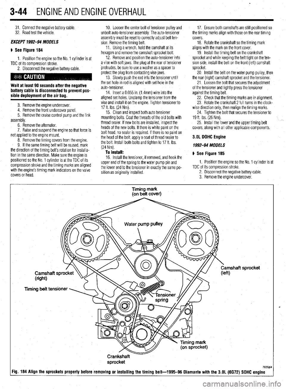
$ See Figure 184
1. Position the engine so the No. 1 cylinder is at
TDC of its compression stroke.
2. Disconnect the negative battery cable.
Wait at least 90 seconds after the negative
battery cable is disconnected to prevent pos-
sible deployment of the air bag.
3. Remove the engine undercover.
4. Remove the front undercover panel.
5. Remove the cruise control pump and the link
assembly.
6. Remove the alternator.
7. Raise and suspend the engine so that force is
not applied to the engme mount,
8. Remove the timing covers from the engine.
9. If the same timing belt will be reused, mark
the direction of the timing belt’s rotation for installa-
tion in the same direction. Make sure the engine is
positroned so the No. 1 cylinder is at the TDC of its
compression stroke and the timing marks are aligned
with the engine’s timing mark indicators on the valve
covers or head. 10. Loosen the center bolt of tensioner pulley and
unbolt auto-tensioner assembly The auto-tensioner
assembly must be reset to correctly adjust belt ten-
sion. Remove the timing belt.
11. Using a wrench, hold the camshaft at its
hexagon and remove the camshaft sprocket bolt.
12. Remove and position the auto-tensioner into
a vise with soft jaws. The plug at the rear of tensioner
protrudes, be sure to use a washer as a spacer to
protect the plug from contacting vise jaws.
13. Slowly push the rod Into the tensioner until
the set hole rn rod is aligned with set hole in the
auto-tensioner.
14. Insert a 0.055 in. (1.4mm) wire into the
aligned set holes. Unclamp the tensioner from the
vise and install it on the engine. Trghten tensroner to
17 ft. Ibs. (24 Nm).
15. Clean and inspect both auto tensioner
mounting bolts. Coat the threads of the old bolts with
thread sealer. If new bolts are installed, Inspect the
heads of the new bolts. If there is white paint on the
bolt head, no sealer is required. If there is no parnt on
the head of the bolt, apply a coat of thread sealer to
the bolt. Install both bolts and tighten to 17 ft. Ibs.
(24 Nm).
To install: 16. Install the tensioner, if removed, and hook the
upper end of the spring to the water pump pin and
the lower end to the tensioner in exactly the same po-
sition as originally installed. 17. Ensure both camshafts are still positioned so
the timing marks align with those on the rear timing
covers.
18. Rotate the crankshaft so the timing mark
aligns with the mark on the front cover.
19. Install the timing belt on the crankshaft
sprocket and while keeping the belt tight on the ten-
sion side, mstall the belt on the front (left) camshaft
sprocket.
20 Install the belt on the water pump pulley, then
the rear (right) camshaft sprocket and the tensioner.
21. Loosen the bolt that secures the adjustment
of the tensioner and lightly press the tensioner
against the timing belt.
22. Check that the timing marks are in alignment.
23 Rotate the crankshaft 2 full turns in the clock-
wise direction only, then realign the timing marks,
24. Tighten the bolt that secures the tensioner to
19 ft. Ibs. (26 Nm).
25. install the lower and the upper timing belt
covers, along with all other applicable components.
3.OL DDHC Engine
1992-94 MODELS
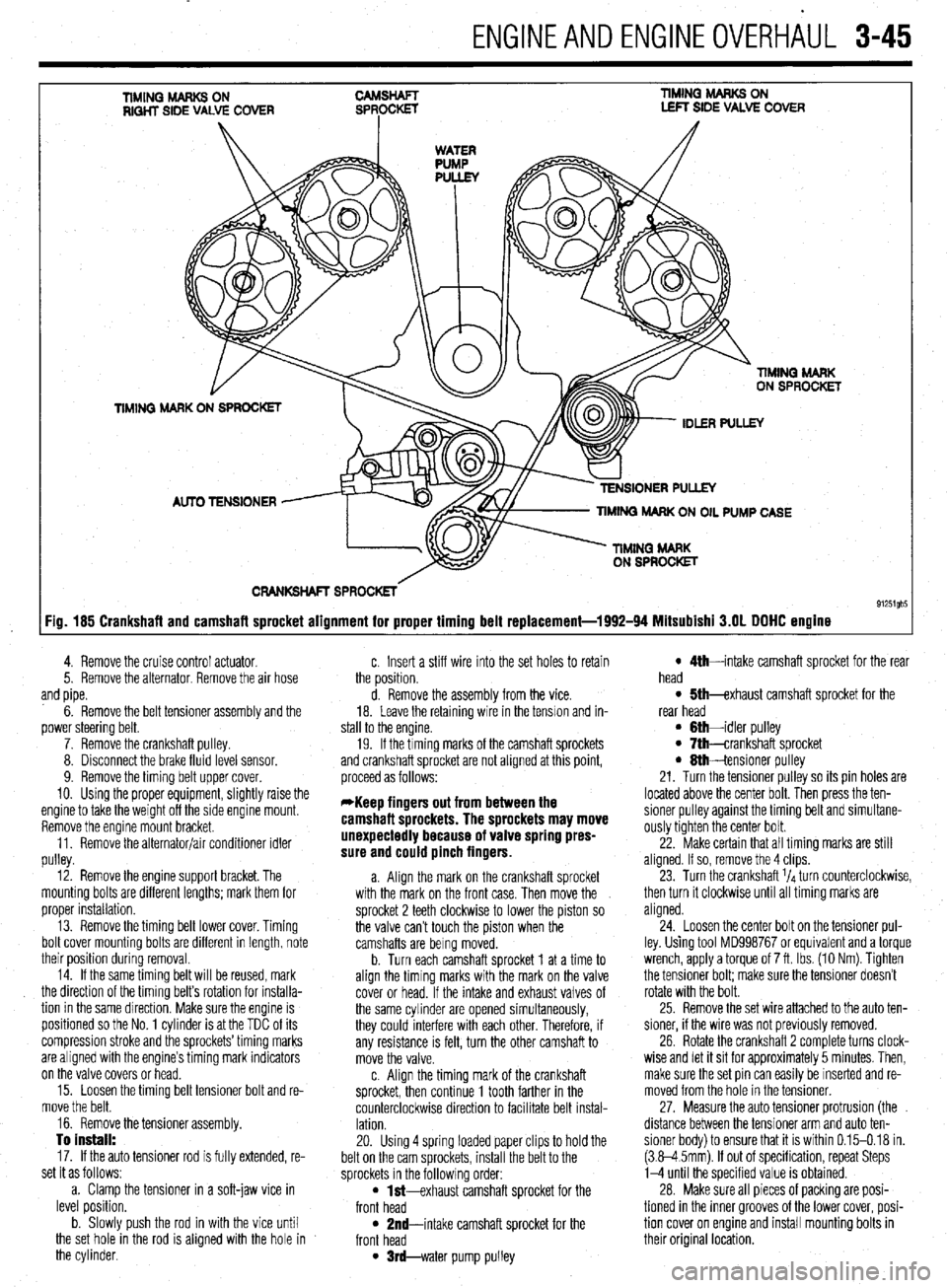
# See Figure 185
1. Position the engine so the No. 1 cylinder is at
TDC of its compression stroke.
2. Disconnect the negative battery cable.
3. Remove the engine undercover.
Timing mark
(on belt cover)
Timing belt tensioner
Crankshaft
sprocket
7923W :ig. 184 Align the sprockets properly before removing or installing the timing belt-1995-96 Diamante with the 3.OL (6672) SDHC engine
Page 106 of 408
ENGlNEANDENGlNEOVERHiUL 3-45
TIMINQ MARKS ON RIQHT SIDE VALVE COVER TIMING MARKS ON LEFT SIDE VALVE COVER
CRANKSHAFT SPROCKETS
91251gb5 :ig. 185 Crankshaft and camshaft sprocket alignment for proper timing belt replacement-1992-94 Mitsubishi 3.OL DOHC engine
4. Remove the cruise control actuator.
5. Remove the alternator. Remove the air hose
and pipe.
6. Remove the belt tensioner assembly and the
power steering belt.
7. Remove the crankshaft pulley.
8. Disconnect the brake fluid level sensor.
9. Remove the timing belt upper cover.
10. Using the proper equipment, slightly raise the
engine to take the weight off the side engine mount.
Remove the engine mount bracket.
11. Remove the alternator/air conditioner idler
pulley.
12. Remove the engine support bracket. The
mounting bolts are different lengths; mark them for
proper installation.
13. Remove the timing belt lower cover. Timing
bolt cover mounting bolts are different in length, note
their position during removal.
14. If the same timing belt will be reused, mark
the direction of the timing belt’s rotation for installa-
tion in the same dlrection. Make sure the engine is
positioned so the No. 1 cylinder is at the TDC of its
compression stroke and the sprockets’timing marks
are aligned with the engine’s timing mark indicators
on the valve covers or head.
15. Loosen the timing belt tensioner bolt and re-
move the belt.
16. Remove the tensioner assembly.
To install:
17. If the auto tensioner rod is fully extended, re-
set it as follows:
a. Clamp the tensioner in a soft-jaw vice in
level position.
b. Slowly push the rod in with the vice until
the set hole in the rod is aligned with the hole in
the cylinder. c. Insert a stiff wire into the set holes to retain
the position.
d. Remove the assembly from the vice.
18. Leave the retaining wire in the tension and in-
stall to the engine.
19. If the timing marks of the camshaft sprockets
and crankshaft sprocket are not aligned at this point,
proceed as follows:
*Keep fingers out from between the
camshaft sprockets. The sprockets may move
unexpectedly because of valve spring pres-
sure and could pinch fingers.
a. Align the mark on the crankshaft sprocket
with the mark on the front case. Then move the
sprocket 2 teeth clockwise to lower the piston so
the valve can’t touch the piston when the
camshafts are being moved.
b. Turn each camshaft sprocket 1 at a time to
align the timing marks with the mark on the valve
cover or head. If the intake and exhaust valves of
the same cylinder are opened simultaneously,
they could interfere with each other. Therefore, if
any resistance is felt, turn the other camshaft to
move the valve.
c. Align the timing mark of the crankshaft
sprocket, then continue 1 tooth farther in the
counterclockwise direction to facilitate belt instal-
lation.
20. Using 4 spring loaded paper clips to hold the
belt on the cam sprockets, install the belt to the
sprockets in the following order:
l M-exhaust camshaft sprocket for the
front head
l 2nd-intake camshaft sprocket for the
front head
l trd-water pump pulley
l 5th-exhaust camshaft sprocket for tile
rear head
l Ah-intake camshaft sprocket for the rear
l Gth-idler pulley head l 7th-crankshaft sprocket l 8th-tensioner pulley
21. Turn the tensioner pulley so its pin holes are
located above the center bolt. Then press the ten-
sioner pulley against the timing belt and simultane-
ously tighten the center bolt.
22. Make certain that all timing marks are still
aligned. If so, remove the 4 clips.
23. Turn the crankshaft l/d turn counterclockwise,
then turn it clockwise until all timing marks are
aligned.
24. Loosen the center bolt on the tensioner pul-
ley. Using tool MD998767 or equivalent and a torque
wrench, apply a torque of 7 ft. Ibs. (10 Nm). Tighten
the tensioner bolt; make sure the tensioner doesn’t
rotate with the bolt.
25. Remove the set wire attached to the auto ten-
sioner, if the wire was not previously removed.
26. Rotate the crankshaft 2 complete turns clock-
wise and let it sit for approximately 5 minutes. Then,
make sure the set pin can easily be inserted and re-
moved from the hole in the tensioner.
27. Measure the auto tensioner protrusion (the
distance between the tensioner arm and auto ten-
sioner body) to ensure that it is within 0.15-0.18 in.
(3.8-4 5mm). If out of specification, repeat Steps
l-4 until the specified value is obtained.
28. Make sure all pieces of packing are posi-
tioned in the inner grooves of the lower cover, posi-
tion cover on engine and install mounting bolts in
their original location.