brake fluid MITSUBISHI DIAMANTE 1900 Repair Manual
[x] Cancel search | Manufacturer: MITSUBISHI, Model Year: 1900, Model line: DIAMANTE, Model: MITSUBISHI DIAMANTE 1900Pages: 408, PDF Size: 71.03 MB
Page 2 of 408
.
1-2 GENERALINFORMATIONAND MAINTENANCE
Chitton’s Total Car Care manual for the 199M10
Mitsubishi Mirage, Galant and Diamante is intended
to help you learn more about the inner workings of
your vehicle while saving you money on its upkeep
and operation.
The beginning of the book will likely be referred to
the most, since that is where you will find information
for maintenance and tune-up. The other sections deal
with the more complex systems of your vehicle. Oper-
ating systems from engine through brakes are cov-
ered to the extent that the average do-it-yourselfer be-
comes mechanically involved. This book will not
explain such things as rebuilding a differential for the
simple reason that the expertise required and the in-
vestment in special tools make this task uneconomi-
cal. It will, however, give you detailed instructions to
help you change your own brake pads and shoes, re-
place spark plugs, and perform many more jobs that
can save you money, give you personal satisfaction
and help you avoid expensive problems.
A secondary purpose of this book is a reference for
owners who want to understand their vehicle and/or
their mechanics better. In this case, no tools at all are
required.
Before removing any bolts, read through the entire
procedure. This will give you the overall view of what
tools and supplies will be required. There is nothing
more frustrating than having to walk to the bus stop
on Monday morning because you were short one bolt
on Sunday afternoon. So read ahead and plan ahead.
Each operation should be approached logically and
all procedures thoroughly understood before attempt-
ing any work.
All sections contain adjustments, maintenance, re-
moval and installation procedures, and in some cases,
repair or overhaul procedures. When repair is not con-
sidered practical, we tell you how to remove the part
and then how to install the new or rebuilt replacement.
In this way, you at least save labor costs. “Backyard”
repair of some components is just not practical.
Many procedures in this book require you to “label
and disconnect. . ” a group of lines, hoses or wires.
Don’t be lulled into thinking you can remember where
everything goes-you won’t. If you hook up vacuum
or fuel lines incorrectly, the vehicle may run poorly, if
at all. If you hook up electrical wiring incorrectly, you
may instantly learn a very expensive lesson.
You don’t need to know the official or engineering
name for each hose or line. A piece of masking tape
on the hose and a piece on its fitting will allow you to
assign your own label such as the letter A or a short name. As long as you remember your own code, the
lines can be reconnected by matching similar letters
or names. Do remember that tape will dissolve in
gasolrne or other fluids; if a component is to be
washed or cleaned, use another method of identifica-
tion. A permanent felt-tipped marker or a metal scribe
can be very handy for marking metal parts. Remove
any tape or paper labels after assembly.
It’s necessary to mention the difference between
maintenance and repair Maintenance includes rou-
tine inspections, adjustments, and replacement of
parts which show signs of normal wear Maintenance
compensates for wear or deterioration. Repair implies
that something has broken or is not working. A need
for repair is often caused by lack of maintenance. Ex-
ample, draining and refilling the automatic transaxle
fluid is maintenance recommended by the manufac-
turer at specific mileage intervals. Failure to do this
can shorten the life of the transmission/transaxle, re-
quiring very expensive repairs. While no maintenance
program can prevent items from breaking or wearing
out, a general rule can be stated: MAINTENANCE IS
CHEAPER THAN REPAIR.
Two basic mechanrc’s rules should be mentioned
here. First, whenever the left side of the vehicle or en-
gine is referred to, it is meant to specify the drivers
side. Conversely, the right side of the vehicle means
the passengers side. Second, screws and bolts are
removed by turning counterclockwise, and tightened
by turning clockwrse unless specifically noted.
Safety is always the most important rule. Con-
stantly be aware of the dangers involved in working
on an automobile and take the proper precautions.
See the informatron in this section regarding SER-
VICING YOUR VEHICLE SAFELY and the SAFETY
NOTICE on the acknowledgment page.
Pay attention to the instructions provided. There
are 3 common mistakes in mechanical work:
1. Incorrect order of assembly, disassembly or
adjustment. When taking something apart or putting
it together, performing steps in the wrong order usu-
ally just costs you extra time; however, it CAN break
something. Read the entire procedure before begin-
ning disassembly. Perform everything in the order in
which the instructions say you should, even if you
can’t immedrately see a reason for it. When you’re
taking apart something that is very intricate, you
might want to draw a picture of how it looks when as-
sembled at one point in order to make sure you get everything back in its proper position. We will supply
exploded views whenever possible. When making
adjustments, perform them in the proper order. One
adjustment possibly will affect another.
2. Overtorquing (or undertorquing). While it is
more common for overtorquing to cause damage,
undertorquing may allow a fastener to vibrate loose
causing serious damage. Especially when dealing
with aluminum parts, pay attention to torque specifi-
cations and utilize a torque wrench in assembly. If a
torque figure is not available, remember that if you
are using the right tool to perform the job, you will
probably not have to strain yourself to get a fastener
tight enough. The pitch of most threads is so slight
that the tension you put on the wrench will be multi-
plied many times in actual force on what you are
tightening. A good example of how critical torque is
can be seen in the case of spark plug installation, es-
pecially where you are putting the plug into an alu-
minum cylinder head. Too little torque can fail to
crush the gasket, causing leakage of combustion
gases and consequent overheating of the plug and
engine parts. Too much torque can damage the
threads or distort the plug, changing the spark gap.
There are many commercial products available for
ensuring that fasteners won’t come loose, even if they
are not torqued just right (a very common brand is
Loctite? If you’re worried
about getting something
together tight enough to hold, but loose enough to
avoid mechanical damage during assembly, one of
these products might offer substantial insurance. Be-
fore choosing a threadlocking compound, read the
label on the package and make sure the product is
compatible with the materials, fluids, etc. involved.
3. Crossthreading. This occurs when a part such
as a bolt is screwed into a nut or casting at the wrong
angle and forced. Crossthreading is more likely to
occur if access is difficult. It helps to clean and lubri-
cate fasteners, then to start threading the bolt, spark
plug, etc. with your fingers If you encounter resis-
tance, unscrew the part and start over again at a dif-
ferent angle until it can be inserted and turned several
times without much effort. Keep in mind that many
parts, especially spark plugs, have tapered threads,
so that gentle turning will automatically bring the part
you’re threading to the proper angle. Don’t put a
wrench on the part until its been tightened a couple
of turns by hand. If you suddenly encounter resis-
tance, and the part has not seated fully, don’t force it.
Pull it back out to make sure it’s clean and threading
properly.
Be sure to take your time and be patient, and al-
ways plan ahead. Allow yourself ample time to per-
form repairs and maintenance You may find main-
taining your car a satisfying and enjoyable
experience.
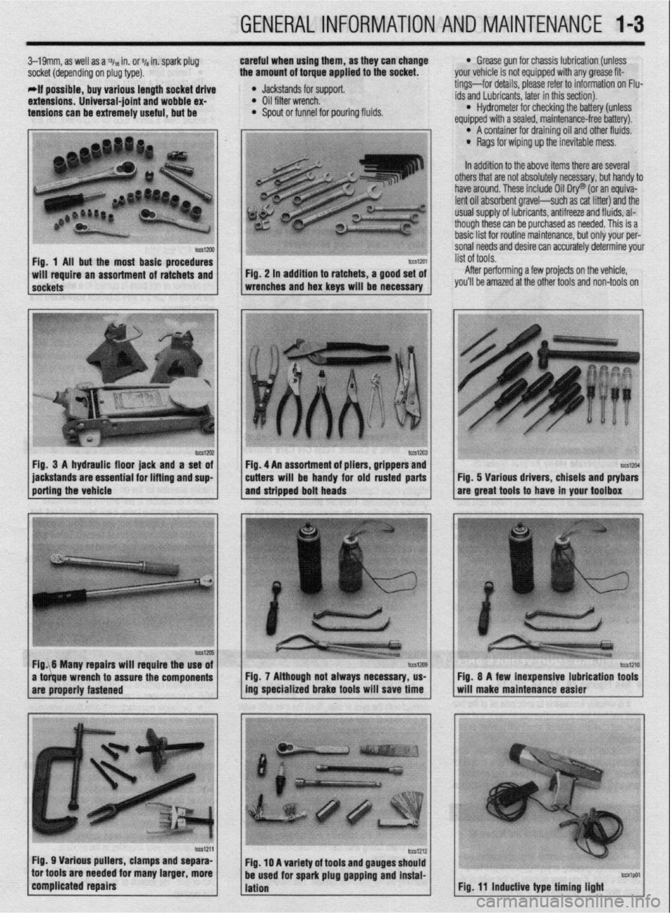
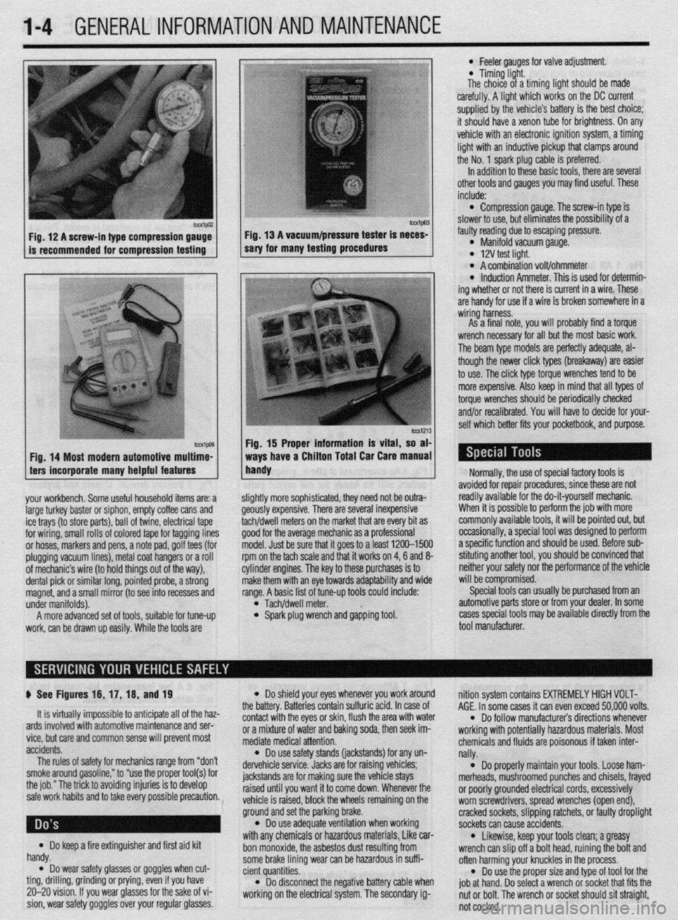
b See Figures 1 thru 15
Naturally, without the proper tools and equipment
it is impossible to properly service your vehicle. It
would also be virtually impossible
to catalog every
tool that you would need to perform all of the opera-
tions in this book. Of course, It would be unwise for
the amateur to rush out and buy an expensive set of
tools on the theory that he/she may need one or more
of them at some time, The best approach is to proceed slowly, gathering savings will
be far outweighed by frustration and
a good quality set of those tools that are used most mangled knuckles.
frequently Don’t be misled by the low cost of bargain Begin accumulating those tools that are used most
tools. It is far better to spend a little more for better frequently: those associated with routine maintenance
quality. Forged wrenches, 6 or 12-point sockets and and tune-up. In addition to the normal assortment of
fine tooth ratchets are by far preferable to their less screwdrivers and pliers, you should have the follow-
expensive counterparts. As any good mechanic can ing tools:
tell you, there are few worse experiences than trying
l Wrenches/sockets and combination open
to work on a vehicle with bad tools. Your monetary end/box end wrenches in sizes from %-% in. or
Page 3 of 408
GENERALINFORMATIONAND MAINTENANCE l-3
3-19mm, as well as a % in. or ~/a in. spark plug careful when using them, as they can change
socket (depending on plug type). the amount of torque applied to the socket.
-if possible, buy various length socket drive
l Jackstands for support.
extensions. Universal-joint and wobble ex- l Oil filter wrench.
tensions can be extremely useful, but be l Spout or funnel for pouring fluids.
l Grease gun for chassis lubrication (unless
your vehicle is not equipped with any grease fit-
tings-for details, please refer to information on Flu-
ids and Lubricants, later in this section).
l Hydrometer for checking the battery (unless
equiooed with a sealed, maintenance-free batten/).
In addition to the above items there are several O’ A container for draining oil and other fluids.
l Rags for wiping up the inevitable mess.
pi 1 others that are not absolutely necessary, but handy to
have around. These include Oil Dry@ (or an equiva-
lent oil absorbent gravel-such as cat litter) and the
usual SUDDIV of lubricants. antifreeze and fluids. al-
though the.& can be purchased as needed. This is a
basic list for routine maintenance, but only your per-
sonal needs and desire can accurately determine your
Fig. 1 Ail but the most basic procedures
After performing a few projects on the vehicle,
you’ll be amazed at the other tools and non-tools on
lWSl2U2 Fig, 3 A hydraulic floor jack and a set of
jackstands are essential for lifting and sup
porting the vehicle tm1204 Fig. 5 Various drivers, chisels and ptybars
are great tools to have in your toolbox
Fig. 7 Although not always necessary, us-
ing specialized brake tools will save time
Fig. 11 inductive type timing light
Page 4 of 408
I-4 GENERALINFORMATIONAND MAINTENANCE
Fig. 12 A screw-in type compression gauge- Fig. 13 A vacuum/pressure tester is neces-
is recommended for compression testing sary for many testing procedures
Fig. 14 Most modern automotive multime-
ters incorporate many helpful features
your workbench. Some useful household items are: a
large turkey baster or siphon, empty coffee cans and
ice trays (to store parts), ball of twine, electrical tape
for wiring, small rolls of colored tape for tagging lines
or hoses, markers and pens, a note pad, golf tees (for
plugging vacuum lines), metal coat hangers or a roll
of mechanic’s wire (to hold things out of the way),
dental pick or similar long, pointed probe, a strong
magnet, and a small mirror (to see into recesses and
under manifolds).
A more advanced set of tools, suitable for tune-up
work, can be drawn up easily. While the tools are
lmvl Fig. 15 Proper information is vital, so at
ways have a Chiiton Total Car Care manua
handy
l Feeler aauoes for valve adiustment
* Timing-light.
The choice of a timing fight should be made
carefully. A light which works on the DC current
supplied by the vehicle’s battery is the best choice;
it should have a xenon tube for brightness. On any
vehicle with an electronic ignition system, a timing
light with an inductive pickup that clamps around
the No. 1 spark plug cable is preferred.
In addition to these basic tools, there are several
other tools and gauges you may find useful. These
include:
l Compression gauge. The screw-in type is
slower to use, but eliminates the possibility of a
fauliy reading due to escaping pressure.
l Manifold vacuum gauge. l 12V test light. l A combination volt/ohmmeter l induction Ammeter. This is used for determin-
ing whether or not there is current in a wire. These
are handy for use if a wire is broken somewhere in a
wiring harness.
As a final note, vou will orobablv find a torque
wrench necessary for all but the most basic work.
The beam type models are perfectly adequate, al-
though the newer click types (breakaway) are easier
to use. The click type torque wrenches tend to be
more expensive. Also keep in mind that all types of
torque wrenches should be periodically checked
and/or recalibrated. You will have to decide for your-
self which better fits your pocketbook, and purpose.
ilightly more sophisticated, they need not be outra-
feously expensive. There are several inexpensive
achldwell meters on the market that are every bit as
Toad for the average mechanic as a professional
nodel. Just be sure that it goes to a least 1200-1500
pm on the tach scale and that it works on 4,6 and 8-
:ylinder engines. The key to these purchases is to
nake them with an eye towards adaptability and wide
ange. A basic list of tune-up tools could include:
l Tach/dwell meter. l Spark plug wrench and gapping tool. Normally, the use of special factory tools is
avoided for repair procedures, since these are not
readily available for the do-it-yourself mechanic.
When it is possible to perform the job with more
commonly available tools, it will be pointed out, but
occasionally, a special tool was designed to perform
a specific function and should be used. Before sub-
stituting another tool, you should be convinced that
neither your safety nor the performance of the vehicle
will be compromised.
Special tools can usually be purchased from an
automotive parts store or from your dealer. In some
cases special tools may be available directly from the
tool manufacturer.
p See Figures 16, 17, 16, and 19
It is virtually impossible to anticipate all of the haz-
ards involved with automotive maintenance and ser-
vice, but care and common sense will prevent most
accidents.
The rules of safety for mechanics range from “don’t
smoke around gasoline,” to “use the proper tool(s) for
the job.” The trick to avoiding injuries is to develop
safe work habits and to take every possible precaution.
Do keep a fire extinguisher and first aid kit
l handy.
Do wear safety glasses or goggles when cut- l ting, drilling, grinding or prying, even if you have
20-20 vision. If you wear glasses for the sake of vi-
sion, wear safety goggles over your regular glasses.
l Do shield your eyes whenever you work around
the battery. Batteries contain sulfuric acid. In case of
contact with the eyes or skin, flush the area with water
or a mixture of water and baking soda, then seek im-
mediate medical attention.
l Do use safety stands (jackstands) for any un-
dervehicle service. Jacks are for raising vehicles;
jackstands are for making sure the vehicle stays
raised until you want it to come down. Whenever the
vehicle is raised, block the wheels remaining on the
ground and set the parking brake.
l Do use adequate ventilation when working
with any chemicals or hazardous materials, Like car-
bon monoxide, the asbestos dust resulting from
some brake lining wear can be hazardous in suffi-
cient quantities.
l Do disconnect the negative battery cable when
working on the electrical system. The secondary ig- nition system contains EXTREMELY HIGH VOLT-
AGE. In some cases it can even exceed 50,000 volts.
l Do follow manufacturer’s directions whenever
working with potentially hazardous materials. Most
chemicals and fluids are poisonous if taken inter-
nally.
l Do properly maintain your tools. Loose ham-
merheads, mushroomed punches and chisels, frayed
or poorly grounded electrical cords, excessively
worn screwdrivers, spread wrenches (open end),
cracked sockets, slipping ratchets, or faulty droplight
sockets can cause accidents.
* Likewise, keep your tools clean; a greasy
wrench can slip off a bolt head, ruining the bolt and
often harming your knuckles in the process.
l Do use the proper size and type of tool for the
job at hand. Do select a wrench or socket that fits the
nut or bolt. The wrench or socket should sit straight,
not cocked.
Page 10 of 408
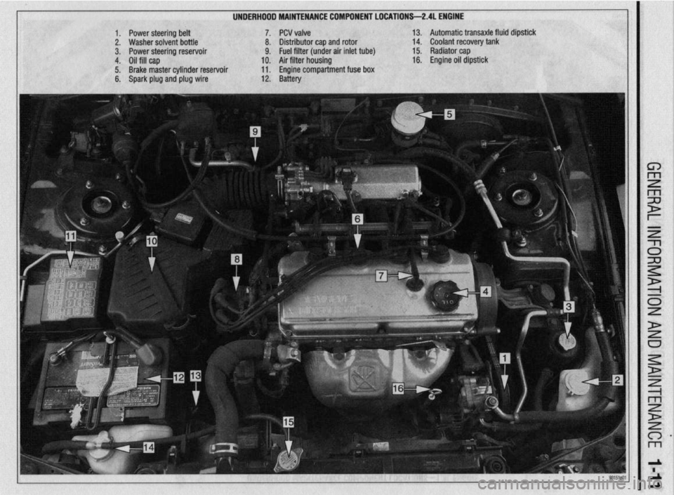
UNDERHDDD MAINTENANCE COMPONENT LOCATIONS-2AL ENGINE
II
1. Power steering belt 7. PCV valve
2. Washer solvent bottle 8. Distributor cap and rotor
3. Power steering reservoir 9. Fuel filter (under air inlet tube)
4. Oil fill cap 10. Air filter housing
5. Brake master cylinder reservoir 11. Engine compartment fuse box
6. Spark plug and plug wire 12. Battery 13. Automatic transaxle fluid dipstick
14. Coolant recovery tank
15. Radiator cap
16. Engine oil dipstick
Page 11 of 408
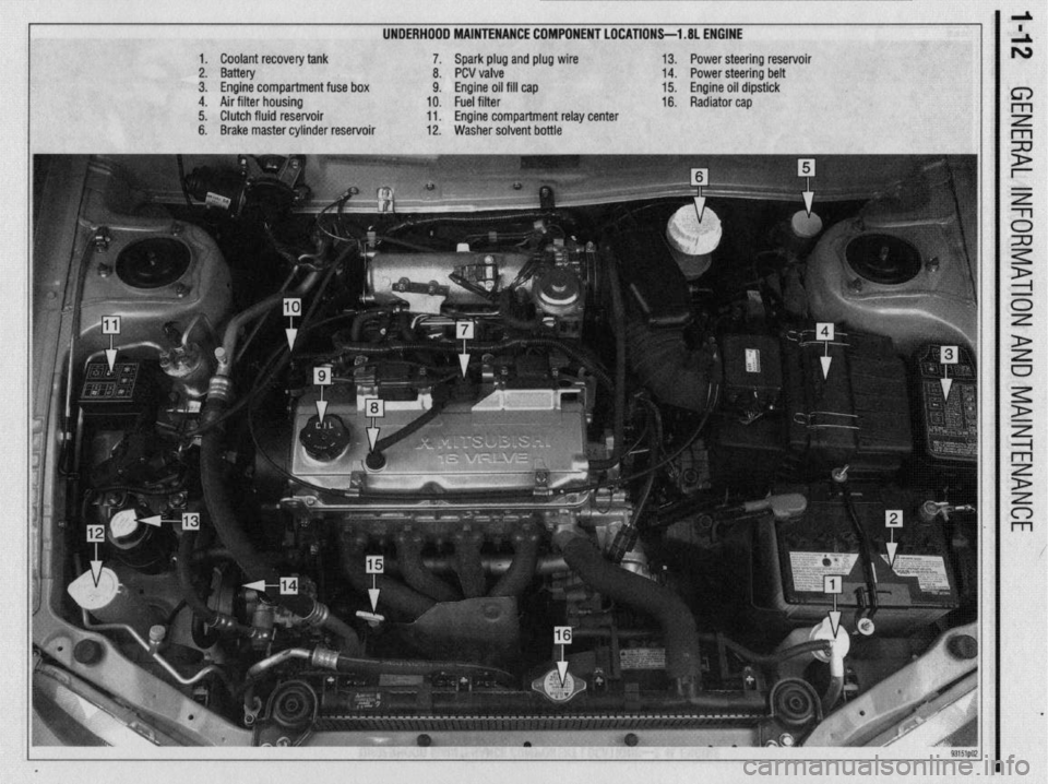
UNDERHOOD MAINTENANCE COMPONENT LOCATIONS-l .8L ENGINE
1. Coolant recovery tank
2. Battery
3. Engine compartment fuse box
4. Air filter housing
5. Clutch fluid reservoir
6. Brake master cylinder reservoir 7. Spark plug and plug wire
8. PCV valve
9. Engine oil fill cap
10. Fuel filter
11. Engine compartment relay center
12. Washer solvent bottle 13. Power steering reservoir
14. Power steering belt
15. Engine oil dipstick
16. Radiator cap
Page 32 of 408
GENERALINFORMATIONAND MAINTENANC-E 1133
Used fluids such as engine oil, transaxle fluid, an-
tifreeze and brake fluid are hazardous wastes and
must be disposed of properly. Before draining any
fluids, consult with your local authorities; in many ar-
eas, waste oil, antifreeze, etc. is being accepted as a
part of recycling programs. A number of service sta-
tions and auto parts stores are also accepting waste
fluids for recycling.
Be sure of the recycling center’s policies before
draining any fluids, as many will not accept different
fluids that have been mixed together.
ENGINE OIL
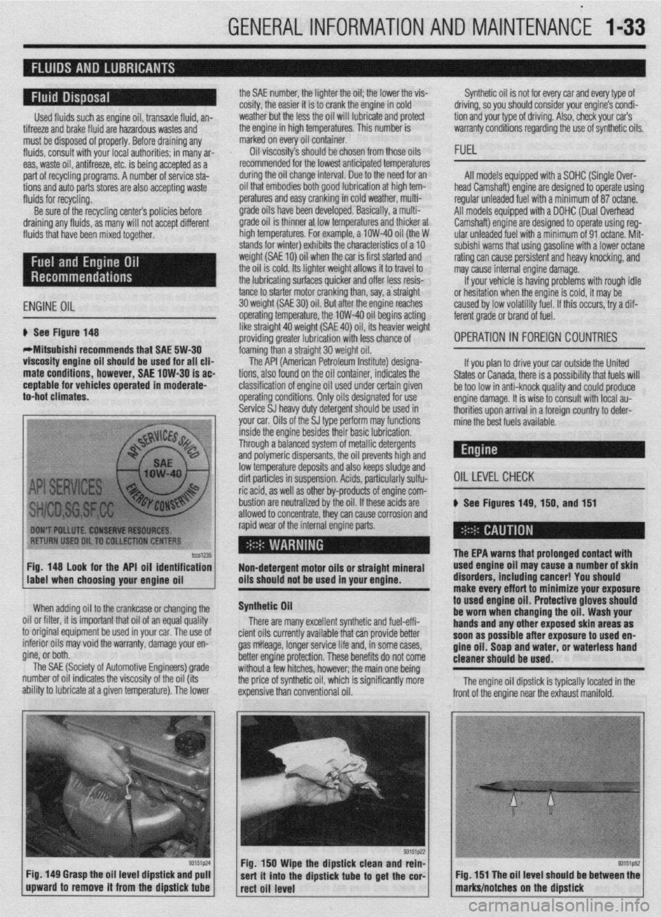
6 See Figure 148
WMitsubishi recommends that SAE 5W-30
viscosity engine oil should be used for all clia
mate conditions, however, SAE low-30 is ac
ceptable for vehicles operated in moderate-
to-hot climates. the SAE number, the lighter the oil; the lower the vis-
cosity, the easier it is to crank the engine in cold
weather but the less the oil will lubricate and protect
the engine in high temperatures. This number is
marked on every oil container.
Oil viscosity’s should be chosen from those oils
recommended for the lowest anticipated temperatures
during the oil change interval. Due to the need for an
oil that embodies both good lubrication at high tem-
peratures and easy cranking in cold weather, multi-
grade oils have been developed. Basically, a multi-
grade oil is thinner at low temperatures and thicker at
high temperatures. For example, a low-40 oil (the W
stands for winter) exhibits the characteristics of a 10
weight (SAE 10) oil when the car is first started and
the oil is cold. Its lighter weight allows it to travel to
the lubricating surfaces quicker and offer less resis-
tance to starter motor cranking than, say, a straight
30 weight (SAE 30) oil. But atier the ensine reaches
operating temperature, the low-40 oil begins acting
like straight 40 weight (SAE 40) oil, its heavier weight
providing greater lubrication with less chance of
foaming than a straight 30 weight oil. Synthetic oil is not for every car and every type of
driving, so you should consider your engine’s condi-
tion and your type of driving. Also, check your car’s
warranty conditions regarding the use of synthetic oils.
FUEL
All models equipped with a SOHC (Single Over-
head Camshaft) engine are designed to operate using
regular unleaded fuel with a minimum of 87 octane.
All models equipped with a DOHC (Dual Overhead
Camshaft) engine are designed to operate using reg-
ular unleaded fuel with a minimum of 91 octane. Mit-
subishi warns that using gasoline with a lower octane
rating can cause persistent and heavy knocking, and
may cause internal engine damage.
If your vehicle is having problems with rough idle
or hesitation when the enoine is cold, it mav be
caused by low volatility fuel. If this occurs, iry a dif-
ferent grade or brand of fuel.
'OPERATION 1~ FOREIGN COUNTRIES
lccS1235 Fig. 148 look for the API oil identification
Non-detergent motor oils or straight mineral
label when choosing your enaine oil oils should not be used in your engine.
When adding oil to the crankcase or changing the
0 Nil or filter, it is important that oil of an equal quality
I original equipment be used in your car. The use of
. tc mtenor 011s may void the warranty, damage your en-
gine, or both. __
The SAE (Society of Automotive Engineers) grade
number of oil indicates the viscosity of the oil (its
ability to lubricate at a given temperature). The lower
Fig. 149 Grasp the oil level dipstick and pull
upward to remove it from the dipstick
tube
The API (American Petroleum Institute) designa-
tions, also found on the oil container, indicates the
classification of engine oil used under certain given
operating conditions. Only oils designated for use
Service SJ heavy duty detergent should be used in
your car. Oils of the SJ type perform may functions If you plan to drive your car outside the United
States or Canada, there is a possibility that fuels will
be too low in anti-knock quality and could produce
engine damage. It is wise to consult with local au-
thorities upon arrival in a foreign country to deter-
mine the best fuels available.
inside the engine besides their basic lubrication.
Through a balanced system of metallic detergents
and polymeric dispersants, the oil prevents high and
low temperature deposits and also keeps sludge and
dirt particles in suspension. Acids, particularly sulfu-
OILLEVELCHECK ric acid, as well as other by-products of engine com-
bustion are neutralized by the oil. If these acids are
# See Figures 149, 150, and 151
allowed to concentrate, thev can cause corrosion and
rapid wear of the internal engine parts.
Synthetic Oil
There are many excellent synthetic and fuel-effi-
cient oils currently available that can provide better
gas mileage, longer service life and, in some cases,
better engine protection. These benefits do not come
without a few hitches, however; the main one being
the price of synthetic oil, which is significantly more
expensive than conventional oil.
.
The EPA warns that urolonoed contact with used engine oil ma; cause-a number of skin
disorders, including cancer! You should
make every effort to minimize your exposure
to
used engine oil. Protective gloves should
be worn when changing the oil. Wash your
hands and any other exposed skin areas as
soon as possible after exposure to used en-
gine oil. Soap and water, or waterless hand
cleaner should be used.
Fig. 150 Wipe the dipstick clean and rein-
sert it into the dipstick
tube to get the cor-
rect oil level The engine oil dipstick is typically located in the
Fig. 151 The oil level should be between the
marks/notches on the dipstick
Page 35 of 408
.
l-36 GENERALINFORMATIONAND MAINTENANCE
Install the drain plug and tighten to 22 ft. Ibs.
(304Nm)
5. Refill the transaxle to the proper level, as
shown in the Capacities chart, with the appropriate
fluid. The oil level should be at the bottom of the oil
filler hole. I
6. When the oil reaches the orooer level, install
the filler plug and tighten to 22 ft. Ibs. (30 Nm).
FLUID RECOMMENDATIONS
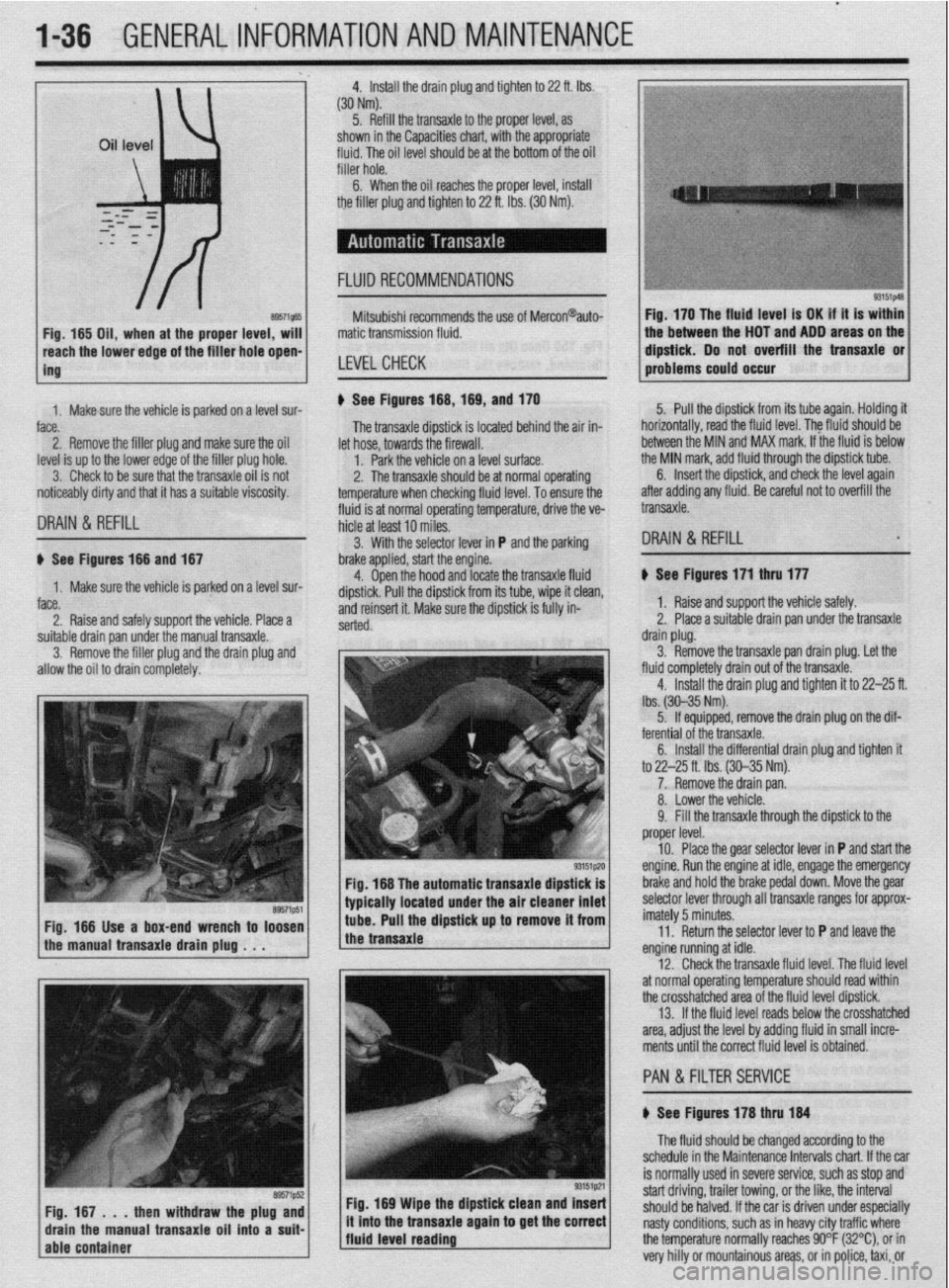
8957i565 Fig, 165 Oil, when at the proper level, will
reach the lower edge of tC=+ frfr*r u*rn -non-
ing Mitsubishi recommends the use of Mercon@auto-
matic transmission fluid.
LEVELCHECK
Fig. 170 The fluid level is OK if it is within
the between the HOT and ADD areas on the
&&i& Do not overfill the transaxle or
-.*".."... -- .*"- problems could o ccur
1. Makesure the vehicle is oarked on a level sur-
face.
2. Remove the filler plug and make sure the oil
level is up to the lower edge of the filler plug hole.
3. Check to be sure that the transaxle oil is not
noticeably dirty and that it has a suitable viscosity. u See Figures 168,169, and 170
fluid is at normal operating temperature, drive the ve- The transaxle dipstick is located behind the air in-
hicle at least 10 miles. let hose, towards the firewall.
1. Park the vehicle on a level surface.
2. The transaxle should be at normal operating
temperature when checking fluid level. To ensure the 5. Pull the dipstick from its tube again. Holding it
horizontally, road the fluid level. The fkrid should be
between the MIN and MAX mark. If the fluid is below
the MIN mark, add fluid through the dipstick tube.
DRAIN & REFILL
6. Insert the dipstick, and check the level again
after adding any fluid. Be careful not to overfill the
transaxle.
3. With the selector lever in P and the parking
DRAIN & REFILL u See Figures 166 and 167
1. Make sure the vehicle is parked on a level sur-
face.
2. Raise and safely support the vehicle. Place a brake applied, start the engine.
4. Open the hood and locate the transaxle fluid
dipstick. Pull the dipstick from its tube, wipe it clean,
and reinsert it. Make sure the dipstick is fully in-
serted.
suitable drain pan under the manual transaxle.
3. Remove the filler plug and the drain plug and
allow the oil to drain completely.
Fig. 166 The automatic transaxle dipstick is
typically located under the air cleaner inlet
Fig. 166 Use a box-end wrench to loosen
the manual transaxle drain plug . . . tube. Pull the dipstick up to remove it from
the transaxle
Fig. 169 Wipe the dipstick clean and Insert
/fluid level reading ., it mto the transaxle agam to get the correct
j The fluid should be changed according to the
schedule in the Maintenance Intervals chart. If the car
is normally used in severe service, such as stop and
start driving, trailer towing, or the like, the interval
should be halved. If the car is driven under especially
nasty conditions, such as in heavy city traffic where
the temperature normally reaches 90°F (32%), or in
very hilly or mountainous areas, or in police, taxi, or b See Figures 171 thru 177
1. Raise and support the vehicle safely.
2. Place a suitable drain pan under the transaxle
drain plug.
3. Remove the transaxle pan drain plug. Let the
fluid completely drain out of the transaxle.
4. Install the drain plug and tighten it to 22-25 ft.
lbs. (30-35 Nm).
5. If equipped, remove the drain plug on the dif-
ferential of the transaxle.
6. Install the differential drain plug and tighten ft
to 22-25 ft. Ibs. (30-35 Nm).
7. Remove the drain pan.
8. Lower the vehicle.
9. Fill the transaxle through the dipstick to the
proper level.
10. Place the gear selector lever in P and start the
engine. Run the engine at idle, engage the emergency
brake and hold the brake pedal down. Move the gear
selector lever through all transaxle ranges for approx-
imately 5 minutes.
11. Return the selector lever to P and leave the
engine running at idle.
12. Check the transaxle fluid level. The fluid level
at normal operating temperature should read within
the crosshatched area of the fluid level dipstick.
13. If the fluid level reads below the crosshatched
area, adjust the level by adding fluid in small incre-
ments until the correct fluid level is obtained.
PAN &FILTER SERVICE
b See Figures 178 thru 184
Page 37 of 408

t
1-38 GENERALINFORMATIONAND MAINTENANCE
11 I Add the recommended automatic transaxle
fluid to the transaxle through the dipstick tube. You
will need a long necked funnel, or a funnel and tube
to do this. A quick check of the capacities chart later
in this Section will reveal the capacity of the transaxle
in your vehicle. On a first fill after removing the pan
and filter, this number should be cut into a ‘hand
checked on the dipstick before refilling.
12. With the transaxle in P, put on the parking
brake, block the front wheels, start the engine and let
it idle. DO NOT RACE THE ENGINE. DO NOT MOVE
THE LEVER THROUGH ITS RANGES.
13. With the lever in Park, check the fluid level. If
it’s OK, take the car out for a short drive, park on a
level surface, and check the level again, as outlined
earlier in this section. Add more fluid if necessary. Be
careful not to overfill, which will cause foaming and
w fluid loss. n of the transfer case filler
3. Remove the filler and the drain plug and allow
the oil to drain into the drain pan.
4. After the fluid has drained completely, install
the drain plug and tighten to 24 ft. Ibs. (32 Nm).
5. Refill the transfer case to the proper level with
Fig. 184 . . .
the transaxle case before in-
stalling the gasket
and pan onto the case FLUID RECOMMENDATIONS Hypoid gear oil SAE 75W-85W/75W-9OW conform-
ing to API specifications GL-4 or higher. The oil level
-‘-,*I’ -nnnh +‘* “%om edge of the oil filler hole.
nxfer raw filler nlm and tinhtm When adding fluid or refilling the transfer case,
use Hypoid gear oil SAE 75W-85W or 75W-9OW
conforming to API specifications 61-4 or higher.
LEVELCHECK 6. Install the tra .._._. ____ .._. T.-J _.._ .lJ . .._..
to 24 ft. lbs. (32 Nm).
7. Carefully lower the vehicle.
u See Figure 185
, 1 FLUID RECOMMENDATIONS
delivery service, the fluid should be changed accord-
ing to the severe service schedule.
The fluid must be hot before it is drained; a 20 u See Figure 187
Since fluid viscosity range may
vary depending on
specific temperature range of operation, please refer
~~
tne transaxle case.
You’ll be very sorry later if you do. bottom edge of the transfer case filler 1 1 Fig. 187 Rear axle lubricant application I
*If the drained fluld is discolored (brown or
1 plug hole chart black), thick, or pmmll~ hmmt nnrinmm I transaxle trouble .llln3llU ““III., url,““P s, probably due to overheat-
,r..rr,rA “#.a.- rrdr
trig, should be susp~~lr;u. lvUl vLlr J
transaxle should be inspected by a reliable
transaxle specialist to determine the prob-
lem.
5. Remove the pan and gasket.
6. Clean the pan with solvent and allow it to air
dry. If you use a rag to wipe out the pan, you risk
leaving bits of lint behind, which will clog the dinky
hydraulic passages in the bansaxle.
7. Remove the filter retaining bolts and remove
the filter from the valve bodv. lnsoect each component for leaking. Check the oil
he filler plug. If the oil is contami-
ry to replace it with new oil.
if% nn IPVPI z11rf2r~
level by removing t
nated, it is necessa
1. Park the vehi,., -.. ,-.“, __. ,“-_.
2. Remove the filler plug and make sure the oil
level reaches the lower edge of the filler plug hole.
3. Check to be sure that the oil is not noticeably
dirty and that it has the proper viscosity.
4. If necessary, add oil through the filler hole until
is runs out of the hole. to the accompanying chart for the proper fluid for
your vehicle.
LEVEL CHECK
1. Make sure the vehicle is parked on level
ground.
2. Remove the oil fill plug to check the oil level.
3. The oil level is sufficient if it reaches the lower
portion of the filler plug hole. If the fluid is low, add
as required through the filler plug.
To install: .
8. Install a new filter, then install the retaining
bolts and tighten them to 5 ft. Ibs. (7 Nm).
9. Position the gasket on the pan, then install
the pan. Tighten the bolts evenly and in rotation to
8-9ft. Ibs. (10-12 Nm.). Do not overtighten.
IO. Lower the vehicle. DRAIN & REFILL
I8 DRAIN & REFILL
u See Figure 188 ) See Figure- 14
1. Raise and safely support the vehicle, for access
to the transfer case.
2. Place a suitable drain pan under the transfer
case fluid drain plug. 1. Position the vehicle on a flat surface or raise
and safely support the vehicle in a level position.
2. Place a suitable drain pan under the rear axle.
Page 40 of 408
.
GENERALINFORMATIONAND MAINTENANCE l-41
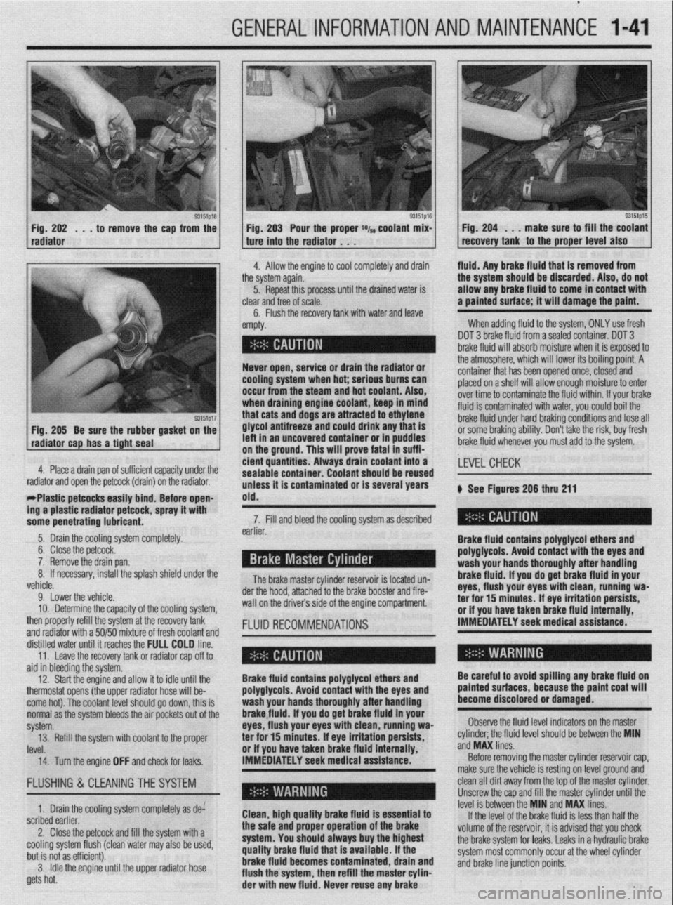
93151p18 Fig. 202 . , . to remove the cap from the
radiator
93151p17 Fig. 205 Be sure the rubber gasket on the
radiator cap has a tight seal e Fig. 203 Pour the proper *I~ coolant mix- 1 Fig. 204 . . . make sure to fill the coolant
recovery tank to the proper level also ture into the radiator . . .
.I
4. Allow the engine to cool completely and drain fluid. Any brake fluid that is removed from
ie system again.
5. Repeat this processuntil the drained water is
lear
and free of scale.
6. Flush the recovery tank with water and leave ’
mpty. the system should be discarded. Also, do not
allow any brake fluid to come in contact with
a painted surface; it will damage the paint.
When adding fluid to the system, ONLY use fresh
DOT 3 brake fluid from a sealed container. DOT 3
brake fluid will absorb moisture when it is exposed to
.a . . . , .*a. . . * .*. . .
- Never open, service or drain the radiator or
cooling system when hot; serious bums can
occur from the steam and hot coolant. Also,
when draining engine coolant, keep In mind
that cats and dogs are attracted to ethylene
glycol antifreeze and could drink any that is
left in an uncovered container or in puddles
on the ground. This will prove fatal in suffi-
4. Place a drain pan of suff i ’ 1 . . . ..I .I. 1,~ cient quantities. Always tne atmospnere, wnrcn wnr rower 1r.s oourng pomr. A
container that has been opened once, closed and
placed on a shelf will allow enough moisture to enter
over time to contaminate the fluid within. If your brake
fluid is contaminated with water, you could boil the
brake fluid under hard braking conditions and lose all
or some braking ability. Don’t take the risk, buy fresh
brake fluid whenever you must add to the system.
crenr capacrry unaer me
drain) on the radiator.
rrrasuc perwcss easuy bind; Before open-
ing a plastic radiator petcock, spray it with
some penetrating lubricant. drain coolant into a
earner. sealable container. Coolant should be reused
unless it is contaminated or is several years
old.
The brake master cylinder ~a~~~~r,~~ :A I~nnL.4 n-n 7. Fill and bleed the cooling system as described
Brake fluid contains polyglycol ethers and
polyglycols. Avoid contact with the eyes and ,LEVEL CHECK
wash your hands thoroughly after handling
brake fluid. If vou do oet brake fluid in vour
eyes, flush your eyeswith clean, runniug wa-
a-.. ‘Y-- ar -l-..n-- II -.._ I____ k See Figures 206 thru 211
.a-11-- - __-PA._ radiator and open the petcock (
- w&1--x3_ --mm.._..- . . ..-I...
5. Drain the cooling system completely.
6. Close the petcock.
7. Remove the drain pan.
If necessary, install the splash shield under the 8.
L.-l
venicie.
9. Lower the vehicle.
10. Determine the capacity of the cooling system,
then properly refill the system at the recovery tank
and radiator with a 50/50 mixture of fresh coolant and
fKm”“ll 15 IUMLC” “II- brake booster and fire- der the hood, attached to the
wall on the drivers side of the engine compartment.
FLUID RECOMMENDATIONS rer mr 13 mmures. IT eye irriIauon persim, or if you have taken brake fluid internally,
IMMEDIATELY seek medical assistance.
ala in oreerring me sysrem.
12. Start the engine and allow it to idle until the
thermostat opens (the upper radiator hose will be-
come hot). The coolant level should go down, this is
normal as the system bleeds the air pockets out of the
svstem.
IRVf!l ._._. 14. Turn the engine OFF and check for leaks. IMMEDIATELY seek medical assistance.” Brake fluid contains polyglycol ethers and
polyglycols. Avoid contact with the eyes and
wash your hands thoroughly after handling
brakefluid. If you do get brake fluid in your
eyes, flush your eyes with clean, running wa-
or if vou have taken brake fluid internallv.
Before removing the master cylinder reservoir cap,
make sure the vehicle is resting on level ground and Be careful to avoid spilling any brake fluid on
painted surfaces, because the paint coat will
become discolored or damaged.
Observe the fluid level indicators on the master
._ ._ __
‘eve1 should be between the MIN
ano
ivw unes. 13. Refill the system with coolant to the proper ter for 15 minutes; If eye irritation persists, cylinder; the tluld II
..J ..I” I....
FLUSHING & CLEANINGTHE SYSTEM
1. Drain the cooling system completely as de:
scribed earlier.
2. Close the petcock and fill the system with a
cooling system flush (clean water may also be used,
but is not as efficient).
3. Idle the engine until the upper radiator hose
gets hot. Clean, high quality brake fluid is essential to
the safe and proper operation of the brake
system. You should always buy the highest
quality brake fluid that is available. If the
brake fluid becomes contaminated, drain and
flush the system, then refill the master cylin-
der with new fluid. Never reuse any brake clean all dirt away from the top of the master cylinder.
Unscrew the cap and fill the master cylinder until the
level is between the MIN and MAX lines.
If the level of the brake fluid is less than half the
volume of the reservoir, it is advised that you check
the brake system for leaks. Leaks in a hydraulic brake
system most commonly occur at the wheel cylinder
and brake line junction points.
Page 41 of 408
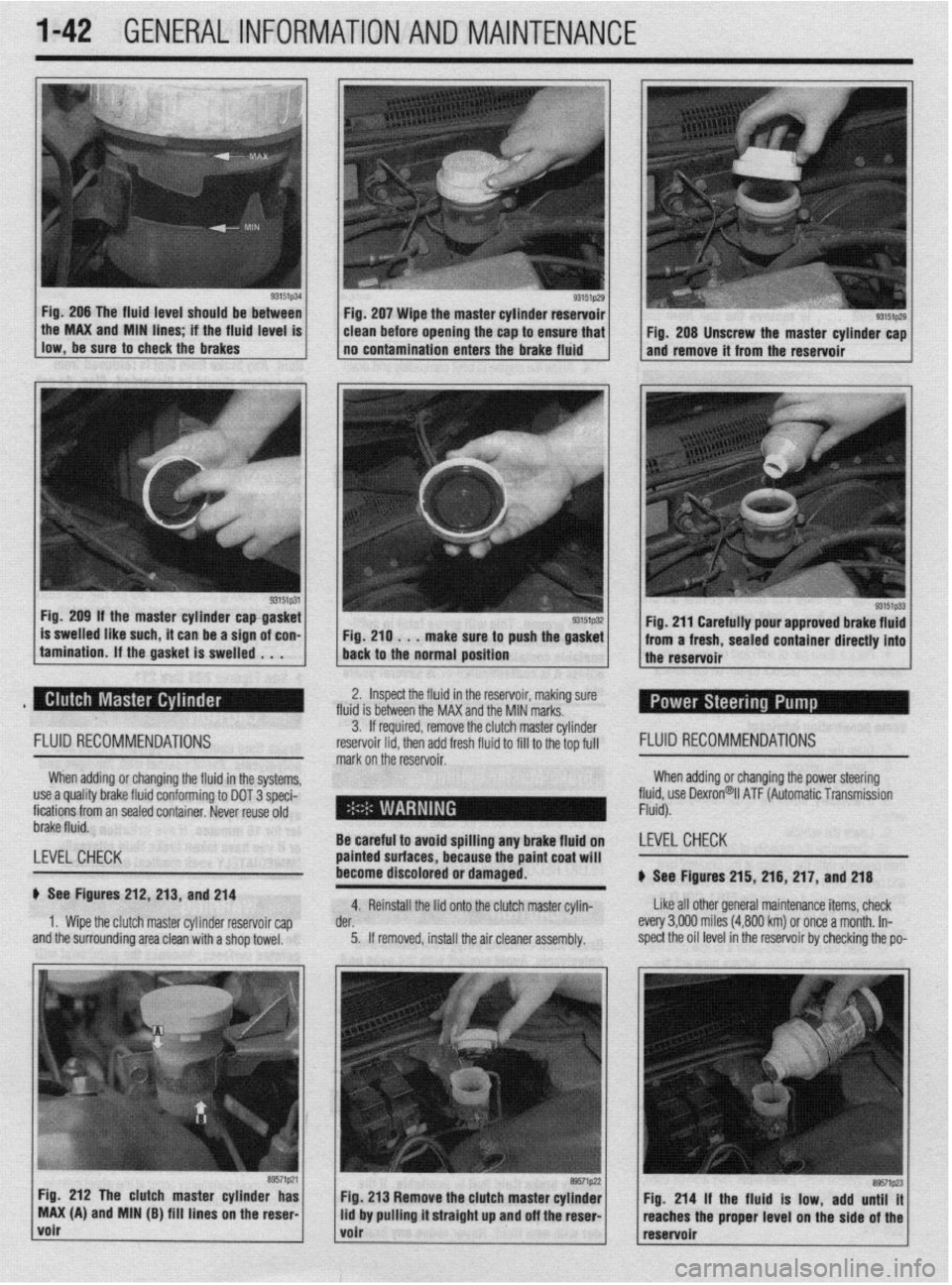
1-42 GENERAL~INFORMATION AND MAINTENANCE
Fig. 206 The fluid level should be between
llow,be*“retoch~ckiebrake~ . the MAX and MIN hnes if the fhud level IS
93151p31 Fig. 209 If the master cylinder capgasket
is swelled like such, it can be a sign of con-
tamination. If the gasket is swelled . . . Fig. 207 Wipe the master cylinder reservoir
clean before opening the cap to ensure that
no contamination enters the brake fluid
Fig. 210 . . .
make sure to push the gasket
back to the normal position
93151p29 I Fig. 208 Unscrew the master cylinder cap
and remove it from the reservoir
Fig. 211 Carefully pour approved brake fluid
from a fresh, sealed container directly into
the reservoir
2. Inspect the fluid in the reservoir, making sure
fluid is between the MAX and the MIN marks.
FLUID RECOMMENDATIONS
When adding or changing the fluid in the systems,
use a quality brake fluid conforming to DOT 3 speci-
fications from an sealed container. Never reuse old
brake fluid.
LEVEL CHECK
b See Figures 212, 213, and 214
1. Wipe the clutch master cylinder reservoir cap
and the surrounding area clean with a shop towel. 3. If required, remove the clut ch master cylinder
reservoir lid. then add fresh fluid I FLUID RECOMMENDATIONS
mark on the’reservoir. to fill to the top full
When adding or changing the power steering
fll$,“” Dexron@il ATF (Automatic Transmission
-
- .
Be careful to avoid sf Billing any brake fluid on LEVELCHECK
painted surfaces, bet
:ause the paint coat will
become discolored or damaged.
b See Figures 215, 216, 217, and 218
4. Reinstall the lid onto the clutch master cylin- Like all other general maintenance items, check
der. every 3,OOfl miles (4,800 km) or once a month. In-
5. If removed, install the air cleaner assembly. spect the oil level in the reservoir by checking the po-
Fig. 212 The clutch master cylinder has
MAX (A) and MIN (B) fill lines on the reser
volr