air bleeding MITSUBISHI DIAMANTE 1900 Repair Manual
[x] Cancel search | Manufacturer: MITSUBISHI, Model Year: 1900, Model line: DIAMANTE, Model: MITSUBISHI DIAMANTE 1900Pages: 408, PDF Size: 71.03 MB
Page 31 of 408
.
1-32 GENERALINFORMATIONAND MAINTENANCE
CONDITION
EFFECT
CAUSE
CORRECTION UNDER-INFLATION
EXCESSIVE SPEED’ WORN OR OUT-
OF-ALIGNMENT
ADJUST PRESSURE TO
SPECIFICATIONS WHEN
TIRES ARE COOL
ROTATE TIRES
/ BALANCE WHEELS INSPECT SUSPENSION
HAVE TIRE INSPECTED FOR FURTHER USE.
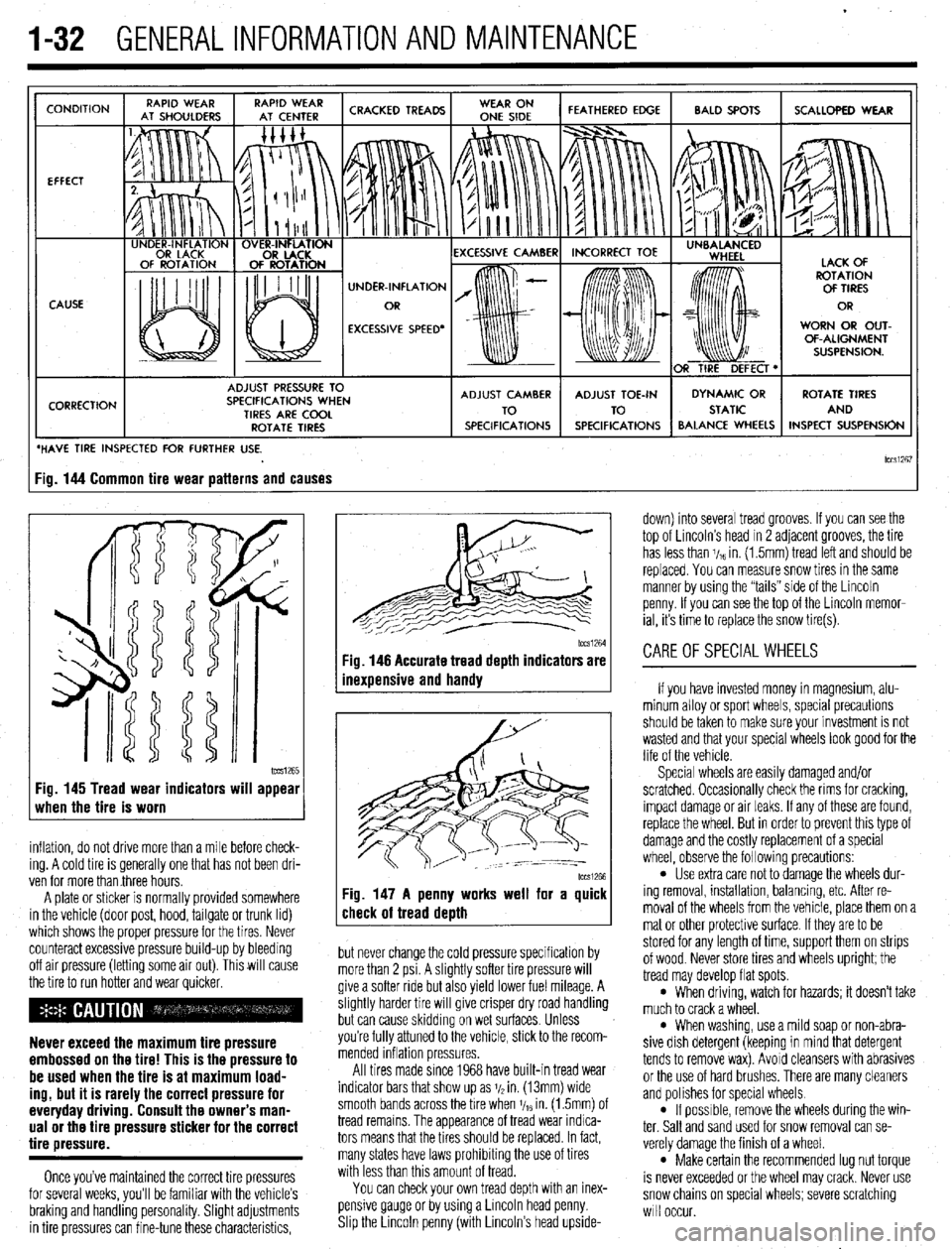
lCCSi267 ig. 144 Common tire wear patterns and causes
1~~~1265 Fig. 145 Tread wear indicators will appear
when the tire is worn
inflation, do not drive more than a mile before check-
ing. A cold tire is generally one that has not been dri-
ven for more than three hours.
A plate or sticker is normally provided somewhere
in the vehicle (door post, hood, tailgate or trunk lid)
which shows the proper pressure for the tires. Never
counteract excessive pressure build-up by bleeding
off air pressure (letting some air out). This will cause
the tire to run hotter and wear quicker.
Never exceed the maximum tire pressure
embossed on the tire! This is the pressure to
be used when the tire is at maximum load-
ing, but it is rarely the correct pressure for
everyday driving. Consult the owner’s man-
ual or the tire pressure sticker for the correct
tire pressure.
Once you’ve maintained the correct tire pressures
for several weeks, you’ll be familiar with the vehicle’s
braking and handling personality. Slight adjustments
in tire pressures can fine-tune these characteristics,
1~~~1264 Fig. 146 Accurate tread depth indicators are
inexuensive and handv
Fig. 147 A penny works well for a quick
check of tread death
but never change the cold pressure specification by
more than 2 psi. A slightly softer tire pressure will
give a softer ride but also yield lower fuel mileage. A
slightly harder tire will give crisper dry road handling
but can cause skidding on wet surfaces. Unless
you’re fully attuned to the vehicle, stick to the recom-
mended inflation pressures.
All tires made since 1968 have built-in tread wear
indicator bars that show up as j/2 in. (13mm) wide
smooth bands across the bre when V,~ in. (1.5mm) of
tread remains. The appearance of tread wear indica-
tors means that the tires should be replaced. In fact,
many states have laws prohibiting the use of tires
with less than this amount of tread.
You can check your own tread depth with an inex-
pensive gauge or by using a Lincoln head penny.
Shp the Lrncoln penny (with Lincoln’s head upside- down) into several tread grooves. If you can see the
top of Lincoln’s head in 2 adjacent grooves, the tire
has less than V,~ in. (1.5mm) tread left and should be
replaced. You can measure snow tires in the same
manner by using the “tails” side of the Lincoln
penny. If you can see the top of the Lincoln memor-
ial, its time to replace the snow tire(s).
CAREOFSPECIALWHEELS
If you have invested money in magnesium, alu-
minum alloy or sport wheels, special precautions
should be taken to make sure your investment is not
wasted and that your special wheels look good for the
life of the vehicle.
Special wheels are easily damaged and/or
scratched. Occasionally check the rims for cracking,
impact damage or air leaks. If any of these are found,
replace the wheel. But in order to prevent this type of
damage and the costly replacement of a special
wheel, observe the following precautions:
l Use extra care not to damage the wheels dur-
ing removal, installation, balancing, etc. After re-
moval of the wheels from the vehicle, place them on a
mat or other protective surface. If they are to be
stored for any length of time, support them on strips
of wood. Never store tires and wheels upright; the
tread may develop flat spots.
l When driving, watch for hazards; it doesn’t take
much to crack a wheel.
l When washing, use a mild soap or non-abra-
sive dish detergent (keeping in mind that detergent
tends to remove wax). Avoid cleansers with abrasives
or the use of hard brushes. There are many cleaners
and polishes for special wheels.
l If possrble, remove the wheels during the win-
ter. Salt and sand used for snow removal can se-
verely damage the finish of a wheel.
l Make certain the recommended lug nut torque
is never exceeded or the wheel may crack. Never use
snow chains on special wheels; severe scratching
will occur.
Page 288 of 408
DRIVETRAIN 7-9
*When adjusting the clutch pedal height or
the clutch pedal clevis pin play, be careful
not to push the pushrod toward the master
cylinder.
d. Check that when the clutch pedal is de-
pressed all the way, the interlock switch switches
over from ON to OFF.
ADJUSTMENT
# See Figure 42
*The following adjustment is for the cable
actuated clutch system on the Mirage. The
Hydraulic systems on all other models are
self-adjusting.
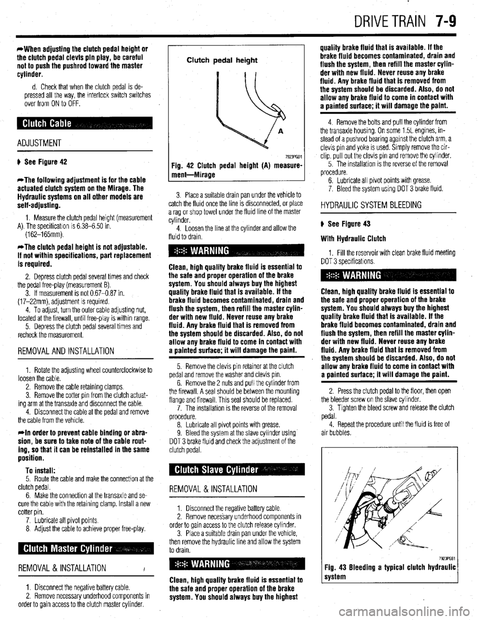
1. Measure the clutch pedal height (measurement
A). The specificatron is 6.38-6.50 in.
(162-165mm).
*The clutch pedal height is not adjustable.
If not within specifications, part replacement
is required.
2. Depress clutch pedal several times and check
the pedal free-play (measurement B).
3. If measurement is not 0.67-0.87 in.
(17-22mm), adjustment is required.
4. To adjust, turn the outer cable adjusting nut,
located at the firewall, until free-play is within range.
5. Depress the clutch pedal several times and
recheck the measurement.
REMOVALANDINSTALLATION
1. Rotate the adjusting wheel counterclockwise to
loosen the cable.
2. Remove the cable retaining clamps.
3. Remove the cotter pin from the clutch actuat-
ing arm at the transaxle and disconnect the cable.
4. Disconnect the cable at the pedal and remove
the cable from the vehicle.
rln order to prevent cable binding or abra-
sion, be sure to take note of the cable rout-
ing, so that it can be reinstalled in the same
position.
To install:
5. Route the cable and make the connection at the
clutch pedal.
6. Make the connection at the transaxle and se-
cure the cable with the retaining clamp. Install a new
cotter pin.
7. Lubricate all pivot points.
8 Adjust the cable to achieve proper free-play.
REMOVAL &INSTALLATION
I
1. Disconnect the negative battery cable.
2. Remove necessary underhood components in
order to gain access to the clutch master cylinder.
Clutch pedal height
Fig. 42 Clutch pedal height (A) measure-
ment-Mirage
7923PGDl
3. Place a suitable drain pan under the vehicle to
catch the fluid once the line IS drsconnected, or place
a rag or shop towel under the fluid line of the master
cylinder.
4. Loosen the line at the cylinder and allow the
fluid to drain.
Clean, high quality brake fluid is essential to
the safe and proper operation of the brake
system. You should always buy the highest
quality brake fluid that is available. If the
brake fluid becomes contaminated, drain and
flush the system, then refill the master cylin-
der with new fluid. Never reuse any brake
fluid. Any brake fluid that is removed from
the system should be discarded. Also, do not
allow any brake fluid to come in contact with
a oainted surface; it will damage the paint.
5. Remove the clevis pin retainer at the clutch
pedal and remove the washer and clevis pm.
6. Remove the 2 nuts and pull the cylinder from
the firewall. A seal should be between the mounting
flange and firewall. This seal should be replaced.
7. The installation is the reverse of the removal
procedure.
8. Lubricate all pivot points with grease.
9. Bleed the system at the slave cylinder using
DOT 3 brake fluid and check the adjustment of the
clutch pedal.
REMOVAL &INSTALLATION
1. Disconnect the negative battery cable
2. Remove necessary underhood components in
order to gain access to the clutch release cylinder.
3. Place a suitable drain pan under the vehicle,
then remove the hydraulic line and allow the system
to drain.
Clean, high quality brake fluid is essential to
the safe and proper operation of the brake
system. You should always buy the highest quality brake fluid that is available. If the
brake fluid becomes contaminated, drain and
flush the system, then refill the master cylin-
der with new fluid. Never reuse any brake
fluid. Any brake fluid that is removed from
the system should be discarded. Also, do not
allow any brake fluid to come in contact with
a uainted surface; it will damage the paint.
4. Remove the bolts and pull the cylinder from
the transaxle housing. On some 1.5L engines, in-
stead of a pushrod bearing against the clutch arm, a
clevis pin and yoke is used. Simply remove the cir-
clip, pull out the clevis pin and remove the cylinder.
5. The installation IS the reverse of the removal
procedure.
6. Lubricate all pivot points with grease.
7. Bleed the system using DOT 3 brake fluid.
HYDRAULIC SYSTEM BLEEDING
) See Figure 43
With Hydraulic Clutch
1, Fill the reservoir with clean brake fluid meeting
DOT 3 specificatrons.
Clean, high quality brake fluid is essential to
the safe and proper operation of the brake
system. You should always buy the highest
quality brake fluid that is available. If the
brake fluid becomes contaminated, drain and
flush the system, then refill the master cylin-
der with new fluid. Never reuse any brake
fluid. Any brake fluid that is removed from
the system should be discarded. Also, do not
allow any brake fluid to come in contact with
a painted surface; it will damage the paint.
2. Press the clutch pedal to the floor, then open
the bleeder screw on the slave cvlinder.
3. Tighten the bleed screw and release the clutch
pedal.
4. Repeat the procedure until the fluid is free of
air bubbles.
7923PG91 Fig. 43 Bleeding a typical clutch hydraulic
system
Page 334 of 408
- 8-38 SUSPENSION AND STEERING
11. Adjust the power steering belt for proper ten-
sion and tighten the adjusting bolts.
12. Reconnect the negative battery cable.
13. Refill the reservoir and bleed the system.
3. Of EIJGINE
1. Disconnect the battery negative cable. 2. Disconnect the return fluid line. Remove the
reservoir cap and allow the return line to drain the
fluid from the reservoir. If the fluid is contaminated,
disconnect the ignition high tension cable and crank
the engine several times to drain the fluid from the
gear box.
3. Remove the power steering pump drive belt.
4. Remove the pressure switch connector from
the side of the pump.
5. If the alternator is located under the oil pump,
cover it with a shop towel to protect it from oil.
6. Disconnect the high pressure hose and the
return hose from the pump.
7. Remove the pump drive belt and unbolt the
pump from its bracket and remove the pump.
To install: 8. Install the pump, *rap the belt around the
pulley and tighten the bolts that secure the pump to
17 ft. Ibs. (24 Nm).
9. Replace the O-rings and connect the high
pressure hose. Connect the pressure line so the
notch in the fitting aligns and contacts the pump’s
guide bracket. Tighten the mounting nut with lock-
washer to 17 ft. Ibs. (24 Nm).
IO. Using a new hose clamp, connect the return
line.
11. Attach the pressure switch connector.
12. Adjust the belt tension and tighten the
adjust- ing bolts.
13. Refill the reservoir and bleed the system.
Diamante *
FRONT
. 1. Disconnect the battery negative cable. 2. Disconnect the return fluid line. Remove the
reservoir cap and allow the return line to drain the
fluid from the reservoir. If the fluid is contaminated,
disconnect the ignition high tension cable and crank
the engine several times to drain the fluid from the
gearbox.
3. Remove the power steering pump drive belt.
4. Remove the pressure switch connector from
the side of the pump.
5. If the alternator is located under the oil pump,
cover it with a shop towel to protect it from oil.
6. Disconnect the high pressure hose and the
return hose from the pump.
7. Remove the pump drive belt and unbolt the
pump from its bracket and remove the pump.
To install: 8. Install the pump, wrap the belt around the
pulley and tighten the bolts that secure the pump to
17 ft. Ibs. (24 Nm).
9. Replace the O-rings and connect the high
pressure hose. Connect the pressure line so the
notch in the fitting aligns and contacts the pump’s
guide bracket. Tighten the mounting nut with lock-
washer to 17 ft. Ibs. (24 Nm).
10. Using a new hose clamp, connect the return
line.
Il. Attach the pressure switch connector.
12. Adjust the belt tension and tighten the adjust-
ing bolts.
13. Refill the reservoir and bleed the system.
REAR
1. Disconnect the negative battery cable.
2. Drain the power steering fluid.
3. Remove the rear power steering pump heat
protector, located on the engine side of the differen-
tial on the transaxle.
4. Disconnect the pressure line from the pump.
5. Disconnect the suction hose from the pump.
6. Remove the mounting bolts and remove the
pump from the transaxle.
44
33
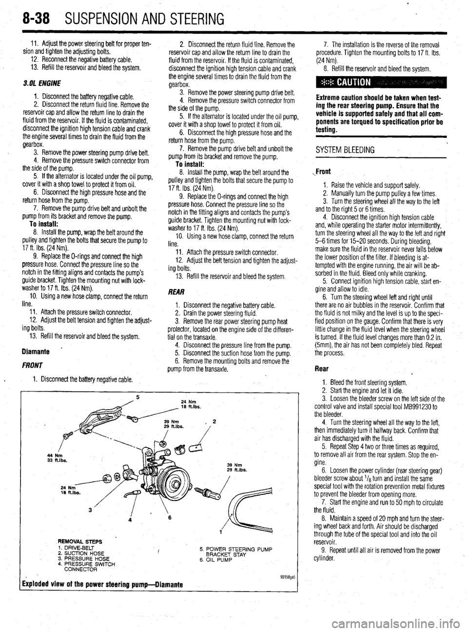
REMOVAL STEPS
5. POWER STEERING PUMP
BRACKET STAY
6. OIL PUMP 1. DRIVE-BELT
2. SUCTION HOSE I ’ 3. PRESSURE HOSE
4. PRESSURE SWITCH
CONNECTOR
Exploded view of the power steering pump-Diamante
. 93158ga5
7. The installation is the reverse of the removal
procedure. Tighten the mounting bolts to 17 ft. Ibs.
(24 Nm).
8. Refill the reservoir and bleed the system.
Extreme caution should be taken when test-
ing the rear steering pump. Ensure that the
vehicle is supported safely and that all com-
ponents are torqued to specification prior be
testing.
. SYSTEM BLEEDING
,Front
1. Raise the vehicle and support safely.
2. Manually turn the pump pulley a few times.
3. Turn the steering wheel all the way to the left
and to the right 5 or 6 times.
4. Disconnect the ignition high tension cable
and, while operating the starter motor intermittently,
turn the steering wheel all the way to the letI and right
5-6 times for 15-20 seconds. During bleeding,
make sure the fluid in the reservoir never falls below
the lower position of the filter. If bleeding is at-
tempted with the engine running, the air will be ab-
sorbed in the fluid. Bleed only while cranking.
5. Connect ignition high tension cable, start en-
gine and allow to idle.
6. Turn the steering wheel left and right until
there are no air bubbles in the reservoir. Confirm that
the fluid is not milky and the level is up to the speci-
fied position on the gauge. Confirm that there is very
little change in the fluid level when the steering wheel
is turned. If the fluid level changes more than 0.2 in.
(5mm), the air has not been completely bled. Repeat
the process.
Rear
.
1. Bleed the front steering system.
2. Start the engine and let it idle.
3. Loosen the bleeder screw on the left side of the
control valve and install special tool MB991230 to
the bleeder.
4. Turn the steering wheel all the way to the left,
then immediately turn it halfway back. Confirm that
air has discharged with the fluid.
5. Repeat Step 4 two or three times as required,
to remove all air from the rear system. Stop the en-
gine.
6. Loosen the power cylinder (rear steering gear)
bleeder screw about I/* turn and install the same
special tool with the rotation prevention metal fixtures
to prevent the bleeder from opening more.
7. Start the engine and run to 50 mph to circulate
the fluid.
8. Maintain a speed of 20 mph and turn the steer-
ing wheel back and forth. Air should be discharged ,
through the tube of the special tool and into the oil
reservoir.
9. Repeat until all air is removed from the power
cylinder.
Page 341 of 408
BRAKES 9-5
Inspect brake pedal free-play
firm that the amount of movement before resistance
is felt is within 0.1-0.3 in. (3-8mm).
3. If the free-play is less than desired, confirm
that the brake light switch is in proper adjustment.
4. If there is excessive free-play, look for wear or
play in the clevis pin and brake pedal arm. Replace
worn parts as required and recheck brake pedal free-
Play*
REMOVAL &INSTALLATION '
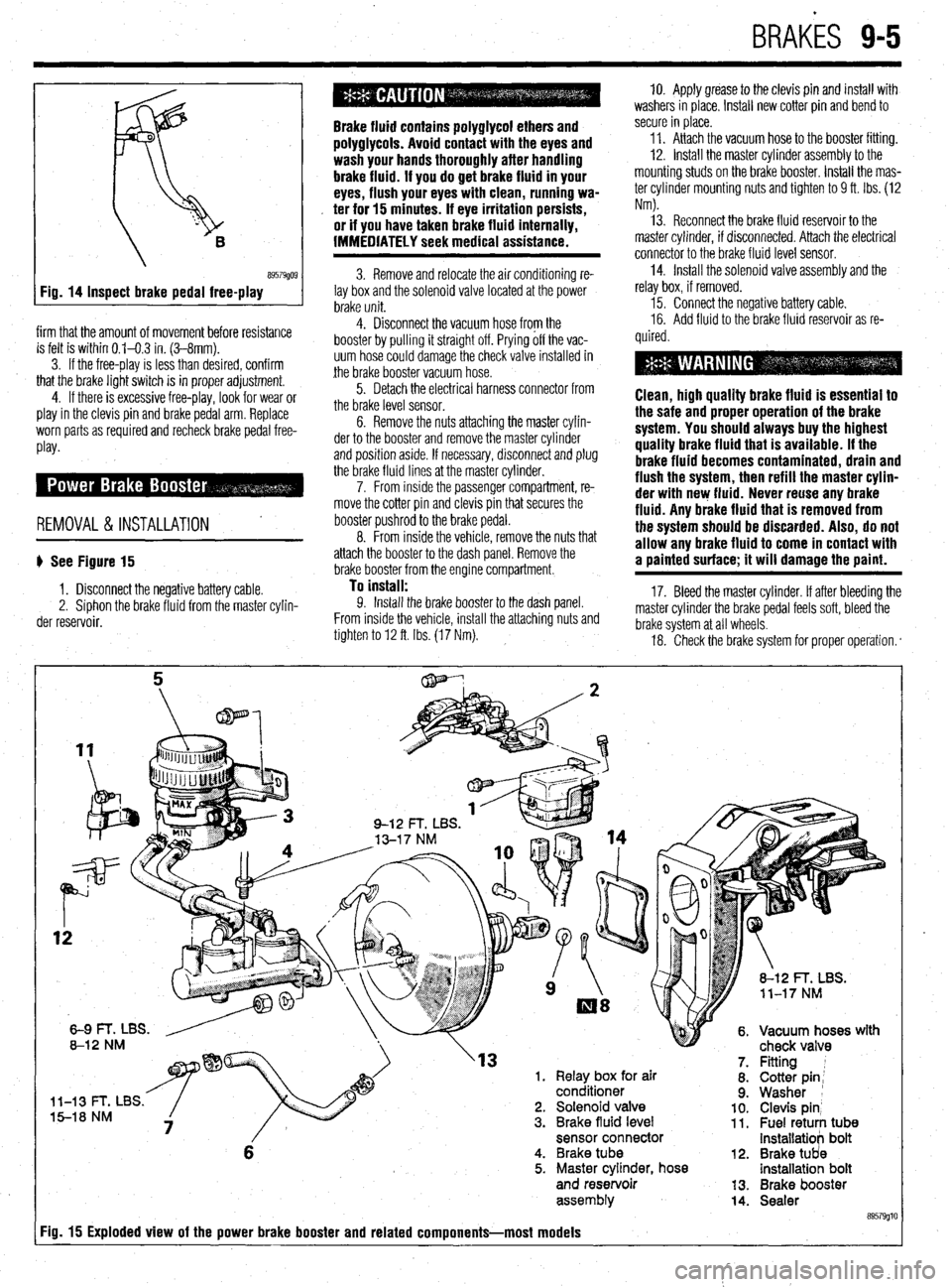
b See Figure 15
1. Disconnect the negative battery cable.
2. Siphon the brake fluid from the master cylin-
der reservoir.
Brake fluid contains polyglycol ethers and
polyglycols. Avoid contact with the eyes and
wash your hands thoroughly after handling
brake fluid. If you do get brake fluid in your
eyes, flush your eyes with clean, running wa-
. ter for 15 minutes. If eye irritation persists,
or if you have taken brake fluid internally,
IMMEDIATELY seek medical assistance.
3. Remove and relocate the air conditioning re-
lay box and the solenoid valve located at the power
brake unit.
4. Disconnect the vacuum hose from the
booster by pulling it straight off. Prying off the vac-
uum hose could damage the check valve installed in
the brake booster vacuum hose.
5. Detach the electrical harness connector from
the brake level sensor.
6. Remove the nuts attaching the master cylin-
der to the booster and remove the master cylinder
and position aside. If necessary, disconnect and plug
the brake fluid lines at the master cylinder.
7. From inside the passenger compartment, re-
move the cotter pin and clevis pin that secures the
booster pushrod to the brake pedal.
8. From inside the vehicle, remove the nuts that
attach the booster to the dash panel. Remove the
brake booster from the engine compartment.
To install: 9. Install the brake booster to the dash panel.
From inside the vehicle, install the attaching nuts and
tighten to 12 ft. Ibs. (17 Nm). 10. Apply grease to the clevis pin and install with
washers in place. Install new cotter pin and bend to
secure in place.
11. Attach the vacuum hose to the booster fitting.
12. Install the master cylinder assembly to the
mounting studs on the brake booster. Install the mas-
ter cylinder mounting nuts and tighten to 9 ft. Ibs. (12
Nm).
13. Reconnect the brake fluid reservoir to the
master cylinder, if disconnected. Attach the electrical
connector to the brake fluid level sensor.
14. Install the solenoid valve assembly and the
relay box, if removed.
15. Connect the negative battery cable.
16. Add fluid to the brake fluid reservoir as re-
quired.
Clean, high quality brake fluid is essentlal to
the safe and proper operation of the brake
system. You should always buy the highest
quality brake fluid that is available. If the
brake fluid becomes contaminated, drain and
flush the system, then refill the master cylin-
der with new fluid. Never reuse any brake
fluid. Any brake fluid that is removed from
the system should be discarded. Also, do not
allow any brake fluid to come in contact with
a painted surface; it will damage the paint.
17. Bleed the master cylinder. If after bleeding the
master cylinder the brake pedal feels soft, bleed the
brake system at all wheels.
18. Check the brake system for proper operation. *
rn( mr
'13 1. Relay box for air
conditioner
l-13 t- I, Ltx5. 5-18 NM 2. Solenoid valve
3. Brake fluid level
sensor connector
6 4. Brake tube
5. Master cylinder, hose
and reservoir
assem biy
Fig. 15 Exploded view of the power brake booster and related components-most models
12.
13.
14. Fitting 1
Cotter pin;
Washer 1
Clevis pin’ Fuel retuti tub8 installatiob bolt
Brake tUd8 installatioh bolt
Brake booster
Sealer
89579glt
Page 343 of 408
BRAKES 9-7
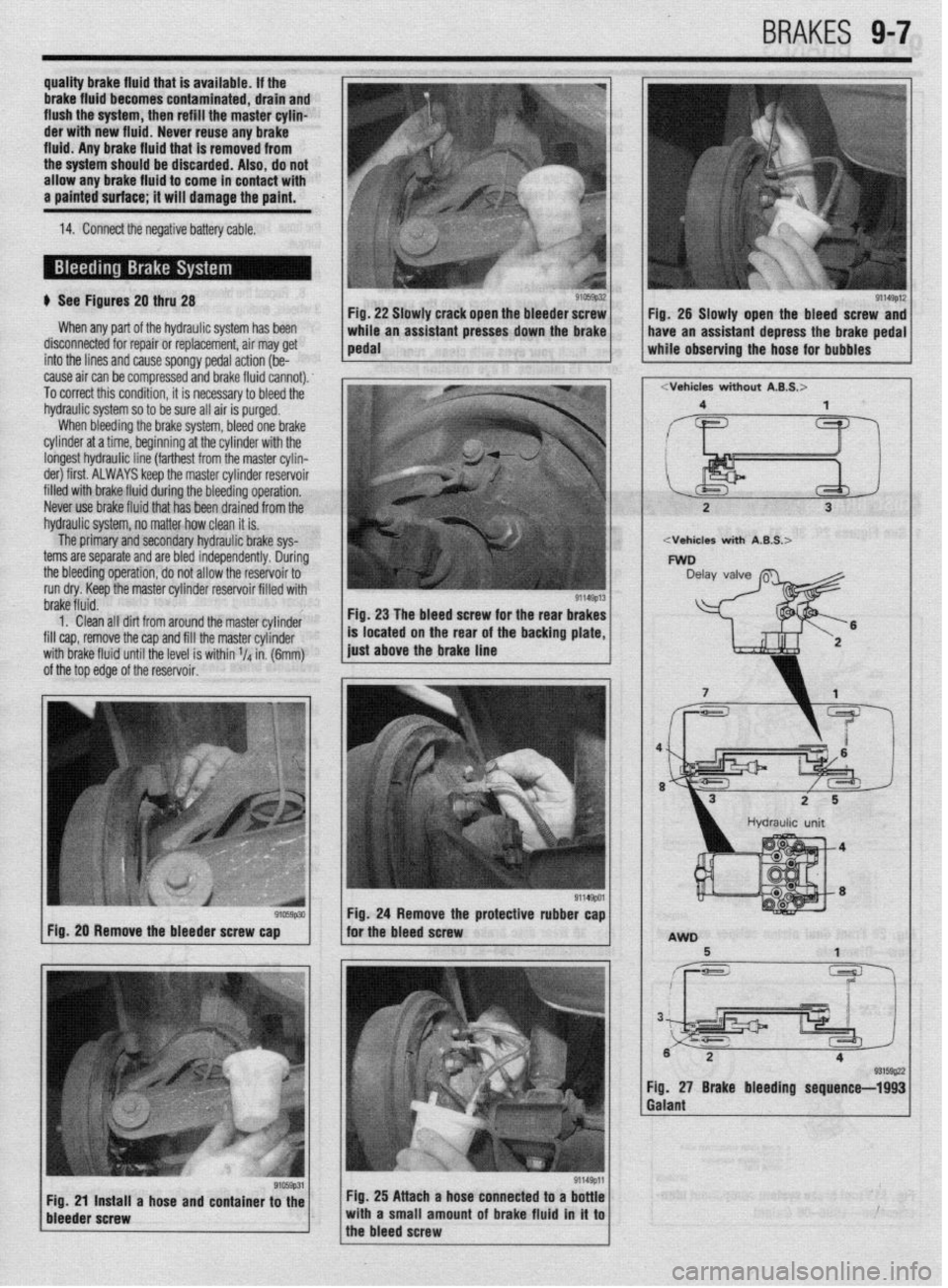
b See Figures 20 thru 28
When any part of the hydraulic system has been
disconnected for repair or replacement, air may get
into the lines and cause spongy pedal action (be-
cause air can be compressed and brake fluid cannot).
To correct this condition, it is necessary to bleed the
hydraulic system so to be sure all air is purged.
When bleeding the brake system, bleed one brake
cylinder at a time, beginning at the cylinder with the
longest hydraulic line (farthest from the master cylin-
der) first. ALWAYS keep the master cylinder reservoir
filled with brake fluid during the bleeding operation,
Never use brake fluid that has been drained from the
hydraulic system, no matter how clean it is.
The primary and secondary hydraulic brake sys-
terns are separate and are bled independently. During
the bleeding operation, do not allow the reservoir to
run dry. Keep the master cylinder reservoir filled with Fig. 22 Slawly crack open the bleeder screw
brake fluid.
1. Clean all dirt from around the master cylinder
fill cap, remove the cap and fill the master cylinder
with brake fluid until the level is within V4 in. (6mm)
of the top edge of the reservoir. Fig, 23 The bleed screw for the rear brakes
91059p30 Fig. 20 Remove the bleeder screw cap Fig. 28 Slowly open the bleed screw and
Fig, 27 Brake bleeding sequence-1993
Galant
Fig. 25 Attach a hose connected to a bottle
with a small amount of brake fluid in it to
the bleed screw
Page 344 of 408
9-8 BRAKES
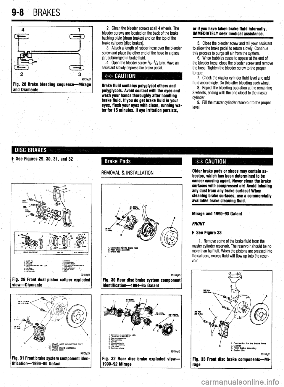
2
3 93159g27 Fig. 28 Brake bleeding sequence-Mirage
and Diamante
1
2, Clean the bleeder screws at all 4 wheels. The
bleeder screws are located on the back of the brake
backing plate (drum brakes) and on the top of the
brake calipers (disc
brakes). 3. Attach a length of rubber hose over the bleeder
screw and place the other end of the hose in a glass
jar, submerged in brake fluid.
4. Open the bleeder screw l/r3/4 turn. Have an
assistant slowly depress the brake pedal.
Brake fluid contains polyglycol ethers and
poiygiycois. Avoid contact with the eyes and
wash your hands thoroughly after handling
brake fluid. if you do get brake fluid in your
eyes, flush your eyes with clean, running wa-
ter for 15 minutes. if eye irritation persists, or if you have taken brake fluid internally,
IMMEDIATELY seek medical assistance.
5. Close the bleeder screw and tell your assistant
to allow the brake pedal to return slowly. Continue
this process to purge all air from the system.
6. When bubbles cease to appear at the end of
the bleeder hose, close the bleeder screw and remove
the hose. Tighten the bleeder screw to the proper
torque:
7. Check the master cylinder fluid level and add
fluid accordingly. Do this after bleeding each wheel,
8. Repeat the bleeding operation at the remaining
3 wheels, ending with the one closet to the master
cylinder.
9. Fill the master cylinder reservoir to the proper
level.
# See Figures 29, 30, 31, and 32
REMOVAL &INSTALLATION
.
I. C”lDE PIN 8 mm
2 LdcK Pm 9 PlSToN SEAL
3 WSHINO 10 WPER BODY
4 CALIPER 9lJPwRT ,pM. cue
sH’YlcYaT , 11 PmE~~yvEm INLKATclR
: EiT Rim 12 PAD As&&w
7 PWON mm ;: w&E” SHlM ,
93159g28 Fig. 29 Front dual piston caliper exploded
view-Diamante ‘a
L
1. BRAKE HOSE CONNECTOR BOLT
2. GASKET
’ 3. FRONT BRAKE ASSEMBLY
4. BRAKE DISC
93159g; Fig. 31 Front brake system component iden
tification-1996-00 Gaiant !9
I- 93159g23
Fig. 30 Rear disc brake system component
identification-1994-95 Galant
3 Rear brake ar?.embiy
4 Rear Drake dnc
5 Hubcap
6 Wheel baanng tit
7 Flew hub assemblv
8 chlstshteki
9 DISC brake adapter
93159glC
Fig. 32 Rear disc brake exploded view-
1996-92 Mirage Older brake pads or shoes may contain as-
bestos, which has been determined to be
cancer causing agent. Never clean the brake
surfaces with compressed air! Avoid inhaling
any dust from any brake surface! When
cieanlng brake surfaces, use a commercially
available brake cleaning fluid.
Mirage and 1990-93 Gaiant *
FRONT
@ See Figure 33
1. Remove some of the brake fluid from the
master cylinder reservoir. The reservoir should be no
more than half full. When the pistons are pressed into
the calipers, excess fluid will flow up into the reser-
voir.
I
1. Cons for the brake hose
3 2. Gasket
3. Front brake assembly
4. Brake disc
93159911
Fig. 33 Front disc brake components-Mi-
rage
Page 347 of 408
BRAK& 9-11
1, Disconnect the battery negative cable.
2. Raise the vehicle and support safely.
3. Remove the appropriate tire and wheel as-
---L,:--
SeIIIUIIM. 4. Loosen the parking brake cable adjustment
from inside the vehicle.
B957wJ FIQ. 48 Inspect front disc pad thickness Brake pads an
which has bee
causing agent
faces with con
any dust fmm
brakes, use cf Id shoes contaln
asbestos, !n determined to be a cancer
. Never clean the brake SUP
npressed air! Avoid inhaling
brake surfaces! When cleaning
lmmercially available brake
c
cleaning fluid 5. Remove the retaining clips, and disconnect
the parking brake cable from the rear brake caliper
assembly.
rflo not let ali into the master cylinder by
allowing the reservoir to empty or complete
system bleeding will be required.
6. On FWD models, to disconnect the brake
nose rrom me canoer. remove me
oamo
DOII nom me
through caliper body check port
Mirage and 199Q-93 Galant brake caliper. ’
7. On AWD models, hold the nut on the brake
hose side and loosen the flared brake line nut. With
the hose disconnected at the line, remove the brake
hose from the caliper.
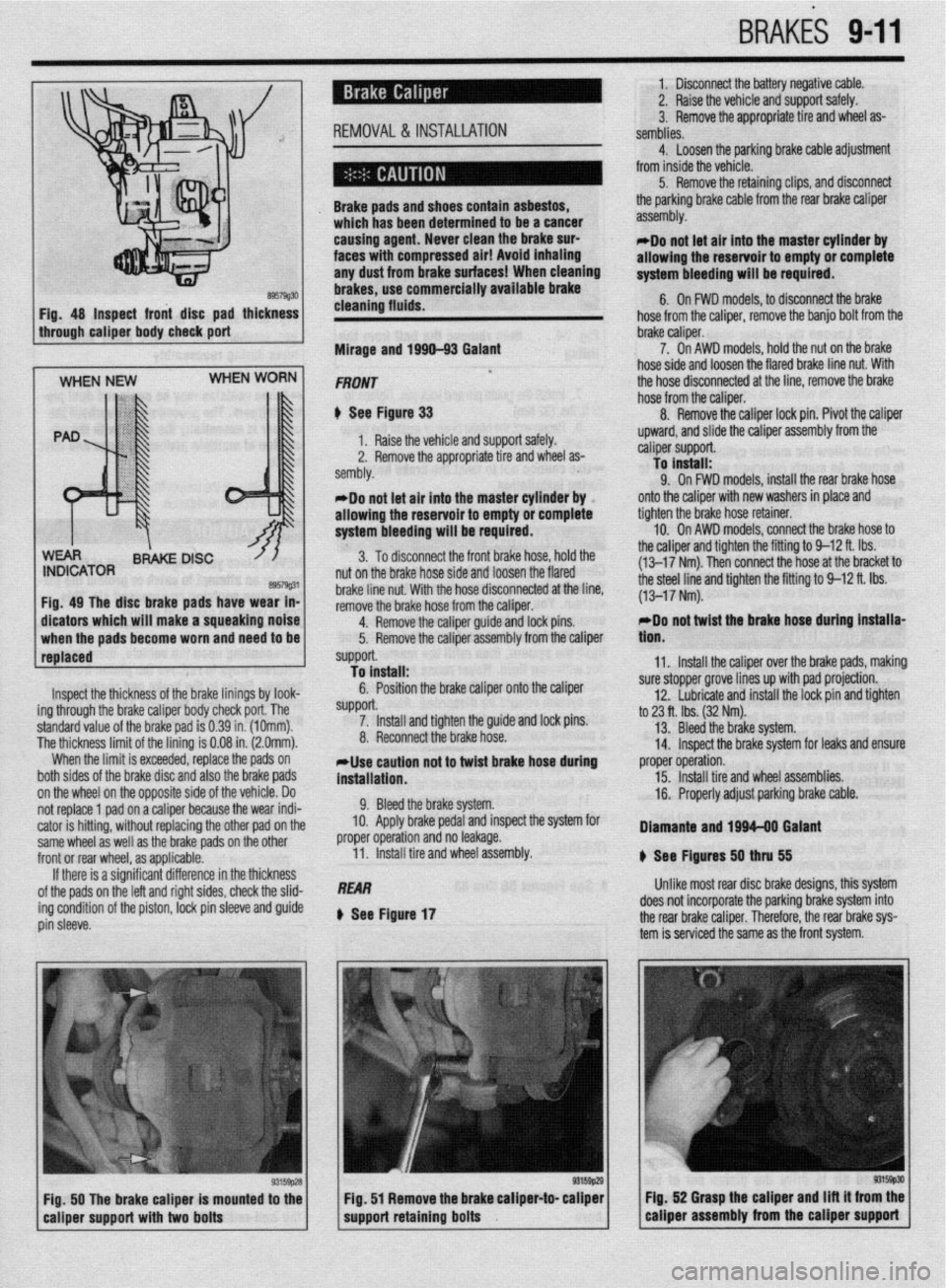
8. Remove the caliper lock pin. Pivot the caliper
Inspect the thickness of the brake linings by look-
ing through the brake caliper body check port. The
standard value of the brake pad is 0.39 in. (1Omm).
The thickness limit of the lining is 0.08 in. (2.0mm).
When the limit is exceeded, replace the pads on
both sides of the brake disc and also the brake pads
on the wheel on the opposite side of the vehicle. Do
not replace 1 pad on a caliper because the wear indi-
cator is hitting, without replacing the other pad on the
same wheel as well as the brake pads on the other
front or rear wheel, as applicable.
If there is a significant difference in the thickness
of the pads on the left and right sides, check the slid-
ing condition of the piston,
IDCk pin sleeve and guide
pin sleeve. *Do not let air into the master cylinder by
allowing the reservoir to empty or complete
system bleeding will be required.
3. To disconnect the front brake hose, hold the
nut on the brake hose side and loosen the flared
brake line nut. With the hose disconnected at the line,
remove the brake hose from the caliper.
4.
RfXIIDVe the caliper guide and lock pins.
5. Remove the caliper assembly from the caliper
support.
To install:
6. Position the brake caliper onto the caliper
SUppOrt. 7. Install and tighten the guide and lock pins.
8. Reconnect the brake hose.
*Use caution not to twist brake hose during
installation.
9. Bleed the brake system.
10. Apply brake pedal and inspect the system for
proper operation and no leakage.
11. Install tire and wheel assembly.
REAR
Q See Figure 17 upward, and slide the caliper assembly from the
caliper support.
To install:
9. On FWD models, install the rear brake hose
onto the caliper with new washers in place and
tighten the brake hose retainer.
10. On AWD models, connect the brake hose to
the caliper and tighten the fitting to 9-12 ft. Ibs.
(13-17 Nm). Then connect the hose at the bracket to
the steel line and tighten the fitting to 9-12 ft. Ibs.
(13-17 Nm).
rDo not twist the brake hose during installa-
tlon.
11. Install the caliper over the brake pads, making
sure stopper grove lines up with pad projection.
12. Lubricate and install the lock pin and tighten
to 23 ft. tbs. (32 Nm).
13. Bleed the brake system.
14. Inspect the brake system for leaks and ensure
proper operation.
15. Install tire and wheel assemblies.
16. Properly adjust parking brake cable.
Diamante and 1994-08 Galant
8 See Ffgures 50
thN 55
Unlike most rear disc brake designs, this system
does not incorporate the parking brake system into
the rear brake caliper. Therefore, the rear brake sys-
tem is serviced the same as the front system.
FiQ. 50 The brake caliper is mounted to the Fig. 52 Grasp the caliper and Ilft it from the
eaiiper support with two bolts support retaining bolts caliper assembly from the caliper support
Page 348 of 408
l
942 BRAKES
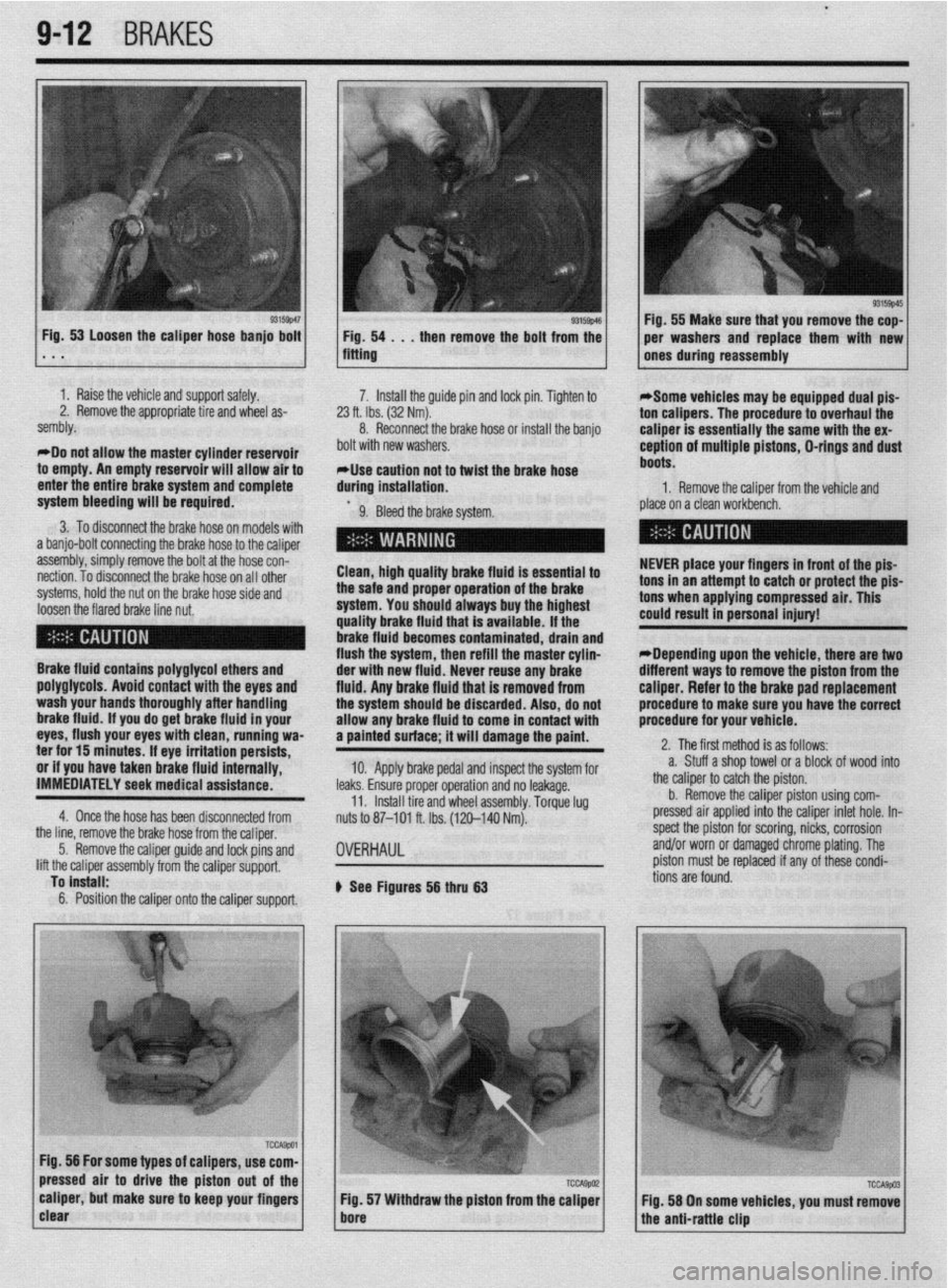
I 93155~46 Fig, 53 Loosen the caliper hose banjo bolt
1 Fig. 54 . . , then remove the bolt from the . * . fitting
1 I Raise the vehicle and support safely.
2. Remove the appropriate tire and wheel as-
sembly.
*Do not allow the master cylinder reservoir
to empty. An empty reservoir will allow air to
enter the entire brake system and complete 7. Install the guide pin and lock pin. Tighten to
23 ft. Ibs. (32 Nm).
8. Reconnect the brake hose of install the banjo
bolt with new washers.
*Use caution not to twist the brake hose
during installation.
system bleeding will be required.
9. Bleed the brake system.
3. To disconnect the brake hose on models with
a banjo-bolt connecting the brake hose to the caliper
assembly, simply remove the bolt at the hose con-
nection. To disconnect the brake hose on all other
systems, hold the nut on the brake hose side and
loosen the flared brake line nut. Clean, high quality brake fluid is essential to
the safe and proper operation of the brake
system. You should always buy the highest
quality brake fluid that is available. If the
brake fluid becomes contaminated, drain and
flush the system, then refill the master cylin-
Brake fluid contains polyglycol ethers and
poly~lycols. Avoid contact with the eves and
wash your hands thoroughly after handling
brake fluid. if you do get brake fluid In your
eyes, flush your eyes with clean, running wa-
ter for 15 minutes. If eye irritation persists,
or if you have taken brake fluid internally,
IMMEDIATELY seek medical assistance.
4. Once the hose has been disconnected from der with new fluid. Never reuse any brake
fluid. Anv brake fluid that is removed from
the systum should be discarded. Also, do not
allow any brake fluid to come in contact with
a painted surface; it will damage the paint.
10. Apply brake pedal and inspect the system for
leaks. Ensure proper operation and no leakage.
11. Install tire and wheel assembly. Torque lug
nuts to 87-101 ft. Ibs. (120-140 Nm).
the line, remove the brake hose from the caliper,
5. Remove the caliper guide and lock pins and
lift the caliper assembly from the caliper support,
To install:
6. Position the caliper onto the caliper support.
OVERHAUL
b See Figures 56 thru 63 1 Fig. 55 Make sure that you remove the cop-
per washers and replace them with new
ones during reassembly
*Some vehicles may be equipped dual pis-
ton calipers. The procedure to overhaul the
caliper is essentially the same with the ex-
ception of multiple pistons, D-rings and dust
boots.
1. Remove the caliper from the vehicle and
place on a clean workbench.
NEVER place your fingers in front of the pis-
tons in an attempt to catch or protect the pis-
tons when applying compressed air. This
could result in personal injury!
*Depending upon the vehicle, there are two
different ways to remove the piston from the
caliper. Refer to the brake pad replacement
procedure to make sure you have the correct
procedure for your vehicle.
2. The first method is as follows:
a. Stuff a shop towel or a block of wood into
the caliper to catch the piston.
b. Remove the caliper piston using com-
pressed air applied into the caliper inlet hole. In-
spect the piston for scoring, nicks, corrosion
and/or worn or damaged chrome plating. The
piston must be replaced if any of these condi-
tions are found.
Page 355 of 408
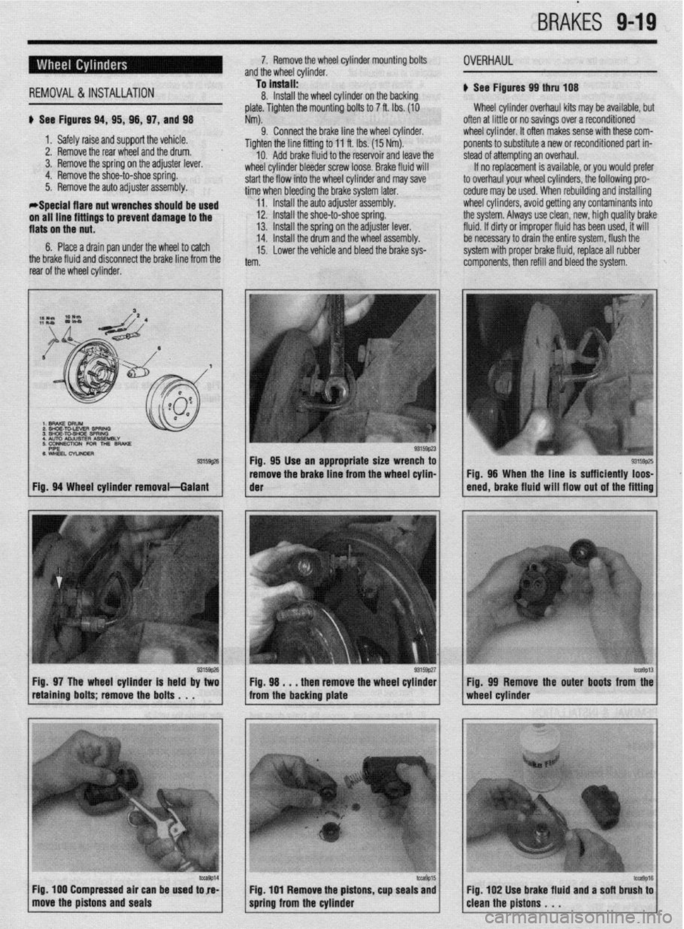
BRAtiES 9-19
*Soecial flare nut wrenches shauld
REMOVAL&INSTALLATION
be used u See Figures 94, 95, 98, 97, and 98
1. Safely raise and support the vehicle.
2. Remove the rear wheel and the drum.
3. Remove the spring on the adjuster lever,
4. Remove the shoe-to-shoe spring.
5. Remove the auto adjuster assembly. 7. Remove the wheel cylinder mounting bolts
and the wheel cylinder.
To install:
11. Install the auto adjusterassembly. 8. Install the wheel cylinder on the backing
plate. Tighten the mounting bolts to 7 ft. Ibs. (10
Nm).
9. Connect the brake line the wheel cylinder.
Tighten the line fitting to 11 ft. Ibs. (15 Nm).
10. Add brake fluid to the reservoir and leave the
wheel cylinder bleeder screw loose. Brake fluid will
start the flow into the wheel cylinder and may save
time when bleeding the brake system later.
OVERHAUL
u See Figures 99 thru lD8
Wheel cylinder overhaul kits may be available, but
often at little or no savings over a reconditioned
wheel cvlinder. It often makes sense with these com-
ponents to substitute a new or reconditioned part in-
stead of attempting an overhaul.
If no replacement is available, or you would prefer
to overhaul your wheel cylinders, the following pro-
cedure may be used. When rebuilding and installing
wheel cylinders, avoid getting any contaminants into
the system. Always use clean, new, high quality brake
fluid. If dirty or improper fluid has been used, it will
be necessary to drain the entire system, flush the
system with proper brake fluid, replace all rubber
components, then refill and bleed the system.
Fig. 97 The wheel cylinder is held by two Fig. 98 . . . then remove the wheel cylinder
retaining bolts; remove the bolts . . . from the backing plate
/ move the pistons and seals ‘Tr 1 Fig 100 Compressed air can be used tore- Fig. 99 Remove the outer boots from the
/cleanthepistons. ‘. ‘*I6 Fig 102 Use brake fluid and a sofl brush to
Page 393 of 408
TROUBLESHOOTlNGll-11
b. Driveshaft misaligned. Check for collapsed or damaged engine and transmission
mounts, and replace as necessary.
c. Driveshaft bent or out of balance. Replace damaged components and reinstall.
d. Driveshaft out of balance. Remove the driveshaft and have it balanced by a competent
professional, or replace the driveshaft assembly.
NOTE: Most driveshafts are linked together by universal joints; however,
some manufacturers use Constant Velocity (CV) joints or rubber flex cou-
plers.
All Wheel and Four Wheel Drive Vehicles
1. Front or rear wheel makes a clicking noise
a. Check for debris such as a pebble, nail or glass in the tire or tire tread. Carefully re-
move the debris. Small rocks and pebbles rarely cause a puncture; however, a sharp
object should be removed carefully at a facility capable of performing tire repairs.
b. Check for a loose, damaged or worn Constant Velocity (CV) joint and replace if defec-
tive.
2. Front or rear wheel vibrates wlth Increased speed
a. Check for a bent rim and replace, if damaged.
b. Check the tires for balance or internal damage and replace if defective.
c. Check for a loose, worn or damaged wheel bearing and replace if defective.
d. Check for a loose, damaged or worn Constant Velocity (CV) joint and replace if defec-
tive.
Front Wheel Drive Vehicles
3. Front wheel makes a c&kin@ noise
a. Check for debris such as a pebble, nail or glass in the tire or tire tread. Carefully re-
move the debris. Small rocks and pebbles rarely cause a puncture; however, a sharp
object should be removed carefully at a facility capable of performing tire repairs.
b. Check for a loose, damaged or worn Constant Velocity (CV) joint and replace if defec-
tive. 4. Rear wheel makes a clicking noise
a. Check for debris such as a pebble, nail or glass in the tire or tire tread. Carefully re-
move the debris. Small rocks and pebbles rarely cause a puncture; however, a sharp
object should be removed carefully at a facility capable of performing tire repairs.
Rear Wheel Drive Vehicles
5. Front or rear wheel makes a clicking noise
a. Check for debris such as a pebble, nail or glass in the tire or tire tread. Carefully re-
move the debris. Small rocks and pebbles rarely cause a puncture; however, a sharp
object should be removed carefully at a facility capable of performing tire repairs.
6. Rear wheel shudders or vibrates
a. Check for a bent rear wheel or axle assembly and replace defective components.
b. Check for a loose, damaged or worn rear wheel bearing and replace as necessary.
1. Burning odor from center of vehicle when accelerating
a. Check for a seizing brake hydraulic component such as a brake caliper. Check the
caliper piston for surface damage such as rust, and measure for out-of-round wear
and caliper-to-piston clearance. For additional information on brake related odors, re-
fer to section 3-A, condition number 9.
b. On vehicles with a manual transmission, check for a slipping clutch. For possible
causes and additional information, refer to section Z-C, condition number 1.
c. On vehicles with an automatic transmission, check the fluid level and condition, Top
off or change the fluid and filter using the recommended replacement parts, lubricant
type and amount. If the odor persists, transmission removal and disassembly will be
necessary.
2. Engine accelerates, but vehicle does not gain speed
a. On vehicles with a manual transmission, check for a slipping or damaged clutch. For
possible causes and additional information refer to section Z-C, condition number 1.
b. On vehicles with an automatic transmission, check the fluid level and condition. Top
off or change the fluid and filter using the recommended replacement parts, lubricant
type and amount. If the slipping continues, transmission removal and disassembly will
be necessary.
1. Brake pedal pulsates or shimmies when pressed
a. Check wheel lug nut torque and tighten evenly to specification.
b. Check the brake rotor for trueness and thickness variations. Replace the rotor if it is
too thin, warped, or if the thickness varies beyond specification. Some rotors can be
machined: consult the manufacturer’s specifications and recommendations before us-
ing a machined brake rotor.
c. Check the brake caliper or caliper bracket mounting bolt torque and inspect for loose-
ness. Torque the mounting bolts and inspect for wear or any looseness, including
worn mounting brackets, bushings and sliding pins.
d. Check the wheel bearing for looseness. If the bearing is loose, adjust if possible, oth-
erwise replace the bearing.
2. Brakes make a squealing noise
a. Check the brake rotor for the presence of a ridge on the outer edge; if present, remove
the ridge or replace the brake rotor and brake pads.
b. Check for debris in the brake lining material, clean and reinstall.
c. Check the brake linings for wear and replace the brake linings if wear is approaching
the lining wear limit.
d. Check the brake linings for glazing. Inspect the brake drum or rotor surface and re-
place, along with the brake linings, if the surface is not smooth or even.
e. Check the brake pad or shoe mounting areas for a lack of lubricant or the presence of
surface rust. Clean and lubricate with a recommended high temperature brake grease.
3. Brakes make a flrindinfl noise
a. Check the brake linings and brake surface areas for severe wear or damage. Replace
worn or damaged parts.
b. Check for a seized or partially seized brake causing premature or uneven brake wear,
excessive heat and brake rotor or drum damage. Replace defective parts and inspect
the wheel bearing condition, which could have been damaged due to excessive heat.
4. Vehicle pulls to one side during braking
a. Check for air in the brake hydraulic system. Inspect the brake hydraulic seals, fluid
lines and related components for fluid leaks. Remove the air from the brake system by bleeding the brakes. Be sure to use fresh brake fluid that meets the manufacturers rec-
ommended standards.
b. Check for an internally restricted flexible brake hydraulic hose. Replace the hose and
flush the brake system.
c. Check for a seizing brake hydraulic component such as a brake caliper. Check the
caliper piston for surface damage such as rust, and measure for out-of-round wear
and caliper-to-piston clearance. Overhaul or replace failed parts and flush the brake
system.
d. Check the vehicle’s alignment and inspect for suspension wear. Replace worn bush-
ings, ball joints and set alignment to the manufacturers specifications.
e. If the brake system uses drum brakes front or rear, check the brake adjustment. Inspect
for seized adjusters and clean or replace, then properly adjust.
5. Brake pedal feels spongy or has excessive travel
a. Check the brake fluid level and condition. If the fluid is contaminated or has not been
flushed every two years, clean the master cylinder reservoir, and bleed and flush the
brakes using fresh brake fluid that meets the manufacturers recommended standards.
b. Check for a weak or damaged flexible brake hydraulic hose. Replace the hose and
flush the brake system.
c. If the brake system uses drum brakes front or rear, check the brake adjustment. Inspect
for seized adjusters and clean or replace, then properly adjust.
6. Brake pedal feel is firm, but brakes lack sufficient stopping power or
fade
a. Check the operation of the brake booster and brake booster check valve: Replace worn
or failed parts.
b. Check brake linings and brake surface areas for glazing and replace worn or damaged
parts.
c. Check for seized hydraulic parts and linkages, and clean or replace as needed.
7. Vehicle has excessive front end dive or locks rear brakes too easily
a. Check for worn, failed or seized brake proportioning valve and replace the valve.
b. Check for a seized, disconnected or missing spring or linkage for the brake propor-
tioning valve. Replace missing parts or repair as necessary.