timing belt MITSUBISHI DIAMANTE 1900 Repair Manual
[x] Cancel search | Manufacturer: MITSUBISHI, Model Year: 1900, Model line: DIAMANTE, Model: MITSUBISHI DIAMANTE 1900Pages: 408, PDF Size: 71.03 MB
Page 1 of 408
HOW TO USE THIS BOOK 1-2
WHERE TOBEGIN l-2
AVOIDINGTROUBLE 1-2
MAINTENANCEORREPAIR? 1-2
AVOIDINGTHEMOSTCOMMONMISTAKES l-2
TOOLS AND EQUIPMENT 1-2
SPECIALTOOLS l-4
YOUR VEHICLE SAFELY 1-4
DON'TS l-6
FASTENERS, MEASUREMENTS AND
CONVERSIONS l-6
BOLTS,NUTSANDOTHERTHREADED
RETAINERS 1-6
TORQUE l-7
TORQUEWRENCHES l-7
TORQUEANGLEMETERS 1-9
STANDARDANDMETRIC MEASUREMENTS l-9
SERIAL NUMBER IDENTIFICATION l-10
VEHICLE IDENTIFICATION NUMBER l-10
ENGINE IDENTIFICATION NUMBER I-10
TRANSAXLEIDENTIFICATION I-10
DRlVEAXLE(AWDGALANTONLY) l-10
TRANSFERCASE(AWDGALANTONLY) l-10
ROUTINE MAINTENANCE AND TUNE-UP l-14
AIRCLEANER(ELEMENT) 1-14
REMOVAL&INSTALLATION 1-14
FUELFILTER 1-15
REMOVAL &INSTALLATION l-15
PCVVALVE l-15
REMOVAL&INSTALLATION l-15
EVAPORATIVECANISTER l-16
SERVICING 1-16
BATTERY 1-16
PRECAUTIONS I-16
GENERALMAINTENANCE 1-16
BEL BATTERYFLUID 1-16
CABLES I-17
CHARGING I-18
REPLACEMENT 1-18
TS 1-18
INSPECTiON l-18
ADJUSTMENT 1-18
REMOVAL&INSTALLATION 1-18
TIMINGBELTS l-20
INSPECTION l-20
HOSES I-20
INSPECTION l-20
REMOVAL&INSTALLATION
CV-BOOTS 1-21
INSPECTION l-21
SPARKPLUGS l-22
SPARKPLUGHEATRANGE
REMOVAL&INSTALLATION
INSPECTION &GAPPING 1.
SPARKPLUG WIRES 1-24
TESTING 1-24
REMOVAL&INSTALLATION
DISTRIBUTORCAPANDROTOR
REMOVAL&INSTALLATION
INSPECTION 1-25
IGNITIONTIMING 1-25
. GENERALINFORAMTION l-
lNSPECTlON&ADJUSTMENl
VALVE LASH l-27
ADJUSTMENT l-27
IDLESPEED 1-28 1-21
l-22
l-22
-23
1-24
l-25
l-25
.25
1-26
AIR CONDITIONING SYSTEM 1-28
SYSTEMSERVlCEiiREPAlR l-28
PREVENTIVEMAINTENANCE 1-28
SYSTEM INSPECTION l-29
WINDSHIELD WIPERS l-29
ELEMENT(REFILL)CARE&
REPLACEMENT l-29
TIRESANDWHEELS l-30
TIRE ROTATION I-30
TIRE DESIGN 1-31
TIRESTORAGE l-31
INFLATION &INSPECTION l-31
CARE OFSPECIALWHEELS l-32 OPERATION INFOREIGNCOUNTRIES l-33
ENGINE l-33
OILLEVELCHECK 1-33
OIL& FILTER CHANGE l-34
MANUALTRANSAXLE l-35
FLUIDRECOMMENDATIONS l-35
LEVELCHECK l-35
DRAIN&REFILL l-36
AUTOMATICTRANSAXLE l-36
FLUIDRECOMMENDATIONS l-36
LEVELCHECK 1-36
DRAIN&REFILL l-36
PAN & FILTERSERVICE 1-36
TRANSFERCASE(AWDGAlANT ONLY) l-38
FLUIDRECOMMENDATIONS l-38
LEVELCHECK l-38
DRAIN&REFILL l-38
REARDRlVEAXLE(AWDGALANTONLY) l-38
FLUIDRECOMMENDATIONS l-38
LEVELCHECK l-38
DRAIN&REFILL l-38
COOLINGSYSTEM l-39
FLUIDRECOMMENDATIONS l-39
iM-41
FLUIDS AND LUBRICANTS 1-33
FLUID DISPOSAL 1-33
FlJELANDENGlNEOILRECOMMENDATlONS
ENGINE OIL l-33
FUEL l-33
Page 19 of 408
.
l-20 GENERALINFORMATIONAND MAINTENANCE
INSPECTION
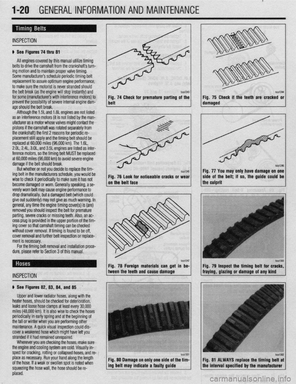
# See Figures 74 thru 81
All engines covered by this manual utilize timing
belts to drive the camshaft from the crankshafts turn-
ing motion and to maintain proper valve timing.
Some manufacturers schedule periodic timing belt
replacement to assure optimum engine performance,
to make sure the motorist is never stranded should
the belt break (as the engine will stop instantly) and
for some (manufacturers with interference motors) to
prevent the possibility of severe internal engine dam-
age
St10Ula the Delt break. Although the 1.5L and 1.8L engines are not listed
as an interference motors (it is not listed by the man-
ufacturer as a motor whose valves might contact the
pistons if the camshaft was rotated separately from
the crankshaft) the first 2 reasons for periodic re-
placement still apply and the timing belt should be
replaced at 60,000 miles (96,000 km). The 1.6L,
2.01,2.4L, 3.OL, and 35L engines are listed as inter-
ference motors, so the timing belt MUST be replaced
at 60,000 miles (96,000 km) to avoid severe engine
damage if the belt should break.
But whether or not you decide to replace the tim-
ing belt in the manufacturers schedule, you would be
wise to check it periodically to make sure it has not
become damaged or worn. Generally speaking, a se-
verelv worn belt mav cause enaine oerformance to
drop~dramatically, but a damaged belt (which could
give out suddenly) may not give as much warning. In
general, any time the engine timing cover(s) is (are)
removed you should inspect the belt for premature
parting, severe cracks or missing teeth. Also, an ac-
cess plug is provided in the upper portion of the tim-
ing cover so that camshaft timing can be checked
without cover removal. If timing is found to be off,
cover removal and further belt inspection or replace-
ment is necessary.
tml245 Fig. 76 look for noticeable cracks or wear
on the belt face
_
For the timing belt removal and installation proce-
dure, please refer to Section 3 of this manual. Fig. 74 Check for premature parting of the
belt
INSPECTION
. 75 Check if the teeth are cracked or
fig. 77 You may only have damage on one
side of the belt; if so, the guide could be
the culprit
b See Figures 82,8S, 84, and 85 .
Upper and lower radiator hoses, along with the
heater hoses, should be checked for deterioration,
leaks and loose hose clamps at least every 30,000
miles (48,000 km). It is also wise to check the hoses
periodically in early spring and at the beginning of
the fall or winter when you are performing other
maintenance. A quick visual inspection could dis-
cover a weakened hose which might have left you
stranded if it had remained unrepaired.
Whenever you are checking the hoses, make sure
the engine and cooling system are cold. Visually in-
spect for cracking, rotting or collapsed hoses, and w-
place as necessary. Run your hand along the length
of the hose. If a weak or swollen spot is noted when
squeezing the hose wall, the hose should be re- Fig. 78 Foreign materials can get in be- Fig. 79 Inspect the timing belt for c
tween the teeth and cause damage fraying, glazing or damage of any kind
Fig. 80 Damage on only one side of the tim-
I I Fig. 81 ALWAYS replace the timing belt at
ing belt may indicate a faulty guide
the interval specified by the manufacturer
, L placed.
Page 25 of 408
.
1-26 GENERALINFORMATIONAND MAINTENANCE
TDC of the compression stroke. If this happens, the
piston WIII be at the beginning of the power stroke
just as the compressed and ignited air/fuel mixture
forces the piston down and turns the crankshaft. Be-
cause it takes a fraction of a second for the spark
plug to ignite the mixture in the cylinder, the spark
plug must fire a little before the piston reaches TDC.
Otherwise, the mixture will not be completely ignited
as the piston passes TDC and the full power of the
explosion will not be used by the engine.
The timing measurement is given in degrees of
crankshaft rotation before the piston reaches TDC
(BTDC). If the setting for the ignition timing is 10”
BTDC, each spark plug must fire 10 degrees before
each piston reaches TDC. This only holds true, how-
ever, when the engine is at idle speed. The combus-
tion process must be complete by 23”ATDC to main-
tain proper engine performance, fuel mileage, and
low emissions.
As the engine speed increases, the pistons go
faster. The spark plugs have to ignite the fuel even
sooner if it IS to be completely ignited when the pis-
ton reaches TDC. If the ignition is set too far ad-
vanced (BTDC), the ignition and expansion of the fuel
in the cylinder wtll occur too soon and tend to force
the piston down while it is still traveling up. Thus
causes pre ignition or “knockmg and pinging”. If the
ignition spark is set too far retarded, or after TDC
(ATDC), the piston will have already started on its
way down when the fuel is ignited. The piston will be
forced down for only a portion of its travel, resulting
in poor engine performance and lack of power.
Timing marks or scales can be found on the rim of
the crankshaft pulley and the timing cover. The marks
on the pulley correspond to the posrtion of the piston
in the No. 1 cylinder. A stroboscopic (dynamic) tim-
ing light is hooked onto the No. 1 cylinder spark plug
wrre. Every time the spark plug fires, the timing light
flashes. By aiming the light at the timing marks while
the engine is running, the exact position of the piston
within the cylinder can be easily read (the flash of
light makes the mark on the pulley appear to be
standing still). Proper timing is indicated when the
mark and scale are in specified alignment.
When checking timing with the engine run-
ning, take care not to get the timing light
wires tangled in the tan blades and/or drive
belts.
INSPECTION &ADJUSTMENT
1990-96 Models
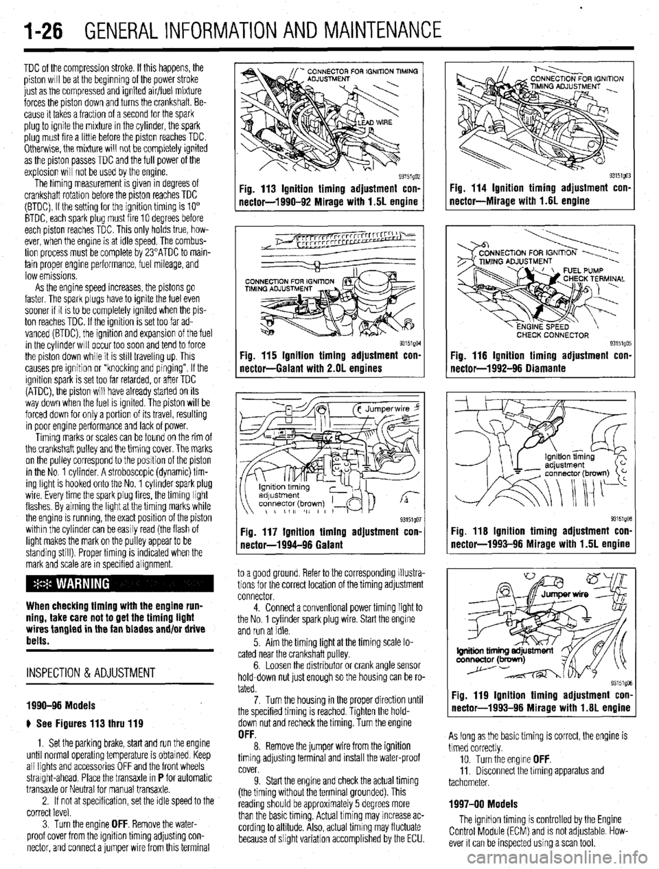
e See Figures 113 thru 119
1. Set the parking brake, start and run the engine
until normal operating temperature is obtained. Keep
all lights and accessories OFF and the front wheels
straight-ahead. Place the transaxle in
P for automatic
transaxle or Neutral for manual transaxle.
2. If not at specification, set the idle speed to the
correct level.
3. Turn the engine
OFF. Remove the water-
proof cover from the igmtion timing adjusting con-
nector, and connect a jumper wire from this terminal
Fig. 113 Ignition timing adjustment con-
nector-1990-92 Mirage with 1.5L engine
93151QM Fig. 115 Ignition timing adjustment con-
nectar-Galant with 2.OL engines
93151QO1 Fig. 117 Ignition timing adjustment con.
nectar-1994-96 Galant
to a good ground. Refer to the corresponding illustra-
tions for the correct location of the timing adjustment
connector.
4. Connect a conventional power timing light to
the No. 1 cylinder spark plug wire. Start the engine
and run at idle.
5. Aim the timing light at the timing scale lo-
cated near the crankshaft pulley.
6. Loosen the distributor or crank angle sensor
hold-down nut just enough so the housing can be ro-
tated.
7. Turn the housing in the proper direction until
the specified timing is reached. Tighten the hold-
down nut and recheck the timing. Turn the engine
OFF. 8. Remove the jumper wire from the ignition
timing adjusting terminal and install the water-proof
cover.
9. Start the engine and check the actual timing
(the timing without the terminal grounded). This
reading should be approximately 5 degrees more
than the basic timing. Actual timing may increase ac-
cording to altitude. Also, actual timing may fluctuate
because of slight variation accomplished by the ECU.
Fig. 114 Ignition timing adjustment con-
nectar-Miracle with 1.6L enaine
CHECK CONNECTOR 93151QO! Fig. 116 Ignition timing adjustment con.
nectar-1992-96 Oiamante
93151gOB Fig. 116 Ignition timing adjustment con-
nector-1993-96 Mirage with 1.5L engine
Fig. 119 Ignition timing adjustment con-
nector-1993-96 Mirage with 1.6L engine
As long as the basic timing is correct, the engine is
timed correctly.
10. Turn the engine
OFF. 11. Disconnect the timing apparatus and
tachometer.
1997-00 Models
The ignition timing is controlled by the Engine
Control Module (ECM) and is not adjustable. How-
ever it can be inspected using a scan tool.
Page 26 of 408
GENERALINFORMATIONAND MAlNTENANdE I-27
ADJUSTMENT
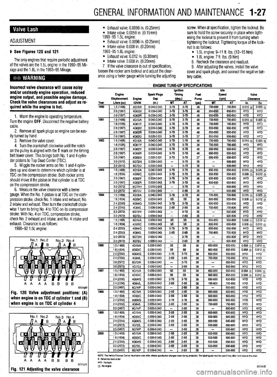
u See Figures 120 and 121
The only engines that require periodic adjustment
of the valves are the 1.5L engine in the 1990-95 Mi-
rage and the 1.8L in the 1993-95 Mirage.
Incorrect valve clearance will cause noisy
and/or unsteady engine operation, reduced
engine output, and possible engine damage.
Check the valve clearances and adjust as re-
quired while the engine is hot.
1. Warm the engine to operating temperature.
Turn the engine OFF. Disconnect the negative battery
cable.
2. Remove all spark plugs so engine can be eas-
ily turned by hand
3. Remove the valve cover.
4. Turn the crankshaft clockwise until the notch
on the pulley is aligned with the
T mark on the timing
belt lower cover. This brings both No. 1 and 4 cylin-
der pistons to Top Dead Center (TDC).
5. Wiggle the rocker arms on No. 1 and 4 cylin-
ders up and down to determine which cylinder is at
TDC on the compression stroke. Both rocker arms
should move if the piston in that cylinder is at TDC
on the compression stroke.
6. Measure the valve clearance with a feeler
gauge. When the No. 1 piston is at TDC on the com-
pression stroke, check No. 1 intake and
exhaust; No.
2 intake and exhaust. Then turn the crankshaft clock-
wise 1 turn to bring No. 4 to TDC on its compression
stroke. With No. 4 on TDC, compression stroke,
check No. 2 exhaust and intake; and No. 4 intake and
exhaust. Clearance is as follows:
1990-92 1.5L engine:
No.1 No.2
No.3 No.4
when engine is on TDC of cylinder 1 and (B) when engine is on TDC of cylinder 4
No.1 No.2
No.3 No.4
AA AA BB BB
93151g10 Fig. 121 Adjusting the valve clearance
l Exhaust valve: 0.0098 in. (0.25mm) screw. When at specification, tighten the locknut. Be l Intake valve: 0.0059 in. (0.15mm)
1993-95 1.5L engine: sure to hold the screw securely in place when tight-
l Exhaust valve: 0.0098 in. (0.25mm) ening the locknut to prevent it from turning when
* Intake valve: 0.008 in. (0.20mm) tightening the locknut. Tightening torque of the lock-
nut is as follows:
1993-95 1.8L engine:
l Exhaust valve: 0.012 in. (0.30mm) l 1.5L engine: 9-11 ft. Ibs. (12-15 Nm)
l Intake valve: 0.008 in. (0.20mm) l 1.8L engine: 7 ft. Ibs. (9 Nm)
8. Recheck the clearance and readjust.
7. If the valve clearance is out of specification,
9. After adjusting the valves, install the valve
loosen the rocker arm locknut and adjust the clear-
ante using a feeler gauge while turning the adjusting cover and spark plugs, and connect the negative bat-
tery cable.
Engine
ENGINE TUNE-UP SPECIFICATIONS Ignition
Spark Plugs liming
Fuel Idle
Speed Valve
Displacement
Engine
Gap (as.) Pump (rpm)
Clearance
Page 62 of 408
ENGINE MECHANICAL 3-1
ENGINE 3-1
REMOVAL &INSTALLATION 3-l
ROCKERARM(VALVE)COVER 3-l
REMOVAL &INSTALLATION 3-l
ROCKER ARM/SHAFTS 3-4
REMOVAL & INSTALLATION 3-4
THERMOSTAT 3-7
REMOVAL & INSTALLATION 3-7
INTAKE MANIFOLD 3-7
REMOVAL & INSTALLATION 3-7
EXHAUSTMANIFOLD 3-14
REMOVAL &INSTALLATION 3-14
TURBOCHARGER 3-17
REMOVAL & INSTALLATION 3-17
RADIATOR 3-18
REMOVAL & INSTALLATION 3-18
ENGINE FAN 3-19
REMOVAL &INSTALLATION 3-19
WATER PUMP 3-20
REMOVAL & INSTALLATION 3-20
CYLINDER HEAD 3-23
REMOVAL &INSTALLATION 3-23
OIL PAN 3-30
REMOVAL & INSTALLATION 3-30
OIL PUMP 3-33
REMOVAL &INSTALLATION 3-33
CRANKSHAFT DAMPER 3-36
REMOVAL &INSTALLATION 3-36
TIMING COVERAND BELT 3-36
REMOVAL & INSTALLATION 3-36
INSPECTION 3-48
FRONT CRANKSHAFTSEAL 3-48
REMOVAL & INSTALLATION 3-48
CAMSHAFT,BEARlNGSAND
LIFTERS 3-48
REMOVAL & INSTALLATION 3-48
INSPECTION 3-53
BALANCE SHAFT 3-54
REMOVAL &INSTALLATION 3-54
REAR MAIN SEAL 3-54
REMOVAL&INSTALLATION 3-54
FLYWHEEL/DRIVEPLATE 3-55
REMOVAL &INSTALLATION 3-55
EXHAUST SYSTEM 3-55
INSPECTION 3-55
REPLACEMENT 3-56
ENGINE RECONDITIONING 3-57
DETERMINIG ENGINE CONDITION 3-57
COMPRESSION TEST 3-57
OIL PRESSURETEST 3-57
BUYOR REBUILD? 3-57
ENGINE OVERHAULTIPS 3-58
TOOLS 3-58
OVERHAULTIPS 3-58
CLEANING 3-58
REPAIRING DAMAGEDTHREADS 3-59
ENGINE PREPARATION 3-59
CYLINDER HEAD 3-60
DISASSEMBLY 3-60
INSPECTION 3-
REFINISHING & REPAIRING 3-63 ASSEMBLY 3-64
ENGINE BLOCK 3-65
GENERALINFORMAITON 3-65
DISASSEMBLY 3-65
INSPECTION 3-65
REFINISHING 3-67
ASSEMBLY 3-67
ENGINE START-UP AND BREAK-IN 3-
STARTING THE ENGINE 3-69
BREAKING IT IN 3-69
KEEP IT MAINTAINED 3-69
SPECIFICATIONS CHARTS
ENGINE MECHANICAL
SPECIFICATIONS 3-70
TORQUE SPECIFICATIONS 3-81 .69
Page 63 of 408
3-2 ENGINEANDENGINEOVERHAUL
REMOVAL &INSTALLATION
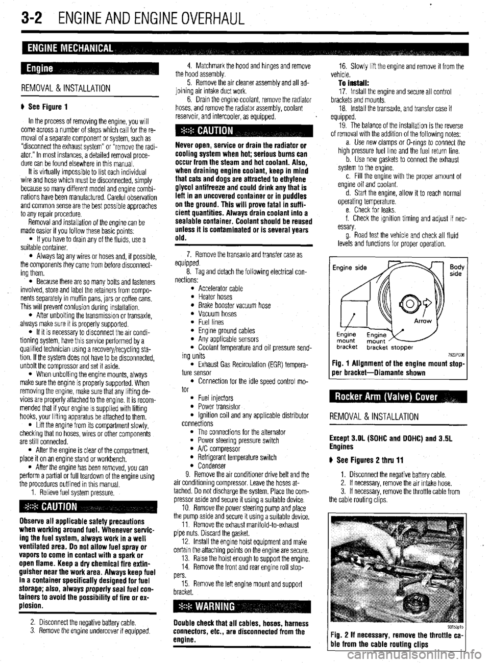
# See Figure 1
In the process of removing the engine, you will
come across a number of steps which call for the re-
moval of a separate component or system, such as
“disconnect the exhaust system” or “remove the radi-
ator.” In most instances, a detailed removal proce-
dure can be found elsewhere in this manual.
It is virtually impossible to list each individual
wire and hose which must be disconnected, simply
because so many different model and engrne combi-
nations have been manufactured Careful observation
and common sense are the best possible approaches
to any repair procedure.
Removal and installation of the engine can be
made easier if you follow these basic points:
l If you have to drain any of the fluids, use a
suitable container.
l Always tag any wires or hoses and, if possrble,
the components they came from before disconnect-
ing them.
l Because there are so many bolts and fasteners
involved, store and label the retainers from compo-
nents separately in muffin pans, jars or coffee cans.
This will prevent confusion during installatron.
l After unbolting the transmisston or transaxle,
always make sure it is properly supported.
l If it is necessary to disconnect the air condi-
tioning system, have this service performed by a
qualified technician using a recovery/recycling sta-
tion If the system does not have to be disconnected,
unbolt the compressor and set it aside.
l When unbolting the engine mounts, always
make sure the engine is properly supported. When
removing the engine, make sure that any lifting de-
vices are properly attached to the engine. It is recom-
mended that if your engine IS supplied with lifting
hooks, your lifting apparatus be attached to them.
l Lift the engine from its compartment slowly,
checking that no hoses, wires or other components
are still connected.
l After the engine is clear of the compartment,
place it on an engine stand or workbench.
l After the engine has been removed, you can
perform a partial or full teardown of the engine using
the procedures outlined in this manual.
1. Relieve fuel system pressure.
Observe all applicable safety precautions
when working around fuel. Whenever servic-
ing the fuel system, always work in a well
ventilated area. Do not allow fuel spray or
vapors to come in contact with a spark or
open flame. Keep a dry chemical fire extin-
guisher near the work area. Always keep fuel
in a container specifically designed for fuel
storage; also, always properly seal fuel con-
tainers to avoid the possibility of fire or ex-
plosion.
2. Disconnect the negative battery cable.
3. Remove the engine undercover if equipped. 4. Matchmark the hood and hinges and remove
the hood assembly.
5. Remove the air cleaner assembly and all ad-
joining air intake duct work.
6. Drain the engine coolant, remove the radiator
hoses, and remove the radiator assembly, coolant
reservoir, and intercooler, as equipped.
cooling system when hot; serious burns can
occur from the steam and hot coolant. Also,
when draining engine coolant, keep in mind
that cats and dogs are attracted to ethylene
glycol antifreeze and could drink any that is
left in an uncovered container or in puddles
on the ground. This will prove fatal in suffi-
cient quantities. Always drain coolant into a
sealable container. Coolant should be reused
unless it is contaminated or is several years
old.
7. Remove the transaxle and transfer case as
equipped.
8. Tag and detach the following electrical con-
nections:
l Accelerator cable l Heater hoses l Brake booster vacuum hose l Vacuum hoses l Fuel lines l Engine ground cables l Any applicable sensors l Coolant temperature and oil pressure send-
ing units
l Exhaust Gas Recirculation (EGR) tempera-
ture sensor
l Connection for the idle speed control mo-
tor
l Fuel injectors l Power transistor l Ignition coil and any applicable distributor
connections
l The connections for the alternator l Power steering pressure switch l A/C compressor l Refrigerant temperature switch l Condenser
9. Remove the air conditioner drive belt and the
air conditioning compressor. Leave the hoses at-
tached. Do not discharge the system. Place the com-
pressor aside and secure it using a suitable device.
10. Remove the power steering pump and place
the pump asrde and secure it using a surtable device.
11. Remove the exhaust manifold-to-exhaust
pipe nuts. Discard the gasket.
12. Install the engine hoist equipment and make
certain the attaching points on the engine are secure.
13. Raise the hoist enough to support the engine.
14. Remove the front and rear engine roll stop-
pers
15. Remove the left engine mount and support
Double check that all cables, hoses, harness
connectors, etc., are disconnected from the
engine.
16. Slowly lift the engine and remove it from the
vehicle.
To install:
17. Install the engine and secure all control
brackets and mounts.
18. Install the transaxle, and transfer case if
equipped.
19. The balance of the installation is the reverse
of removal with the addition of the following notes:
a. Use new clamps or O-rings to connect the
high pressure fuel lme and the fuel return line.
b. Use new gaskets to connect the exhaust
system to the engine.
c. Fill the engine with the proper amount of
engine oil and coolant.
d. Start the engine, allow it to reach normal
operating temperature.
e. Check for leaks.
f. Check the ignition timing and adjust if nec-
essary.
g. Road test the vehicle and check all fluid
levels and functions for proper operation.
Fig. 1 Alignment of the engine mount stop-
oer bracket-Diamante shown
REMOVAL &INSTALLATION
Except 3.OL (SOHC and DOHC) and 3.5L
Engines
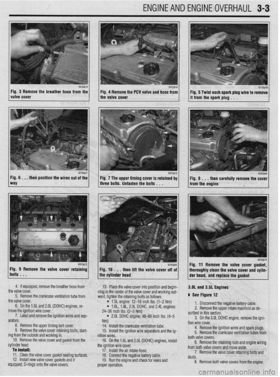
# See Figures 2 thru 11
1. Disconnect the negative battery cable.
2. If necessary, remove the air intake hose.
3. If necessary, remove the throttle cable from
the cable routing clips.
Fig. 2 If necessary, remove the throttle ca-
ble from the cable routing clips
Page 64 of 408
ENGINEANDENGINEOVERHAUL 3-3
Fig. 3 Remove the
breather hose from the Fig. 4 Remove the PCW valve
and hose from
93153p17 Fig. 6 . . . then position the wires out of the
Fig. 7 The upper timing cover is retained by
three bolts. Unfasten the bolts . . . Fig. 8 . . . then carefully remove the cover
from the engine
Fig. 9 Remove the valve cover retaini
then lift the valve cover
4. If equipped, remove the breather hose from
13.
the valve cover. Place the valve cover into position and begin-
5. Remove the crankcase ventilation tube from ning in the center of the valve cover and working out-
the valve cover. ward, tighten the retaining bolts as follows:
6. On the 1.6L and 2.gL (DOHC) engines, re-
l 15L engine: 12-18 inch Ibs. (l-2 Nm)
move the ignition wire cover. l 1.6L, 1.8L, 2.OL DOHC, and 2.4L engines:
7. Label and remove the ignition wires and sep- 24-36 inch Ibs. (2-3 Nm)
arators. * 2.OL SOHC engine: WO inch Ibs. (4-5
8. Remove the upper timing belt cover. Nm)
14. Install the crankcase ventilation tube.
9. Remove the valve cover retaining bolts, start
15.
ing from the outside and working in. Install the ignition wire separators and the ig-
nition wires.
10. Remove the valve cover and gasket from the
16.
cylinder head. On the 1.6L and 2.OL (DOHC) engines, install
the ignition wire cover.
To install:
17. Install the air intake hose.
11. Clean the valve cover gasket sealing surfaces,
12, Install new valve cover gaskets and if 18. Connect the negative battery cable.
equipped, O-rings onto the valve covers. 19. Run the engine and check for leaks and
proper operation. 3.OL and 3.5L Engines
b See Figure 12
1. Disconnect the negative battery cable.
2. Remove the upper intake manifold as de-
scribed in this section.
3. On the 3.OL DOHC engine, remove the igni-
tion wire cover.
4. Remove the ignition wires and spark plugs.
5. Remove the crankcase ventilation tubes from
both valve covers.
6. Remove the retaining nuts and engine wiring
from both valve covers and move aside.
7. Remove the valve cover retaining bolts and
studs.
8. Remove both valve covers from the engine.
Page 66 of 408
ENGINEANDENGINEOVERHALJL 3-5
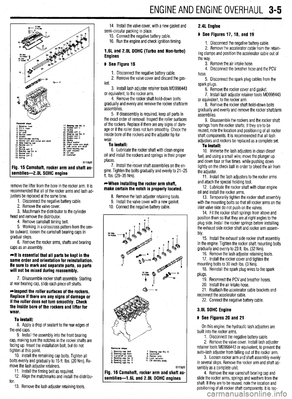
Fig. 15 Camshaft, rocker arm and shaft as-
remblies-2.01 SOHC engine
remove the lifter from the bore in the rocker arm. It is
recommended that all of the rocker arms and lash ad-
justers be replaced at the same time.
1. Disconnect the negative battery cable.
2. Remove the valve cover.
3. Matchmark the distributor to the cylinder
head and remove the distributor.
4. Remove camshaft timing belt.
5. Working in a crisscross pattern from the cen-
ter outward, loosen the camshaft bearing caps in
gradual steps.
6. Remove the rocker arms, shafts and bearing
caps as an assembly.
*It is essential that all parts be kept in the
same order and orientation for reinstallation.
Be sure to mark and separate parts, so parts
will not be mixed during reassembly.
7. Disassemble rocker shaft assembly. Starting
at rear bearing cap, slide each piece off shafts.
*Inspect the roller surfaces of the rockers.
Replace if there are any signs of damage or
if the roller does not turn smoothly. Check
the inside bore of the rockers and lifter for
wear.
To install:
8. Apply a drop of sealant to the rear edges of
the end caps.
9. Install the assembly into the front bearing
cap, making sure the notches in the rocker shafts are
facing up. Insert the installation bolt, but do not
tighten at this point.
10. Install the remaining cap bolts. Tighten all
bolts evenly and gradually to 15 ft. Ibs. (20 Nm). Re-
move the lash adjuster retainers.
11. Install the timing belt as required.
12. Align the matchmarks and install the distribu-
tor.
13. Remove the lash adjuster retaining tools. 14. Install the valve cover, with a new gasket and
semi-circular packing in place.
15. Connect the negative battery cable.
16. Run the engine and check ignition timing.
1.6L and 2.OL DOHC (Turbo and Non-turbo)
Engines
6 See Figure 16
1. Disconnect the negative battery cable.
2. Remove the valve cover and discard the gas-
ket.
3. Install lash adjuster retainer tools MD998443
or equivalent, to the rocker arm.
4. Remove the rocker shaft hold-down bolts
gradually and evenly and remove the rocker shaft/arm
assemblies.
5. If disassembly is required, keep all parts in
the exact order of removal. Inspect the roller surfaces
of the rockers. Replace if there are any signs of dam-
age or if the roller does not turn smoothly. Check the
inside bore of the rockers and the adjuster tip for
wear.
To install: 6. Lubricate the rocker shaft with clean engine
oil and install the rockers and springs in their proper
places.
7. Install the rocker shaft assemblies on the en-
gine. Tighten the bolts gradually and evenly to 21-25
ft. Ibs. (29-35 Nm).
*When installing the rocker arm shaft,
make certain the notch is properly located.
8. Remove the lash adiuster retainina tools
9. Install the valve cover with a new gasket.
10. Connect the negative battery cable.
F :ig. 16 Camshaft, rocker arm and shaft as
s iemblies-1.6L and 2.OL DOHC engines
*o Nm
IILlbs -
9315390 3
2.4L Engine
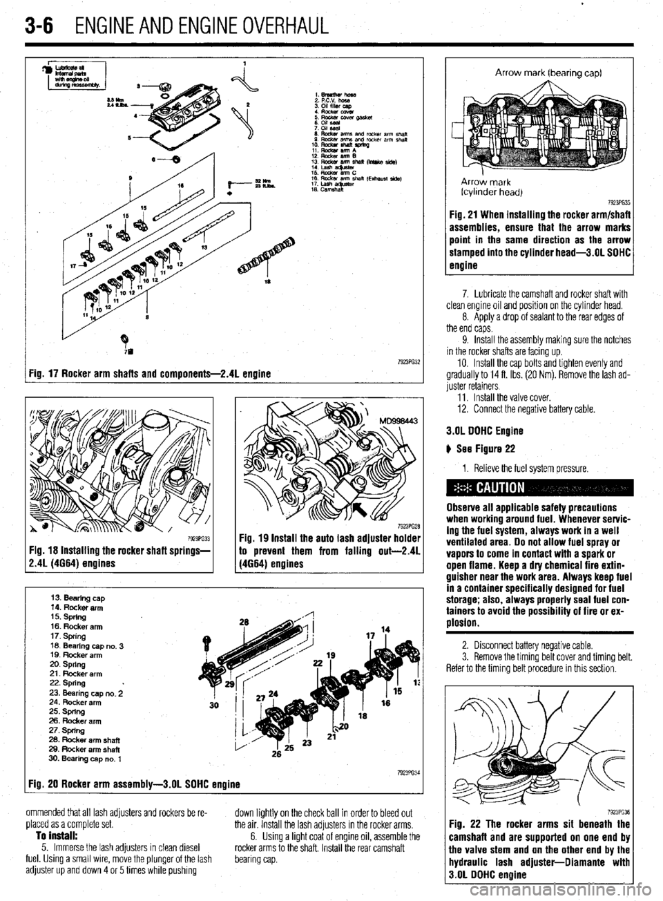
# See Figures 17, 16, and 19
1. Disconnect the negative battery cable.
2. Remove the accelerator cable from the retain-
ing clamps and position the accelerator cable out of
the way.
3. Remove the air intake hose.
4. Disconnect the breather hose and the PCV
hose.
5. Disconnect the spark plug cables from the
spark plugs.
6. Remove the rocker cover and gasket.
7. Install lash adjuster retainer tools MD998443
or equivalent, to the rocker arm.
8. Remove the rocker shaft hold-down bolts
gradually and evenly and remove the rocker shaft/arm
assemblies.
9. Disassemble the rockers and the rocker shaft
springs from the rocker shafts. If they are to be
reused, note the location and positionrng of all rocker
shaft components. It is recommended that all lash
adjusters and rockers be replaced as a complete set.
To install: 10. Immerse the lash adjusters in clean diesel
fuel, and using a small wire, move the plunger up
and down four or five times. while pushing down
lightly on the check ball in order to bleed the air from
the adjuster.
11. Install the lash adjusters to the rocker arms
and attach the special holding tool.
12. Lubricate the rocker shaft with clean engine
oil and install the rocker arms.
13. Temporarily tighten the rocker shaft assembly
with the mounting bolts so that all rocker arms on the
inlet valve side do not push on the valves,
14. Fit the rocker shaft springs from above and
position them so that they are at right angles to the
plug side. Install the rocker springs before installing
the exhaust side rocker shaft and rocker arm assem-
bly.
15. Install the exhaust side rocker shaft assembly
in the engine. Tighten the rocker shaft mounting bolts
gradually and evenly to 23 ft. Ibs. (32 Nm).
16. Remove the lash adjuster retaining tools.
17. Install the rocker cover and tighten the
mounting bolts to 30 inch Ibs. (3 Nm).
18. Reinstall the spark plug wires to the spark
plugs.
19. Reconnect the PCV and breather hoses.
20. Install the air intake hose.
21. Reattach the accelerator cable brackets and
reconnect the accelerator cable.
22. Connect the negative battery cable.
3.OL SOHC Engine
6 See Figures 20 and 21
On this engine, the hydraulic lash adjusters are
built into the rocker arms,
1. Disconnect the negative battery cable.
2. Remove the valve cover. Install lash adjuster
retainer tools MD998443 or equivalent, to prevent the
auto-lash adjuster from falling out of the rocker arm.
3. Loosen rocker arm and shaft assembly evenly
in several steps. Remove the rocker arm and shaft as-
sembly as a complete unit.
4. Remove the rear camshaft bearing cap and
slide the rocker arms, springs and washers from the
shaft. If they are to be reused, note the location and
positioning of all rocker shaft components. It is rec-
Page 67 of 408
.
3-6 ENGINEANDENGINEOVERHAUL
I Fig. 17 Rocker arm shafts and components-2.41 engine
Fig. 18 Installing the rocker shaft springs- 79231632
13. Bearing cap
14. Rocker arm
15. spring
16. Rocker arm
17. Spring
16 Bearing no. cap 3
IQ. Rocker arm
20. spring
21. Rocker arm
22. Spring
23. Bearing no. cap 2
24. Rocker arm
25. spring
26. Rocker arm
27. Spring
28. Rocker arm shaft
29. Rocker arm shaft
30. Bearing no. cap 1
Fig. 20 Rocker arm assembly-3.01 SOHC engine 7923PG3
ommended that all lash adjusters and rockers be re-
placed as a complete set.
To install:
5. Immerse the lash adjusters in clean diesel
fuel. Using a small wire, move the plunger of the lash
adjuster up and down 4 or 5 times while pushing down lightly on the check ball in order to bleed out
the air. Install the lash adjusters in the rocker arms.
6. Using a light coat of engine oil, assemble the
rocker arms to the shaft. Install the rear camshaft
bearing cap.
Arrow mark (bearing cap)
Arrow mark
fcyllnder head)
7923PG35 Fig. 21 When installing the rocker arm/shafi
assemblies, ensure that the arrow marks
point in the same direction as the arrow
stamped into the cylinder head-3.01 SOHC
engine
7. Lubricate the camshaft and rocker shaft with
clean engine oil and position on the cylinder head.
8. Apply a drop of sealant to the rear edges of
the end caps.
9. Install the assembly making sure the notches
in the rocker shafts are facing up.
10. Install the cap bolts and tighten evenly and
gradually to 14 ft. Ibs. (20 Nm). Remove the lash ad-
juster retainers
11. Install the valve cover.
12. Connect the negative battery cable.
3.OL OOHC Engine
) See Figure 22
1. Relieve the fuel system pressure.
Observe all applicable safety precautions
when working around fuel. Whenever servic-
ing the fuel system, always work in a well
ventilated area. 00 not allow fuel spray or
vapors to come in contact with a spark or
open flame. Keep a dty chemical fire extin-
guisher near the work area. Always keep fuel
in a container specifically designed for fuel
storage; also, always properly seal fuel con-
tainers to avoid the possibility of fire or ex-
plosion.
2. Disconnect battery negative cable.
3. Remove the timino belt cover and timina belt.
Refer to the timing belt procedure in this section.
7923PG3 Fig. 22 The rocker arms sit beneath the
camshaft and are supported on one end bl
the valve stem and on the other end by the
hydraulic lash adjuster-Oiamante wit1
3.OL OOHC engine
Page 68 of 408
ENGINEANDENGINEOVERHAUL 3-7
4. Remove the center cover, breather and PCV
hoses, and spark plug cables.
5. Remove the rocker cover.
6. Remove the throttle body stay, both camshaft
sprockets, and oil seals.
7. Remove the Camshaft Position fCMP) sensor 3. install the lash adjuster clips on the rocker
arms, then loosen the bearing cap bolts. Do not re-
move the bolts from the bearing caps.
4. Remove the rocker arms, shafts and bearing
caps as an assembly.
lo hlstall: unless it is contaminated or is several years old.
3. Remove any necessary components to access
the thermostat.
4. Remove the thermostat housinq retaininq
nd adapter from the rear of the camshah. ’
8. Remove the intake and exhaust camshafts.
9. Remove rocker arms and lash adjusters from
he head. It is recommended that all lash adjusters
md rockers be replaced as a complete set.
To Install:
10. Immerse the lash adjusters in clean diesel
uel. Using a small wire, move the plunger of the lash
tdjuster up and down four or five times while push-
ng down lightly on the check ball in order to bleed
jut the air. Lubricate and install the lash adjusters in
he cylinder head.
11. Lubricate the camshafts with clean enqine oil
nd position the camshafts on the cylinder head.
12. Install the bearing caps. Tighten the caps in
sequence, in 2 or 3 steps. Caps 2,3 and 4 have a
ront mark. Install with the mark aligned with the front
nark on the cylinder head. Intake caps have I
stamped on the cap and exhaust caps have E. Also,
)e sure the rocker arm is correctly mounted on the
ash adjuster and the valve stem end. Torque the front
md rear retaining cap bolts to 14 ft. Ibs. (20 Nm) and
ighten the center 3 retaining cap bolts to 8 ft. Ibs.
11 Nm).
13. Apply a coating of engine oil to the oil seals
md install.
14. Install the timing belt, valve cover and all re-
ated parts. Refer to the timing belt procedure in this
;ection. 5. Install the bearing caps/rocker arm assem-
blies. Tighten the bolts to 23 ft. Ibs. (31 Nm).
6. Remove the lash adjuster clips.
7. Install the rocker arm cover using a new gas-
ket.
8. Connect the negative battery cable.
REMOVAL &INSTALLATION
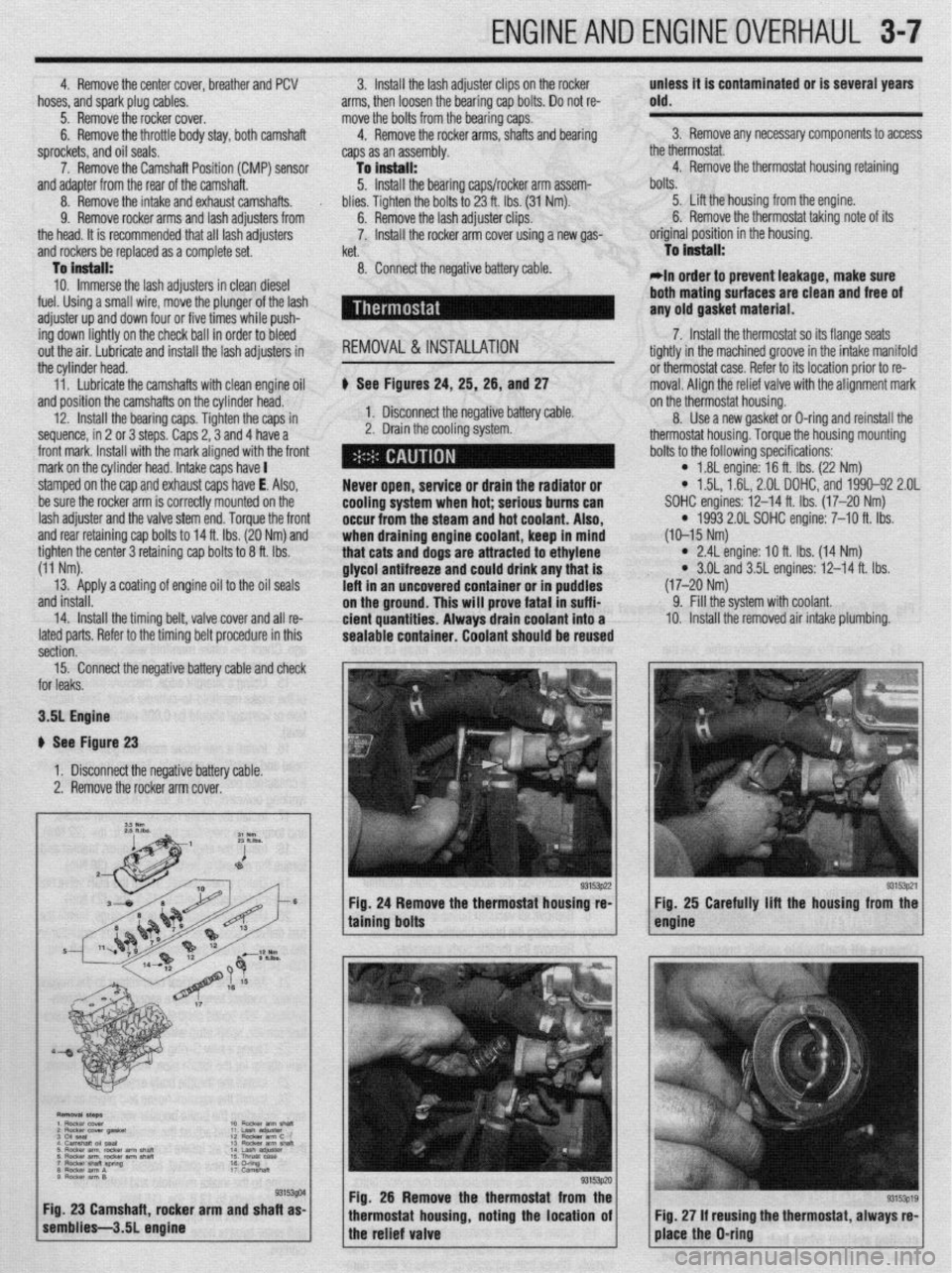
b See Figures 24, 25, 26, and 27
1. Disconnect the negative battery cable.
2. Drain the cooling system.
Never open, service or drain the radiator or
cooling system when hot; serious bums can
occur from the
steam and hot coolant. Also,
when draining engine coolant, keep in mind
that cats and dogs are attracted to ethylene
glycol antifreeze and could drink any that is
left in an uncovered container or in puddles
on the ground. This will prove fatal in suffi-
cient quantities. Always drain coolant into a
sealable container. Coolant should be reused bolts.
5. Lift the housing from the engine.
6. Remove the thermostat taking note of its
original position in the housing.
To Install:
*In order to prevent leakage, make sure
both mating
surfaces are clean and free of
any old gasket material.
7. Install the thermostat so its flange seats
tightly in the machined groove in the intake manifold
or thermostat case. Refer to its location prior to re-
moval. Aliqn the relief valve with the alignment mark
on the thermostat housing.
8. Use a new gasket or D-ring and reinstall the
thermostat housing. Torque the housing mounting
bolts to the following specifications:
l 1.8L engine: 16 ft. Ibs. (22 Nm) l 1.5L, 1.61, 2.OL DOHC, and 1990-92 2.OL
SOHC engines: 12-14 ft. Ibs. (17-20 Nm)
l 1993 2.01 SOHC engine: 7-10 ft. Ibs.
(10-15 Nm)
l 2.4L engine: IO ft. Ibs. (14 Nm) l 3.OL and 3.5L engines: 12-14 ft. Ibs.
(17-20 Nm)
9. Fill the system with coolant.
10. Install the removed air intake plumbing.
15. Connect the negative battery cable and check
or leaks.
3.51 Engine
I See Figure 23
1. Disconnect the negative battery cable.
2. Remove the rocker arm cover.
g. 26 Remove the thermostat from the
ousing, noting the location of using the thermostat, always re-