brake pads replacement MITSUBISHI DIAMANTE 1900 Repair Manual
[x] Cancel search | Manufacturer: MITSUBISHI, Model Year: 1900, Model line: DIAMANTE, Model: MITSUBISHI DIAMANTE 1900Pages: 408, PDF Size: 71.03 MB
Page 2 of 408

.
1-2 GENERALINFORMATIONAND MAINTENANCE
Chitton’s Total Car Care manual for the 199M10
Mitsubishi Mirage, Galant and Diamante is intended
to help you learn more about the inner workings of
your vehicle while saving you money on its upkeep
and operation.
The beginning of the book will likely be referred to
the most, since that is where you will find information
for maintenance and tune-up. The other sections deal
with the more complex systems of your vehicle. Oper-
ating systems from engine through brakes are cov-
ered to the extent that the average do-it-yourselfer be-
comes mechanically involved. This book will not
explain such things as rebuilding a differential for the
simple reason that the expertise required and the in-
vestment in special tools make this task uneconomi-
cal. It will, however, give you detailed instructions to
help you change your own brake pads and shoes, re-
place spark plugs, and perform many more jobs that
can save you money, give you personal satisfaction
and help you avoid expensive problems.
A secondary purpose of this book is a reference for
owners who want to understand their vehicle and/or
their mechanics better. In this case, no tools at all are
required.
Before removing any bolts, read through the entire
procedure. This will give you the overall view of what
tools and supplies will be required. There is nothing
more frustrating than having to walk to the bus stop
on Monday morning because you were short one bolt
on Sunday afternoon. So read ahead and plan ahead.
Each operation should be approached logically and
all procedures thoroughly understood before attempt-
ing any work.
All sections contain adjustments, maintenance, re-
moval and installation procedures, and in some cases,
repair or overhaul procedures. When repair is not con-
sidered practical, we tell you how to remove the part
and then how to install the new or rebuilt replacement.
In this way, you at least save labor costs. “Backyard”
repair of some components is just not practical.
Many procedures in this book require you to “label
and disconnect. . ” a group of lines, hoses or wires.
Don’t be lulled into thinking you can remember where
everything goes-you won’t. If you hook up vacuum
or fuel lines incorrectly, the vehicle may run poorly, if
at all. If you hook up electrical wiring incorrectly, you
may instantly learn a very expensive lesson.
You don’t need to know the official or engineering
name for each hose or line. A piece of masking tape
on the hose and a piece on its fitting will allow you to
assign your own label such as the letter A or a short name. As long as you remember your own code, the
lines can be reconnected by matching similar letters
or names. Do remember that tape will dissolve in
gasolrne or other fluids; if a component is to be
washed or cleaned, use another method of identifica-
tion. A permanent felt-tipped marker or a metal scribe
can be very handy for marking metal parts. Remove
any tape or paper labels after assembly.
It’s necessary to mention the difference between
maintenance and repair Maintenance includes rou-
tine inspections, adjustments, and replacement of
parts which show signs of normal wear Maintenance
compensates for wear or deterioration. Repair implies
that something has broken or is not working. A need
for repair is often caused by lack of maintenance. Ex-
ample, draining and refilling the automatic transaxle
fluid is maintenance recommended by the manufac-
turer at specific mileage intervals. Failure to do this
can shorten the life of the transmission/transaxle, re-
quiring very expensive repairs. While no maintenance
program can prevent items from breaking or wearing
out, a general rule can be stated: MAINTENANCE IS
CHEAPER THAN REPAIR.
Two basic mechanrc’s rules should be mentioned
here. First, whenever the left side of the vehicle or en-
gine is referred to, it is meant to specify the drivers
side. Conversely, the right side of the vehicle means
the passengers side. Second, screws and bolts are
removed by turning counterclockwise, and tightened
by turning clockwrse unless specifically noted.
Safety is always the most important rule. Con-
stantly be aware of the dangers involved in working
on an automobile and take the proper precautions.
See the informatron in this section regarding SER-
VICING YOUR VEHICLE SAFELY and the SAFETY
NOTICE on the acknowledgment page.
Pay attention to the instructions provided. There
are 3 common mistakes in mechanical work:
1. Incorrect order of assembly, disassembly or
adjustment. When taking something apart or putting
it together, performing steps in the wrong order usu-
ally just costs you extra time; however, it CAN break
something. Read the entire procedure before begin-
ning disassembly. Perform everything in the order in
which the instructions say you should, even if you
can’t immedrately see a reason for it. When you’re
taking apart something that is very intricate, you
might want to draw a picture of how it looks when as-
sembled at one point in order to make sure you get everything back in its proper position. We will supply
exploded views whenever possible. When making
adjustments, perform them in the proper order. One
adjustment possibly will affect another.
2. Overtorquing (or undertorquing). While it is
more common for overtorquing to cause damage,
undertorquing may allow a fastener to vibrate loose
causing serious damage. Especially when dealing
with aluminum parts, pay attention to torque specifi-
cations and utilize a torque wrench in assembly. If a
torque figure is not available, remember that if you
are using the right tool to perform the job, you will
probably not have to strain yourself to get a fastener
tight enough. The pitch of most threads is so slight
that the tension you put on the wrench will be multi-
plied many times in actual force on what you are
tightening. A good example of how critical torque is
can be seen in the case of spark plug installation, es-
pecially where you are putting the plug into an alu-
minum cylinder head. Too little torque can fail to
crush the gasket, causing leakage of combustion
gases and consequent overheating of the plug and
engine parts. Too much torque can damage the
threads or distort the plug, changing the spark gap.
There are many commercial products available for
ensuring that fasteners won’t come loose, even if they
are not torqued just right (a very common brand is
Loctite? If you’re worried
about getting something
together tight enough to hold, but loose enough to
avoid mechanical damage during assembly, one of
these products might offer substantial insurance. Be-
fore choosing a threadlocking compound, read the
label on the package and make sure the product is
compatible with the materials, fluids, etc. involved.
3. Crossthreading. This occurs when a part such
as a bolt is screwed into a nut or casting at the wrong
angle and forced. Crossthreading is more likely to
occur if access is difficult. It helps to clean and lubri-
cate fasteners, then to start threading the bolt, spark
plug, etc. with your fingers If you encounter resis-
tance, unscrew the part and start over again at a dif-
ferent angle until it can be inserted and turned several
times without much effort. Keep in mind that many
parts, especially spark plugs, have tapered threads,
so that gentle turning will automatically bring the part
you’re threading to the proper angle. Don’t put a
wrench on the part until its been tightened a couple
of turns by hand. If you suddenly encounter resis-
tance, and the part has not seated fully, don’t force it.
Pull it back out to make sure it’s clean and threading
properly.
Be sure to take your time and be patient, and al-
ways plan ahead. Allow yourself ample time to per-
form repairs and maintenance You may find main-
taining your car a satisfying and enjoyable
experience.
b See Figures 1 thru 15
Naturally, without the proper tools and equipment
it is impossible to properly service your vehicle. It
would also be virtually impossible
to catalog every
tool that you would need to perform all of the opera-
tions in this book. Of course, It would be unwise for
the amateur to rush out and buy an expensive set of
tools on the theory that he/she may need one or more
of them at some time, The best approach is to proceed slowly, gathering savings will
be far outweighed by frustration and
a good quality set of those tools that are used most mangled knuckles.
frequently Don’t be misled by the low cost of bargain Begin accumulating those tools that are used most
tools. It is far better to spend a little more for better frequently: those associated with routine maintenance
quality. Forged wrenches, 6 or 12-point sockets and and tune-up. In addition to the normal assortment of
fine tooth ratchets are by far preferable to their less screwdrivers and pliers, you should have the follow-
expensive counterparts. As any good mechanic can ing tools:
tell you, there are few worse experiences than trying
l Wrenches/sockets and combination open
to work on a vehicle with bad tools. Your monetary end/box end wrenches in sizes from %-% in. or
Page 323 of 408

SUSPENSION AND STEERING 8-27
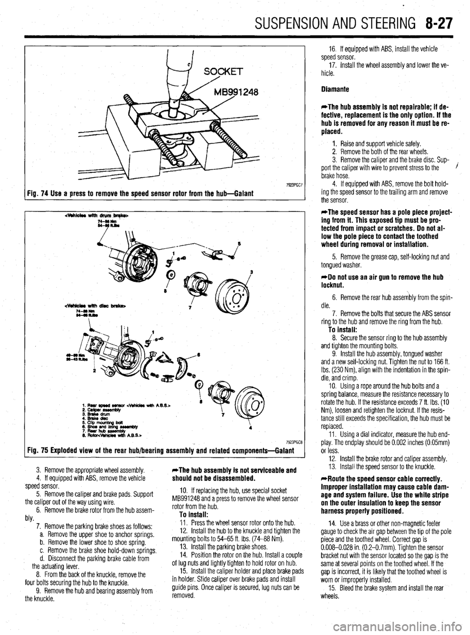
7923PGC7 Fig. 74 Use a press to remove the speed sensor rotor from the hub-Galant
dhk4w with drum,brqb
7923PGCE Fig. 75 Exploded view of the rear hub/bearing assembly and related components=Galant
3. Remove the appropriate wheel assembly. *The hub assembly is not serviceable and 4. If equipped with ABS, remove the vehicle should not be disassembled. speed sensor.
5. Remove the caliper and brake pads, Support
the caliper out of the way using wire.
6. Remove the brake rotor from the hub assem-
hl
10. If replacing the hub, use special socket
MB991248 and a press to remove the wheel sensor
rotor from the hub.
To install: WY. 7. Remove the parking brake shoes as follows:
a. Remove the upper shoe to anchor springs.
b. Remove the lower shoe to shoe spring.
c. Remove the brake shoe hold-down springs.
d. Disconnect the parking brake cable from
the actuating lever.
8. From the back of the knuckle, remove the
four bolts securing the hub to the knuckle.
9. Remove the hub and bearing assembly from
the knuckle. Il. Press the wheel sensor rotor onto the hub.
12. Install the hub to the knuckle and tighten the
mounting bolts to 54-65 ft. tbs. (74-88 Nm).
13. Install the parking brake shoes,
14. Position the rotor on the hub. Install a couple
of lug nuts and lightly tighten to hold rotor on hub.
15. Install the caliper holder and place brake pads
in holder. Slide caliper over brake pads and install
guide pins. Once caliper is secured, lug nuts can be
removed. 16. If equipped with ABS, install the vehicle
speed sensor.
17. Install the wheel assembly and lower the ve-
hicle.
Diamante
*The hub assembly is not repairable; if de-
fective, replacement is the only option. If the
hub is removed for any reason it must be re-
placed.
1. Raise and support vehicle safely.
2. Remove the both of the rear wheels.
3. Remove the caliper and the brake disc. Sup-
port the caliper with wire to prevent stress to the /
brake hose.
4. If equipped with ABS, remove the bolt hold-
ing the speed sensor to the trailing arm and remove
the sensor.
*The speed sensor has a pole piece project-
ing from it. This exposed tip must be pro-
tected from impact or scratches. Do not al-
low the pole piece to contact the toothed
wheel during removal or installation.
5. Remove the grease cap, self-locking nut and
tongued washer.
*Do not use an air gun to remove the hub
locknut.
6. Remove the rear hub assembly from the spin-
dle.
7. Remove the bolts that secure the ABS sensor
ring to the hub and remove the ring from the hub.
To install: 8. Secure the sensor ring to the hub assembly
and tighten the mounting bolts.
9. Install the hub assembly, tongued washer
and a new self-locking nut. Tighten the nut to 166 ft.
Ibs. (230 Nm), align with the indentation in the spin-
dle, and crimp.
IO. Using a rope around the hub bolts and a
spring balance, measure the resistance necessary to
rotate the hub. If the resistance exceeds 7 ft. Ibs. (IO
Nm), loosen and retighten the locknut. If the resis-
tance still exceeds the specification, the hub must be
replaced.
11. Using a dial indicator, measure the hub end-
play. The endplay should be 0.002 inches (0.05mm)
or less.
12. Install the brake rotor and caliper assembly.
13. Install the speed sensor to the knuckle.
*Route the speed sensor cable correctly.
Improper installation may cause cable dam-
age and system failure. Use the white stripe
on the outer insulation to keep the sensor
harness properly positioned.
14. Use a brass or other non-magnetic feeler
gauge to check the air gap between the tip of the pole
piece and the toothed wheel. Correct gap is
0.008-0.028 in (0.2-0.7mm). Tighten the sensor
bracket nut with the sensor located so the gap is the
same at several points on the toothed wheel. If the
gap is incorrect, it is likely that the toothed wheel is
worn or improperly installed.
15. Bleed the brake system and install the rear
wheels.
Page 393 of 408

TROUBLESHOOTlNGll-11
b. Driveshaft misaligned. Check for collapsed or damaged engine and transmission
mounts, and replace as necessary.
c. Driveshaft bent or out of balance. Replace damaged components and reinstall.
d. Driveshaft out of balance. Remove the driveshaft and have it balanced by a competent
professional, or replace the driveshaft assembly.
NOTE: Most driveshafts are linked together by universal joints; however,
some manufacturers use Constant Velocity (CV) joints or rubber flex cou-
plers.
All Wheel and Four Wheel Drive Vehicles
1. Front or rear wheel makes a clicking noise
a. Check for debris such as a pebble, nail or glass in the tire or tire tread. Carefully re-
move the debris. Small rocks and pebbles rarely cause a puncture; however, a sharp
object should be removed carefully at a facility capable of performing tire repairs.
b. Check for a loose, damaged or worn Constant Velocity (CV) joint and replace if defec-
tive.
2. Front or rear wheel vibrates wlth Increased speed
a. Check for a bent rim and replace, if damaged.
b. Check the tires for balance or internal damage and replace if defective.
c. Check for a loose, worn or damaged wheel bearing and replace if defective.
d. Check for a loose, damaged or worn Constant Velocity (CV) joint and replace if defec-
tive.
Front Wheel Drive Vehicles
3. Front wheel makes a c&kin@ noise
a. Check for debris such as a pebble, nail or glass in the tire or tire tread. Carefully re-
move the debris. Small rocks and pebbles rarely cause a puncture; however, a sharp
object should be removed carefully at a facility capable of performing tire repairs.
b. Check for a loose, damaged or worn Constant Velocity (CV) joint and replace if defec-
tive. 4. Rear wheel makes a clicking noise
a. Check for debris such as a pebble, nail or glass in the tire or tire tread. Carefully re-
move the debris. Small rocks and pebbles rarely cause a puncture; however, a sharp
object should be removed carefully at a facility capable of performing tire repairs.
Rear Wheel Drive Vehicles
5. Front or rear wheel makes a clicking noise
a. Check for debris such as a pebble, nail or glass in the tire or tire tread. Carefully re-
move the debris. Small rocks and pebbles rarely cause a puncture; however, a sharp
object should be removed carefully at a facility capable of performing tire repairs.
6. Rear wheel shudders or vibrates
a. Check for a bent rear wheel or axle assembly and replace defective components.
b. Check for a loose, damaged or worn rear wheel bearing and replace as necessary.
1. Burning odor from center of vehicle when accelerating
a. Check for a seizing brake hydraulic component such as a brake caliper. Check the
caliper piston for surface damage such as rust, and measure for out-of-round wear
and caliper-to-piston clearance. For additional information on brake related odors, re-
fer to section 3-A, condition number 9.
b. On vehicles with a manual transmission, check for a slipping clutch. For possible
causes and additional information, refer to section Z-C, condition number 1.
c. On vehicles with an automatic transmission, check the fluid level and condition, Top
off or change the fluid and filter using the recommended replacement parts, lubricant
type and amount. If the odor persists, transmission removal and disassembly will be
necessary.
2. Engine accelerates, but vehicle does not gain speed
a. On vehicles with a manual transmission, check for a slipping or damaged clutch. For
possible causes and additional information refer to section Z-C, condition number 1.
b. On vehicles with an automatic transmission, check the fluid level and condition. Top
off or change the fluid and filter using the recommended replacement parts, lubricant
type and amount. If the slipping continues, transmission removal and disassembly will
be necessary.
1. Brake pedal pulsates or shimmies when pressed
a. Check wheel lug nut torque and tighten evenly to specification.
b. Check the brake rotor for trueness and thickness variations. Replace the rotor if it is
too thin, warped, or if the thickness varies beyond specification. Some rotors can be
machined: consult the manufacturer’s specifications and recommendations before us-
ing a machined brake rotor.
c. Check the brake caliper or caliper bracket mounting bolt torque and inspect for loose-
ness. Torque the mounting bolts and inspect for wear or any looseness, including
worn mounting brackets, bushings and sliding pins.
d. Check the wheel bearing for looseness. If the bearing is loose, adjust if possible, oth-
erwise replace the bearing.
2. Brakes make a squealing noise
a. Check the brake rotor for the presence of a ridge on the outer edge; if present, remove
the ridge or replace the brake rotor and brake pads.
b. Check for debris in the brake lining material, clean and reinstall.
c. Check the brake linings for wear and replace the brake linings if wear is approaching
the lining wear limit.
d. Check the brake linings for glazing. Inspect the brake drum or rotor surface and re-
place, along with the brake linings, if the surface is not smooth or even.
e. Check the brake pad or shoe mounting areas for a lack of lubricant or the presence of
surface rust. Clean and lubricate with a recommended high temperature brake grease.
3. Brakes make a flrindinfl noise
a. Check the brake linings and brake surface areas for severe wear or damage. Replace
worn or damaged parts.
b. Check for a seized or partially seized brake causing premature or uneven brake wear,
excessive heat and brake rotor or drum damage. Replace defective parts and inspect
the wheel bearing condition, which could have been damaged due to excessive heat.
4. Vehicle pulls to one side during braking
a. Check for air in the brake hydraulic system. Inspect the brake hydraulic seals, fluid
lines and related components for fluid leaks. Remove the air from the brake system by bleeding the brakes. Be sure to use fresh brake fluid that meets the manufacturers rec-
ommended standards.
b. Check for an internally restricted flexible brake hydraulic hose. Replace the hose and
flush the brake system.
c. Check for a seizing brake hydraulic component such as a brake caliper. Check the
caliper piston for surface damage such as rust, and measure for out-of-round wear
and caliper-to-piston clearance. Overhaul or replace failed parts and flush the brake
system.
d. Check the vehicle’s alignment and inspect for suspension wear. Replace worn bush-
ings, ball joints and set alignment to the manufacturers specifications.
e. If the brake system uses drum brakes front or rear, check the brake adjustment. Inspect
for seized adjusters and clean or replace, then properly adjust.
5. Brake pedal feels spongy or has excessive travel
a. Check the brake fluid level and condition. If the fluid is contaminated or has not been
flushed every two years, clean the master cylinder reservoir, and bleed and flush the
brakes using fresh brake fluid that meets the manufacturers recommended standards.
b. Check for a weak or damaged flexible brake hydraulic hose. Replace the hose and
flush the brake system.
c. If the brake system uses drum brakes front or rear, check the brake adjustment. Inspect
for seized adjusters and clean or replace, then properly adjust.
6. Brake pedal feel is firm, but brakes lack sufficient stopping power or
fade
a. Check the operation of the brake booster and brake booster check valve: Replace worn
or failed parts.
b. Check brake linings and brake surface areas for glazing and replace worn or damaged
parts.
c. Check for seized hydraulic parts and linkages, and clean or replace as needed.
7. Vehicle has excessive front end dive or locks rear brakes too easily
a. Check for worn, failed or seized brake proportioning valve and replace the valve.
b. Check for a seized, disconnected or missing spring or linkage for the brake propor-
tioning valve. Replace missing parts or repair as necessary.
Page 404 of 408

11-22 MASTER INDEX
REMOVAL&INSTALLATION 9-3
BRAKE MASTERCYLINDER I-41
FLUIDRECOMMENDATIONS 1-41
LEVELCHECK I-41
BRAKE OPERATING SYSTEM B-2
BRAKEPADS 9-8
INSPECTION 9-11
REMOVAL & INSTALLATION 9-8
'
BRAKESHOES 9-16
ADJUSTMENTS 9-18
INSPECTION 9-16
REMOVAL&INSTALLATION 9-17
BRAKESHOES 9-23
ADJUSTMENT 9-24
REMOVAL & INSTALLATION 9-23
BUY OR REBUILD? 3-57
CABLE(S) 9-20
ADJUSTMENT 9-22
REMOVAL & INSTALLATION 9-20
CAMSHAFT POSITIONSENSOR 4-14
OPERATION 4-14
REMOVAL &INSTALLATION 4-14
TESTING 4-14
CAMSHAFT, BEARINGSAND LIFTERS 3-48
INSPECTION 3-53
REMOVAL & INSTALLATION 3-48
CENTERBEARING 7-15
REMOVAL & INSTALLATION 7-15
CHARGING SYSTEM 2-8
CHASSISGREASING l-43
CAR WASHING 1-43
INTERIOR CLEANING l-44
WAXING l-43
CIRCUIT BREAKERS 6-28
CIRCUIT PROTECTION 6-27
CLEARING CODES 4-27
CLEARING CODES 4-28
WITHASCANTOOL 4-28
WITHOUTASCANTOOL 4-28
CLUTCH CABLE 7-9
ADJUSTMENT 7-9
REMOVAL AND INSTALLATION 7-9
CLUTCH MASTER CYLINDER 7-9
REMOVALANDINSTALLATION 7-9
CLUTCHSLAVECYLINDER 7-9
HYDRAULIC SYSTEM BLEEDING 7-9
REMOVAL &INSTALLATION 7-9
CLUTCH 7-7
CLUTCHMASTERCYLINDER l-42
FLUIDRECOMMENDATIONS l-42
LEVELCHECK l-42
COMBINATION SWITCH 8-29
REMOVAL &INSTALLATION 8-29
COMPONENTLOCATIONS 4-16
CONTROL CABLES 6-12
ADJUSTMENT 6-12
CONTROL PANEL 6-12
REMOVAL&INSTALLATION 6-12
COOLINGSYSTEM l-39
DRAIN &REFILL I-40
FLUIDRECOMMENDATIONS l-39
FLUSHINGANDCLEANING THESYST
EM-41
LEVELCHECK l-39
TESTING FOR LEAKS l-39
CRANKCASEVENTILATIONSYSTEM 4-2
COMPONENTTESTING 4-2
OPERATION 4-2
REMOVAL &INSTALLATION 4-2
CRANKSHAFTDAMPER 3-36 REMOVAL &INSTALLATION 3-36
CRANKSHAFTANDCAMSHAFTPOSITIONSENSORS 2-7
CRANKSHAFTANDCAMSHAFTPOSITIONSENSORS 2-5
CRANKSHAFTPOSlTlONSENSOR/CRANKANGLESENSOR 4-14
OPERATION 4-14
REMOVAL&INSTALLATION 4-15
TESTING 4-15
CRUISE CONTROL 6-13
CV-BOOTS I-21
INSPECTION I-21
CYLINDER HEAD 3-23
REMOVAL & INSTALLATION 3-23
CYLINDER HEAD 3-60
DETERMINIG ENGINE CONDITION 3-57
COMPRESSION TEST 3-57
OIL PRESSURETEST 3-57
DIAGNOSIS AND TESTING 9-24
DIAGNOSISANDTESTING 2-2
DIAGNOSISANDTESTING 2-5
DIAGNOSTICTROUBLECODES 4-27
DIAGNOSTICTROUBLECODES 4-28
FLASH OUTCODELIST 4-32
DIMMER SWITCH 6-19
REMOVAL &INSTALLATION 6-19
DISC BRAKES 9-8
DISCONNECTING THE CABLES 6-7
DISTRIBUTOR IGNITION SYSTEM 2-2 f
DISTRIBUTOR 2-4
INSTALLATION 2-4
REMOVAL&INSTALLATION 2-4
DISTRIBUTORCAPANDROTOR l-25
INSPECTION l-25
REMOVAL&INSTALLATION l-25
DISTRIBUTORLESS IGNITION SYSTEM 2-5
DO'S l-4
DON'TS l-6
DOORGLASSANDREGULATOR lo-10
REMOVAL &INSTALLATION IO-IO
DOOR HANDLE/LATCHASSEMBLY IO-IO
REMOVAL & INSTALLATION IO-IO
DOORLOCKCYLINDER IO-IO
REMOVAL & INSTALLATION IO-IO
DOOR PANELS IO-7
REMOVAL & INSTALLATION IO-7
DOORS IO-2
REMOVAL &INSTALLATION IO-2
DRlVEAXLE(AWD GALANTONLY) l-10
DRIVELINE 7-14
DRIVEN DISC AND PRESSURE PLATE 7-7
DRIVESHAFTAND U-JOINTS 7-14
DRIVESHAFT BALANCING 7-15
REMOVAL & INSTALLATION 7-14
U-JOINTREPLACEMENT 7-14
DRUM BRAKES 9-15
ELECTRIC WINDOW MOTOR IO-IO
REMOVAL &INSTALLATION IO-IO
ELECTRICALCOMPONENTS 6-2
CONNECTORS 6-4
GROUND 6-3
LOAD 6-3
POWERSOURCE 6-2
PROTECTIVE DEVICES 6-3
SWITCHES&RELAYS 6-3
WIRING & HARNESSES 6-3
ELECTRONIC ENGINE CONTROLS 4-7
EMISSION CONTROLS 4-2
ENGINE BLOCK 3-65
ASSEMBLY 3-67
DISASSEMBLY 3-65