hood release MITSUBISHI DIAMANTE 1900 Repair Manual
[x] Cancel search | Manufacturer: MITSUBISHI, Model Year: 1900, Model line: DIAMANTE, Model: MITSUBISHI DIAMANTE 1900Pages: 408, PDF Size: 71.03 MB
Page 214 of 408
CHASSIS ELECTRICAL 6-11
45. Install the heater hoses under the hood.
46. Install the mstrument panel by reversing its
removal procedure.
47. Install the center console.
48. install the upper and lower steering column
covers.
49. Install the center panel undercover.
50. Install the small column panel.
51. Install the steering wheel.
52. Fill the cooling system.
53. Connect the negative battery cable and check
the entire climate control system for proper operation
and leaks.
Mirage
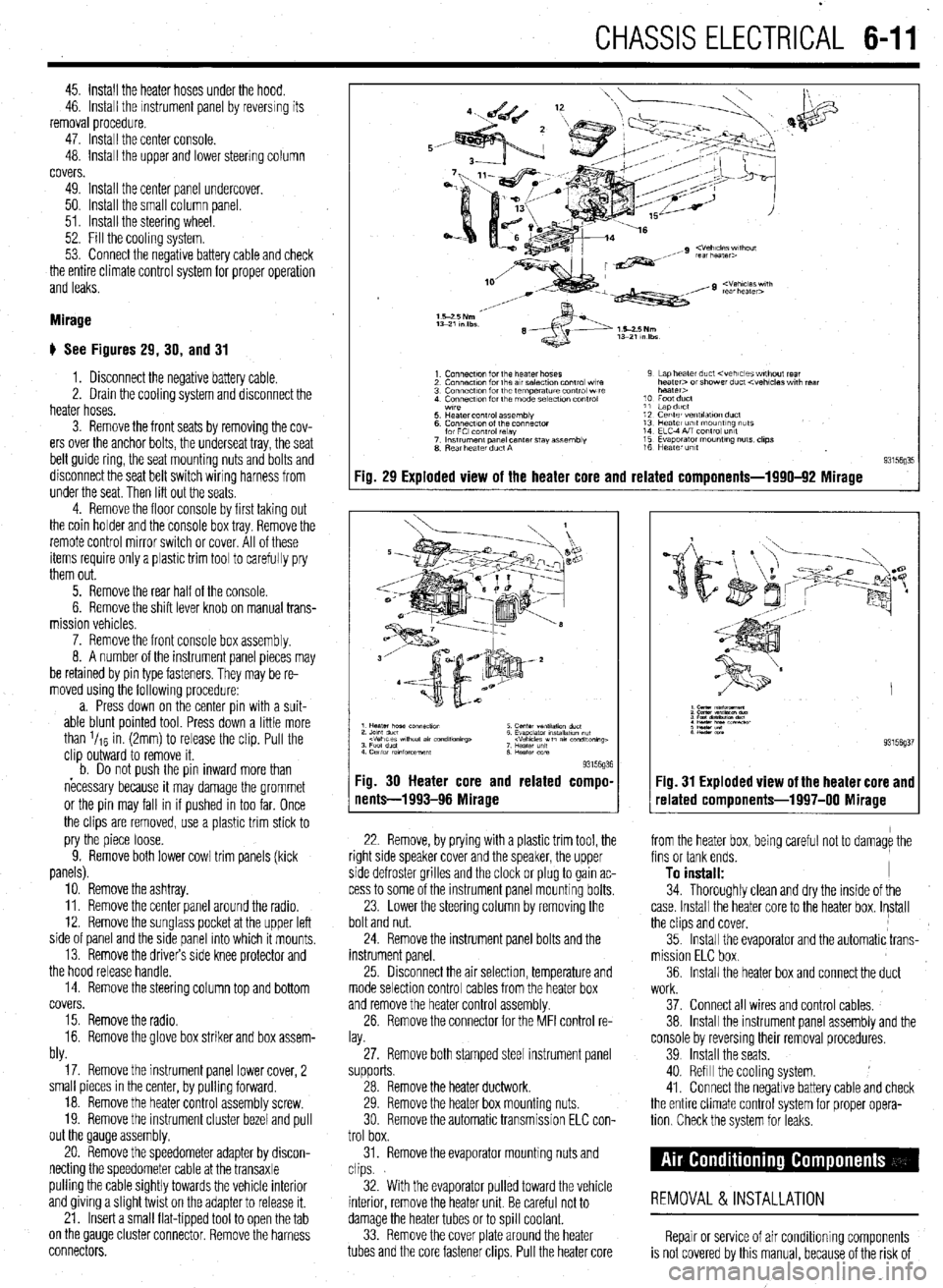
# See Figures 29, 30, and 31
1. Disconnect the negative battery cable.
2. Drain the cooling system and disconnect the
heater hoses.
3. Remove the front seats by removing the cov-
ers over the anchor bolts, the underseat tray, the seat
belt guide ring, the seat mounting nuts and bolts and
disconnect the seat belt switch wiring harness from
under the seat. Then lift out the seats
4. Remove the floor console by first taking out
the coin holder and the console box tray. Remove the
remote control mirror switch or cover. All of these
items require only a plastic trim tool to carefully pry
them out.
5. Remove the rear half of the console.
6. Remove the shift lever knob on manual trans-
mission vehicles.
7. Remove the front console box assembly.
8. A number of the instrument panel pieces may
be retamed by pin type fasteners. They may be re-
moved using the following procedure:
a. Press down on the center pin with a suit-
able blunt pointed tool. Press down a little more
than l/re in. (2mm) to release the clip. Pull the
clip outward to remove it.
b. Do not oush the oin inward more than
necessary because it may damage the grommet
or the pin may fall in if pushed in too far. Once
the clips are removed, use a plastic trim stick to
pry the piece loose.
9. Remove both lower cowl trim panels (kick
panels).
10. Remove the ashtray.
11. Remove the center panel around the radio.
12. Remove the sunglass pocket at the upper left
side of panel and the side panel into which it mounts,
13. Remove the drivers side knee protector and
the hood release handle.
14. Remove the steering column top and bottom
covers.
15. Remove the radio.
16. Remove the glove box striker and box assem-
bly.
17. Remove the instrument panel lower cover, 2
small pieces in the center, by pulling forward.
18. Remove the heater control assembly screw.
19. Remove the instrument cluster bezel and pull
out the Qauge assembly.
20. Remove the speedometer adapter by discon-
necting the speedometer cable at the transaxle
pulling the cable Sightly towards the vehicle interior
and giving a Slight twist on the adapter to release it.
21. Insert a small flat-tipped tool to open the tab
on the QauQe cluster connector. Remove the harness
connectors.
Fig. 29 Exploded view of the heater core and related components-1990-92 Mirage
93l%Q% Fig. 30 Heater core and related compo-
nents-1993-96 Mirage
22. Remove, by prying with a plastic trim tool, the
right side speaker cover and the speaker, the upper
side defroster grilles and the clock or plug to gain ac-
cess to some of the instrument panel mounting bolts.
23. Lower the steering column by removing the
bolt and nut.
24. Remove the instrument panel bolts and the
instrument panel.
25 Drsconnect the air selection, temperature and
mode selection control cables from the heater box
and remove the heater control assembly.
26. Remove the connector for the MFI control re-
lay.
27. Remove both stamped steel instrument panel
supports.
28. Remove the heater ductwork.
29. Remove the heater box mounting nuts.
30 Remove the automatic transmission ELC con-
trol box.
31. Remove the evaporator mounting nuts and
clips.
32. With the evaporator pulled toward the vehicle
interior, remove the heater unit. Be careful not to
damage the heater tubes or to spill coolant.
33. Remove the cover plate around the heater
tubes and the core fastener clips. Pull the heater core 34. Thoroughly clean and dry the inside of the
case. Install the heater core to the heater box. Install
the clips and cover,
35. Install the evaporator and the automatic trans-
mission ELC box.
36. Install the heater box and connect the duct
Fig. 31 Exploded view of the heater core and
related components-1997-00 Mirage
from the heater box, being careful not to damage the
fins or tank ends.
To install: I
work.
37. Connect all wires and control cables,
38. Install the instrument panel assembly and the
console by reversmg their removal procedures.
39 Install the seats.
40. Refill the cooling system.
41. Connect the negative battery cable and check
the entire climate control system for proper opera-
tion Check the system for leaks.
REMOVAL &INSTALLATION
Repair or service of air Conditioning components
is not covered by this manual, because of the risk of
Page 220 of 408
CHASSIS ELECTRICAL 647
3. Remove the windshield wiper arms by un-
screwing the cap nuts and lifting the arms from the
linkage posts.
4. Remove the front deck garnish assembly.
Iver.
xl harness plug from
,I6 #-n\,LIr 5. Remove the air inlet c(
6. Disconnect the electric
the wiper motor.
7. Remove the access ho,, LIVIGil. To install:
5. Install the motor and install the retaining bolts.
6. Install the wiper arm so that the arm is 3.35
inches (85mm) between the measurement points,
when parked. Secure the wiper arm with the retaining
nut.
*Before proceeding, connect the battery and
8. Remove the wiper motor mounting bolts.
9. Detach the motor crank arm from the wiper
linkane and remnve the mntnr
motor has been factory set. Do not remove
them unless necessary. if they must be re-
moved, remove them only after marking their
mounting positions. check the operation of the motor. if satisfae-
tory, disconnect the cable and complete the
installation.
o. WIIIIW LIE Il~&WVt: vatreryoable and recheck
the system for proper operation.
..-
a- - ‘- _ _ _ . _ _ _
*The installation angle of the crank arm and 7. Install the interior trim piece
n II ^_^^^ IAL- -^I-I:..- L-AL--
To install:
10. Install the windshield wiper motor and con-
REMOVAL&INSTALLATION nect the linkage.
I 14. Install the front deck garnish assembly. I. YIV”“I1IIYVL VI” “UyuL’.” “UL’“‘, UUUIU. 2. Remove the windshield washer fluid resarvnir
’ 11. Attach the electrical harness plug.
12. Install the access hole cover.
13. Install the air inlet cover.
15. Reinstall the wiper arm and tighten the
mounting nuts to 14 ft. Ibs. (19 Nm). Install the arms
so the blades are parallel to the garnish molding -
Front and Rear
1 nivnnnprt the nonatiua haltorv rahlo
3. Drain any washer fluid in the reservoir into an
appropriate container.
4.
I when parked. Remove the pump from the reservoir by either
16. Connect the neaative batterv cable and check removing the retaining hardware or twisting gently
tlntil it is frpp frnm thP rosorvnir the wiper system for proper operation.
lo Install:
5. Inspect the pump seal on the reservoir, replace
/ de&h the linkage Fig 59 Pull the motor from the firewaii and
“‘%‘y 1 ““I”“,,,,,, the if necessary.
1 1 Disconn& thP rwnativo hatton/ rahlm 6. Install the pump into place until seated on the .I,” ~‘“p.L’,” YULL”‘, -YI”. liftgate lower trim. seal.
3: Lift the smatr CUVBI, I~IIIUV~ tilt: lfAdllllll~ IIUL II --. .-- -^- ^..^ .L^ -_,_:..:-- -.A 7. Install the windshield washer fluid reservoir. 2. Matchmark the wirier arms tn the shaft and A Refill thp wxhpr fllk-l rpqprvnir markthe arms to the proper side for reinstallation and remove the wiper arm.
4. Remove the mountina bolts and remove the “. .,“...S .V.” ....“III. ,*..*” IYUY..“m,.
9. Connect the negative battery cable.
REMOVAL&INSTALLATION
tie interior, release the lock by turning the tie interior, release the lock by turning the
adapter to the right or left and remove the adapter to the rigM or left and remove the
adapter. adapter.
5. The installation is the reverse of the removal
6. The installation is the reverse of the removal
Mirage
1. Disconnect the negative battery cable. Remove
the center trim panel. procedure. Use care not to damage the printed circuit procedure. Use care not to damage the printed circuit
board or any gauge components.
board or any gauge components.
6. Connect the negative battery cable and check
7. Connect the negative battery cable and check
all cluster-related items for proper operation. i III cluster-related items for proper operation.
2. Remove the knee protector. If pin type clips are
used, they may be removed using the following pro-
cedure:
a. Press down on the center pin with a suit-
able blunt pointed tool. Press down a little more
than ‘IIS in. (2mm). This releases the clip. Pull
the clip outward to remove it.
b. Do not push the pin inward more than
necessary because it may damage the grommet
or the pin may fall in, if pushed in too far. Once
the clips are removed, use a plastic trim stick if
necessary to pry the knee protector loose.
3. Remove the instrument cluster bezel.
4. Remove the instrument cluster. Disassemble
and remove gauges or the speedometer as required.
*if the speedometer cable adapter requires
setvice, disconnect the cable at the transaxie
end. Pull the cable slightly toward the vehi- Gaiant
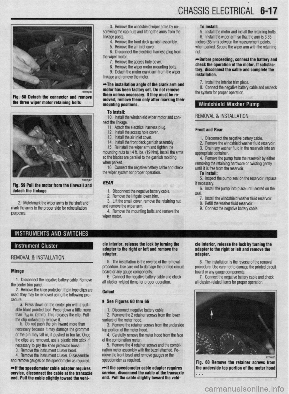
@ See Figures Bg thru 66
1. Disconnect negative battery cable.
2. Remove the 2 retainer screws from the lower
surface of the meter hood.
3. Remove the retainer screws from the underside
top portion of the meter hood.
4. Carefully remove the meter hood from the face
of the combination meter.
5. Remove the 4 retainer screws and the combi-
nation meter assembly with the bezel attached. Re-
move the front bezel and remove gauges or the
speedometer as required.
*if the speedometer cable adapter requires
service, disconnect the cable at the transaxie
end. Pull the cable slightly toward the vehi-
Page 221 of 408
.
6-18 CHASSIS ELECTRICAL
Fig. 64 Grasp the instrument cluster and
carefully pull it out of the instrument panel tached; the cluster has sockets on the back Fig. 66 . , .
these sockets engage connec-
tors solidly mounted behind the cluster
Diamante
1. Disconnect the negative battery cable.
*If equipped with an air bag, be sure to dis-
arm it before entering the vehicle.
2. Remove the hood lock release handle and
switches from the knee protector below the steering
column. Then remove the exposed retaining screws
and remove the knee protector.
3. Remove the upper and the lower steering col-
umn covers.
4. Remove the instrument cluster bezel.
5. Remove the instrument cluster. Disassemble
and remove gauges or the speedometer as required.
*If the speedometer cable adapter must be
serviced. disconnect the cable at the
transaxle end. Pull the cable slightly toward
the vehicle interior, release the lock by turn-
ing the adapter to the right or left and remove
the adapter.
6. The installation is the reverse of the removal
procedure. Use care not to damage the printed circuit
board or any gauge components,
7. Connect the negative battery cable and check
all cluster-related items for proper operation.
REMOVAL &INSTALLATION
I
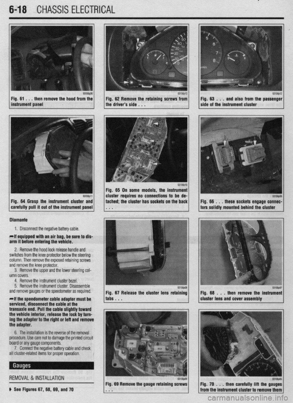
b See Figures 67, 66, 69, and 70
83156pD6 Fig. 69 Remove the gauge retaining screws Fig. 70 . . . then carefully lift the gauges
from the instrument cluster to remove them
Page 281 of 408
7-2 'DRIVETRAIN
Because of the way an internal combustron engine
breathes, it can produce torque, or twisting force,
only within a narrow speed range. Most modern,
overhead valve pushrod engines must turn at about
2500 rpm to produce their peak torque By 4500 rpm
they are producrng so lrttle torque that contrnued in-
creases in engine speed produce no power increases.
The torque peak on overhead camshaft engines IS
generally much higher, but much narrower.
The manual transaxle and clutch are employed to
vary the relationship between engine speed and the
speed of the wheels so that adequate engine power can
be produced under all crrcumstances. The clutch al-
lows engine torque to be applied to the transaxle input
shaft gradually, due to mechanical slippage. Conse-
quently, the vehicle may be started smoothly from a
full stop The transaxle changes the ratio between the
rotating speeds of the engine and the wheels by the
use of gears. The gear ratios allow full engine power to
be applied to the wheels during acceleration at low
speeds and at highway/passing speeds.
In a front wheel drive transaxle, power is usually
transmitted from the input shaft to a mainshaft or out-
put shaft located slightly beneath and to the side of
the input shaft. The gears of the mainshaft mesh with
gears on the input shaft, allowing power to be carried
from one to the other. All forward gears are in con-
stant mesh and are free from rotating with the shaft
unless the synchronizer and clutch IS engaged. Shaft-
ing from one gear to the next causes one of the gears
to be freed from rotating with the shaft and locks an-
other to it. Gears are locked and unlocked by internal
dog clutches which slide between the center of the
gear and the shaft. The forward gears employ syn-
chronizers; friction members which smoothly bring
gear and shaft to the same speed before the toothed
dog clutches are engaged.
SHIFT LINKAGE
1. Disconnect the shift linkage from the transaxle.
2. On the transaxle, put select lever in N and
move the shift lever in
4th gear. Depress the clutch,
if necessary, to shift.
3. Move the shift lever in the vehicle to the
4th gear position until it contacts the stop.
4. Turn the adjuster turnbuckle so the shift cable
eye aligns with the eye in the gear shift lever. When
installing the cable eye, make sure the flange side of
the plastic bushing at the shift cable end is on the
cotter pin side.
5 The cables should be adjusted so the clear-
ance between the shift lever and the 2 stoppers are
equal when the shift lever IS moved to 3rd and 4th
gear. Move the shift lever to each positron and check i
that the shifting is smooth
REMOVAL &INSTALLATION
1, Disconnect the negative battery cable 2. Remove any components necessary to access
the back-up light switch.
3. Unplug the back-up light switch connector.
4. Remove the switch from the case using the ap-
propriate size socket and drive tool.
To install: 5. Install the switch and tighten it to 22-25 ft. Ibs.
(30-35 Nm).
6. Attach the back-up light switch connector
7. Install any components removed to access the
back-up light switch
8. Connect the negative battery cable.
REMOVAL & INSTALLATION
Mirage
*If the vehicle is going to be roiled while the
halfshafts are out of the vehicle, obtain 2 outer
CV-joints or proper equivalent tools and install
to the hubs. If the vehicle is rolled without the
proper torque applied to the front wheel bear-
ings, the bearings will no longer be usable.
*The suspension components should not be
tightened until the vehicles weight is resting
on the ground.
1. Remove the battery and battery tray.
2. Remove the air cleaner assembly and vacuum
hoses.
3. Note the locations and disconnect the shifter
cables.
4. If equipped with 1.61 engine, remove the ten-
sion rod.
5. Detach the backup lamp switch connector,
speedometer cable connection and remove the starter
motor.
6. Raise the vehicle and support safely.
7. Remove the front wheels and the inner wheel
panels.
8. Remove the undercover and splash pan.
9. Drain the transaxle oil into a suitable con-
tainer
10. Support the engine and remove the cross-
member.
11. Remove the upper transaxle mounting bolt
and bracket.
12 Disconnect the stabilizer bar, tie rod ends and
the lower ball joint connections.
13 Remove the clutch release cylinder and clutch
oil line bracket. Do not disconnect the fluid lines and
secure the slave cylinder with wire.
14 Disconnect the clutch cable, if equipped with
cable controlled clutch system.
15. Remove the halfshafts by inserting a prybar
between the transaxle case and the driveshaft and
prying the shaft from the transaxle. Do not pull on the
driveshaft Doing so damages the inboard joint. Do
not insert the prybar so far the oil seal in the case is
damaged.
*It is not necessary to disconnect the half-
shafts from the steering knuckle. Remove the
shaft with the hub and knuckle as an assem-
bly. Tie the shafts aside. Note the circle clip
on the end of the inboard shafts should not
be reused.
16. Remove the bellhousing lower cover.
17 Remove the transaxle to engine bolts and
lower the transaxle from the vehrcle.
To install:
*When installing the transaxle, be sure to
align the splines of the transaxle with the
clutch disc.
18 Install the transaxle to the engine and install
the mounting bolts. Tighten the bolts to 31-40 ft. Ibs.
(43-55 Nm) on 1990-92 models and 35 ft. Ibs. (48
Nm) on 1993-00 models.
19 Install the bellhousing cover.
*When installing the halfshafts, use new
circlips on the axle ends. Care must be taken
to ensure that the oil seal lip of the transaxle
is not damaged by the serrated part of the
driveshaft.
20. Install and fully seat the halfshafts into the
transaxle.
21. Install the slave cylinder.
22. Connect the ball joints, tie rod ends and the
stabilizer bar connections.
23. Install the upper transaxle mounting bracket
and bolt.
24. Install the crossmember.
25. Install the undercover.
26. Install the upper transaxle-to-engine mount-
ing bolts, Tighten the bolts to 31-40 ft. Ibs. (43-55
Nm) on 199C-92 models and 35 ff. Ibs. (48 Nm) on
1993-00 models.
27. Install the starter motor.
28 Connect the backup light switch connector
and speedometer cable.
29 Connect and adjust the shifter cables.
30 Install the air cleaner assembly.
31. Install the front wheels.
32 Make sure the vehicle is level when refilling
the transaxle Use Hypoid gear oil or equivalent, GL-
4 or higher.
33. Connect the negative battery cable and check
the transaxle for proper operation. Make sure the re-
verse lights operate when in reverse.
Galant
1999-93 MODELS
rlf the vehicle is going to be rolled on its
wheels while the halfshafts are out of the ve-
hicle, obtain two outer CV-joints or proper
equivalent tools and install to the hubs. If the
vehicle is rolled without the proper torque
applied to the front wheel bearings, the bear-
ings will no longer be usable.
1. Remove the battery and the air intake hoses.
2. If equipped with Active-ECS, unplug the
compressor wiring.
3. Remove the auto-cruise actuator and under-
hood bracket, located on the passenger side inner
fender well.
4. Drain the transaxle and transfer case fluid, if
equipped, into a suitable waste container.
5. Remove the retainer bolt and pull the
speedometer cable from the transaxle assembly.
6. Remove the cotter pin securing the select and
shift cables and remove the cable ends from the
transaxle.
Page 288 of 408
DRIVETRAIN 7-9
*When adjusting the clutch pedal height or
the clutch pedal clevis pin play, be careful
not to push the pushrod toward the master
cylinder.
d. Check that when the clutch pedal is de-
pressed all the way, the interlock switch switches
over from ON to OFF.
ADJUSTMENT
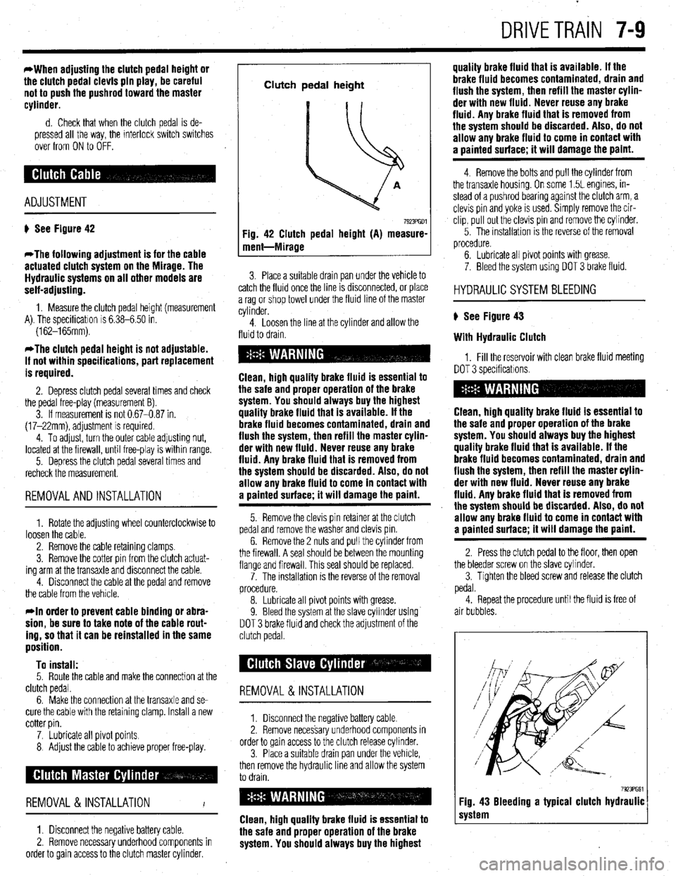
# See Figure 42
*The following adjustment is for the cable
actuated clutch system on the Mirage. The
Hydraulic systems on all other models are
self-adjusting.
1. Measure the clutch pedal height (measurement
A). The specificatron is 6.38-6.50 in.
(162-165mm).
*The clutch pedal height is not adjustable.
If not within specifications, part replacement
is required.
2. Depress clutch pedal several times and check
the pedal free-play (measurement B).
3. If measurement is not 0.67-0.87 in.
(17-22mm), adjustment is required.
4. To adjust, turn the outer cable adjusting nut,
located at the firewall, until free-play is within range.
5. Depress the clutch pedal several times and
recheck the measurement.
REMOVALANDINSTALLATION
1. Rotate the adjusting wheel counterclockwise to
loosen the cable.
2. Remove the cable retaining clamps.
3. Remove the cotter pin from the clutch actuat-
ing arm at the transaxle and disconnect the cable.
4. Disconnect the cable at the pedal and remove
the cable from the vehicle.
rln order to prevent cable binding or abra-
sion, be sure to take note of the cable rout-
ing, so that it can be reinstalled in the same
position.
To install:
5. Route the cable and make the connection at the
clutch pedal.
6. Make the connection at the transaxle and se-
cure the cable with the retaining clamp. Install a new
cotter pin.
7. Lubricate all pivot points.
8 Adjust the cable to achieve proper free-play.
REMOVAL &INSTALLATION
I
1. Disconnect the negative battery cable.
2. Remove necessary underhood components in
order to gain access to the clutch master cylinder.
Clutch pedal height
Fig. 42 Clutch pedal height (A) measure-
ment-Mirage
7923PGDl
3. Place a suitable drain pan under the vehicle to
catch the fluid once the line IS drsconnected, or place
a rag or shop towel under the fluid line of the master
cylinder.
4. Loosen the line at the cylinder and allow the
fluid to drain.
Clean, high quality brake fluid is essential to
the safe and proper operation of the brake
system. You should always buy the highest
quality brake fluid that is available. If the
brake fluid becomes contaminated, drain and
flush the system, then refill the master cylin-
der with new fluid. Never reuse any brake
fluid. Any brake fluid that is removed from
the system should be discarded. Also, do not
allow any brake fluid to come in contact with
a oainted surface; it will damage the paint.
5. Remove the clevis pin retainer at the clutch
pedal and remove the washer and clevis pm.
6. Remove the 2 nuts and pull the cylinder from
the firewall. A seal should be between the mounting
flange and firewall. This seal should be replaced.
7. The installation is the reverse of the removal
procedure.
8. Lubricate all pivot points with grease.
9. Bleed the system at the slave cylinder using
DOT 3 brake fluid and check the adjustment of the
clutch pedal.
REMOVAL &INSTALLATION
1. Disconnect the negative battery cable
2. Remove necessary underhood components in
order to gain access to the clutch release cylinder.
3. Place a suitable drain pan under the vehicle,
then remove the hydraulic line and allow the system
to drain.
Clean, high quality brake fluid is essential to
the safe and proper operation of the brake
system. You should always buy the highest quality brake fluid that is available. If the
brake fluid becomes contaminated, drain and
flush the system, then refill the master cylin-
der with new fluid. Never reuse any brake
fluid. Any brake fluid that is removed from
the system should be discarded. Also, do not
allow any brake fluid to come in contact with
a uainted surface; it will damage the paint.
4. Remove the bolts and pull the cylinder from
the transaxle housing. On some 1.5L engines, in-
stead of a pushrod bearing against the clutch arm, a
clevis pin and yoke is used. Simply remove the cir-
clip, pull out the clevis pin and remove the cylinder.
5. The installation IS the reverse of the removal
procedure.
6. Lubricate all pivot points with grease.
7. Bleed the system using DOT 3 brake fluid.
HYDRAULIC SYSTEM BLEEDING
) See Figure 43
With Hydraulic Clutch
1, Fill the reservoir with clean brake fluid meeting
DOT 3 specificatrons.
Clean, high quality brake fluid is essential to
the safe and proper operation of the brake
system. You should always buy the highest
quality brake fluid that is available. If the
brake fluid becomes contaminated, drain and
flush the system, then refill the master cylin-
der with new fluid. Never reuse any brake
fluid. Any brake fluid that is removed from
the system should be discarded. Also, do not
allow any brake fluid to come in contact with
a painted surface; it will damage the paint.
2. Press the clutch pedal to the floor, then open
the bleeder screw on the slave cvlinder.
3. Tighten the bleed screw and release the clutch
pedal.
4. Repeat the procedure until the fluid is free of
air bubbles.
7923PG91 Fig. 43 Bleeding a typical clutch hydraulic
system
Page 325 of 408
SUSPENSION AND STEERING 8-29
i ’
Do not hamme i4 l-ha nnlhnr !r on steering wheel to remove
,,. , II= ,,,,,,Jfble column mechanism may REMOVALANDINSTALLATION
I
be damaged.
To install:
ing
7.
6. Line up the matchmarks and install the steer-
/heel to the shaft.
Tighten the steering wheel attaching nut to
25-33 ft. Ibs. (35-45 Mm).
8. Attach the horn connector and install the horn
pad.
9. Connect the negative battery cable.
Diamante The air bag system (SRS or SIR) must be dis-
armed before removing the steering wheel.
Failure to do so may cause accidental de-
ployment, property damage or personal in-
MY.
1 Rscnnnnd the nnmtivn hattm rJhle . I._“” . ..I_. . ..I *.-~ _...” ““.‘“‘, _““._. 2. If equipped, disable the air bag system.
3. Remove the steering wheel as outlined earlier
in this section.
Be sure to disarm the SRS (air bag
before starting repairs OI
to do so could result in p
death. DO NOT perform ;
cle until after 90 seconds has passed. The ai
bag system is designed to retain enough
short term voltage to make air bag deploy-
ment possible; I) system,
n the vehicle. Failure
lersonal injury or
any work on the vehi-
ir 4. For Diamante models, remove the hood lock
release handle.
5. Remove the knee protector panel under the
steering column, then the upper and lower column
covers.
6. For Diamante models, remove the lap cooler
and foot blower duct work as necessary. Carefully de-
non
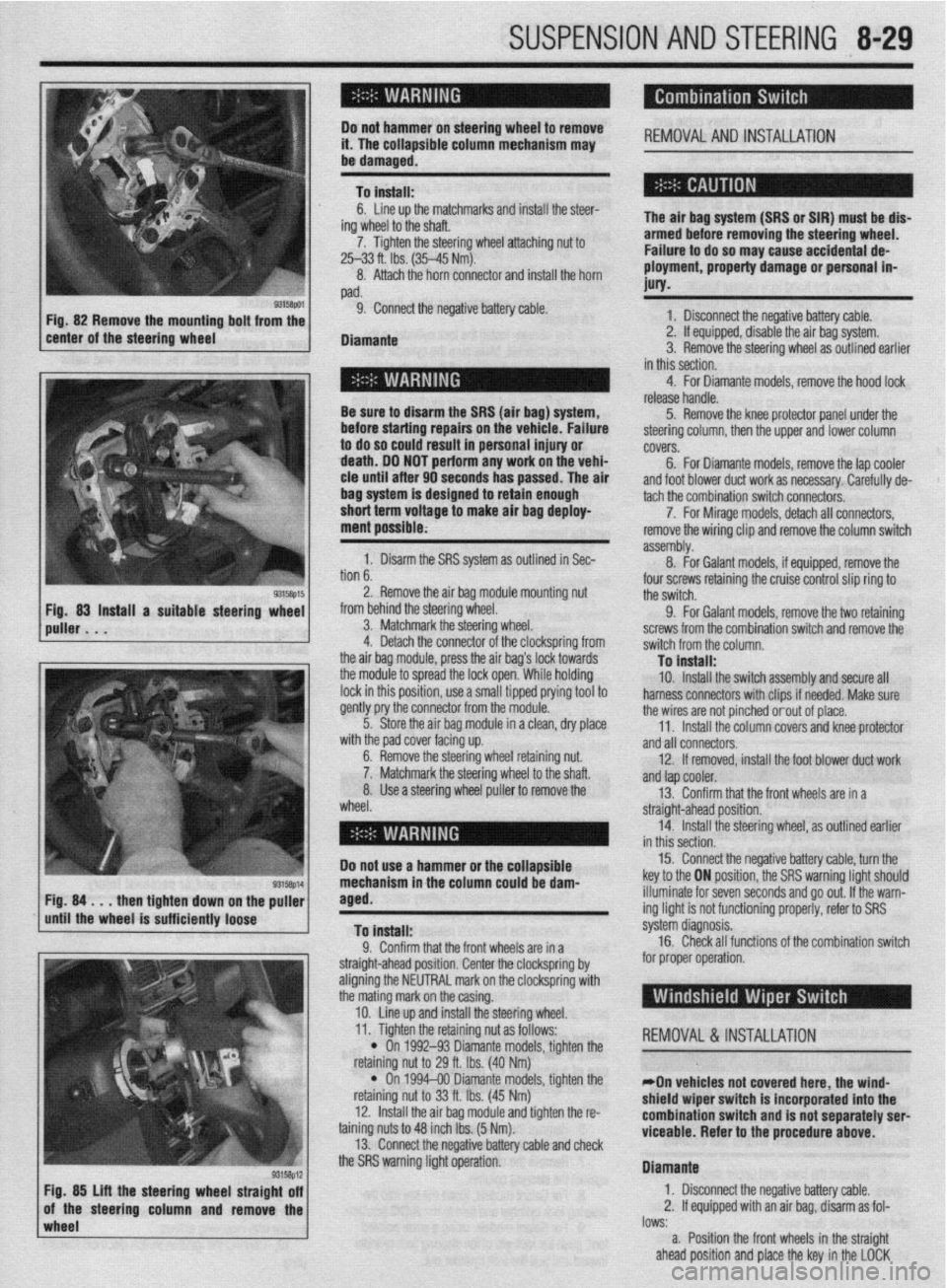
b. 1. Disarm the SRS system as outlined in Sec-
. . ^ I assembly. tach the combination switch connecto&.
8. -
7. For Mirage models, detach all connectors,
For Galant models, if equipped, remove the remove the wiring clip and remove the column switch
2. Remove the air bag module mounting nut
from behind the steering wheel.
3. Matchmark the steering wheel.
4. Detach the connector of the clockspring from
the air baq module, press the air baa’s lock towards four screws retaining the cruise control slip ring to
the switch.
9. For Galant models, remove the two retaining
screws from the combination switch and remove the
switch from the column.
Tn install: the modub to spread the lock open:While holding
lock in this position, use a small tipped prying tool to
gently pry the connector from the module.
5. Store the air bag module in a clean, dry place
..# ,I I I .
ut.
Iaft. wlrn me paa cover racmg up.
6. Remove the steering wheel retaining nl
7. Matchmark the steering wheel to the sl
8. Use a steering wheel puller to remove the
wheel. - . . - _-. . _
10. Install the switch assembly and secure all
harness connectors with clips if needed. Make sure
the wires are not pinched orout of place.
11. Install the column covers and knee protector
and all connectors.
12. If removed, install the foot blower duct work
anfl tan cnnler -..- .-
r --- ”
13. Confirm that the front wheels are in a
straight-ahead position.
14. Install the steering wheel, as outlined earlier
in thir
Do not use a hammer or the ~r”---‘~‘- 15. Connect the negative battery cable, turn the
key to the ON position, the SRS warning light should
NW down
rinntlv
wImpl* the puller
iem Fig. 84 . . . then tighte
until the wheel is suffL,,,,, lVvoV
To install:
0 Pnnfirm that thn frnnt whnalc ,?A in , .I. ““llllllll u,a, ,110 ll”lll I.ll~rJlJ CnIj 111 a
straight-ahead position. Center the clockspring by
aligning the NEUTRAL mark on the clockspring with
the mating mark on the casing.
10. Line up and install the steering wheel. illuminate for seven seconds and go out. If the warn-
ing light is not functioning properly, refer to SRS
s’ .’ ystem cllagnosls.
16. Check all functions of the combination switch
for proper operation.
wheel lows:
a. Position the front wheels in the straight
ahead position and place the key in the LOCK
93158p12 Fig. 85 Lift the steering wheel straight off
of the steering column and remove the 11. Tighten the retaining nut as follows:
REMOVAL &INSTALLATION
l On 1992-93 Diamante models, tighten the
nut to 29 ft. Ibs. (40 Nm) retammg I
l On
retaining I
12. lnstal
taining nuts 1
13. Conn
“... . ..” .‘“J...*.” ‘&.“WSJ Y..“.” . ..rn” VII”“..
the SRS warning light operation. 1994-00 Diamante models, tighten the
iut to 33 ft. Ibs. (45 Nm)
II the air bag module and tighten the r&
:o 48 inch Ibs. (5 Nm).
wt the rwnative hatim rahle ami rhwk
*On vehicles not covered here, the wind-
shield wiper switch is incorporated into the
combination switch and is not separately serl
viceable. Refer to the procedure
above.
Diamante
1. Disconnect the negative battery cable.
2. If equipped with an air bag, disarm as fol-
I” .L
Page 326 of 408
8-30 SUSPENSION AND STEERING
position. Remove the key from the ignition lock
cylinder.
b. Disconnect the negative battery cable and
insulate the cable end with high-quality electrical
tape or similar non-conductive wrapping.
c. Wait at least 1 minute before working on
the vehicle. The air bag system is designed to re-
tain enough voltage to deploy the air bag for a
short period of time even after the battery has
been disconnected.
3. Remove the steering wheel. as outlined ear-
lier in this section.
4. Remove the hood lock release handle.
5. Remove the switches from the knee protector
below the steering column, and remove the exposed
retaining screws. Then remove the knee protector.
6. Remove the column covers.
7. Remove necessary duct work and detach the
windshield wiper switch connectors. +
8. Remove the retaining screws and remove the
windshield wiper switch assembly from the steering
column.
To install: 9. Install the wiper switch to the steering col-
umn and connect the connectors.
IO. Install any removed duct work.
11. Install the column covers.
12. Install the knee protector and switches.
13. Install the hood release handle.
14. Confirm that the front wheels are in a straight
ahead position. Install the steering wheel, as outlined
earlier in this section.
15. Connect the negative battery cable and check
the windshield wiper and washer for proper opera-
tion
REMOVAL &INSTALLATION
The air bag system (SRS or SIR) must be dis-
armed before removing the steering wheel.
Failure to do so may cause accidental de-
ployment, property damage or personal in-
jury.
1. If equipped, properly disarm the air bag sys-
tern:
2. Disconnect the negative battery cable.
3. Remove the hood lock release lever from the
lower panel.
4. Remove the lower instrument panel knee pro-
tector.
5. Remove the ductwork with the lower knee
panel and remove the steering wheel assembly.
Use proper steering wheel puller equipment
when removing the steering wheel. The use
of a hammer for removal could damage the
collapsible mechanism within the column.
6. Remove the lower and upper steering column
covers.
7. For Diamante models, remove the lap cooler
and foot shower duct work.
8. If necessary, remove the clip that holds the
wiring harness against the steering column. 9. Detach all necessary connectors.
10. For Galant and Diamante models, remove the
retaining screws, then remove the entire column
switch/clockspring assembly from the left side of the
steering column.
11. For Diarnante models, remove the mounting
screws from the ignition switch and pull the switch
from the interlock cylinder.
12. Insert the key into the steering lock cylinder
and turn to the
ACC position.
13. With a small, pointed tool, push the lock pin
of the steering lock cylinder inward and pull the lock
cylinder out.
14. Remove the key reminder switch, if equipped.
To install: 15. For Mirage, install the lock cylinder in the
lock cylinder bracket. Make sure the cylinder oper-
ates properly before breaking off the heads of the
special bolts, if the bracket was replaced.
16. For Galant and Diarnante models, install the
lock cylinder into the interlock housing. Be sure the
lock pin snaps into place. Install the ignition switch
into the interlock housing. Align the keyway of the ig-
nition switch with the lock cylinder and secure with
the mounting screws.
17. For Galant and Diamante models, install the
column switch/clockspring assembly to the and con-
nect the harness.
18. install the key reminder switch, if equipped.
19. Attach the harness connections and install
the wiring clip.
20. If removed, install the lap cooler and foot
shower duct work.
21. Install the steering column upper and lower
covers.
22. If necessary, install the knee protector and the
steering wheel.
23. Install the hood lock release lever.
24. Connect the negative battery cable, enable the
air bag system, and check the ignition switch and
lock for proper operation.
REMOVALANDINSTALLATION
Mirage and Galant
I. Disconnect the negative battery cable. If
equipped, disarm the air bag system.
2. Remove the hood lock release lever from the
lower panel.
3. Remove the lower instrument panel knee pro-
tector.
4. Remove the ductwork with the lower knee
panel and remove the steering wheel assembly.
*Use proper steering wheel puller equip-
ment when removing the steering wheel. The
use of a hammer for removal could damage
the collapsible mechanism within the col-
umn.
5. Remove the lower steering column cover.
6. Remove the upper steering column cover.
7. Remove the clip that holds the wiring harness
against the steering column.
8. For Galant models, insert the key into the
steering lock cylinder and turn to the ACC position.
9. For Galant models, using a small pointed
tool, push the lock pin of the steering lock cylinder
inward and pull the lock cylinder out. IO. For Galant models, remove the key reminder
switch, if equipped.
11. Unplug the ignition switch harness connec-
tor. Remove the ignition switch mounting screws and
pull the switch from the steering lock cylinder.
*Vehicles equipped with automatic
transaxle have safety-lock systems and will
have a key interlock cable installed in a slide
lever on the side of the key cyfinder. Care-
fully unhook the interlock cable from the lock
cylinder while withdrawing the cylinder from
the lock housing.
To install:
*To remove the steerlng lock, use a hack-
saw or equivalent to cut the special bolts
through the bracket. The bracket and bolts
must be replaced with new ones.
12. With the ignition key removed, install the
slide lever and the interlock cable to the steering lock
cylinder. Apply grease to the interlock cable and in-
stall the cylinder into the lock housing. Check for
normal operation of the interlock system.
13. Install the ignition switch into the rear of the
lock cylinder housing. Be sure to align the keyway of
the ignition switch with interlock cylinder.
14. Attach the harness connections and install
the wiring clip.
15. Install the steering column upper and lower
covers.
16. Install the knee protector.
17. Connect the negative battery cable, enable the
air
bag system (if equipped) and check the ignition
switch and lock for proper operation.
Diamante
Work MUST NOT be started until at least 90
seconds after the ignition switch is turned to
the LOCK position and the negative battery
cable is disconnected from the battery. This
will allow time for the air bag system backup
power supply to deplete its stored energy
preventing accidental air bag deployment
which could result in unnecessary air bag
system repairs and/or personal injury.
I. Disconnect the negative battery cable.
2. Disarm the air bag system, as outlined in
Section 6.
3. Remove the steering wheel, as outlined ear-
lier in this section.
4. Remove the hood lock release handle.
5. Remove the switches from the knee protector
below the steering column and remove the exposed
retaining screws. Then remove the knee protector.
6. Remove the steering column upper and lower
covers. Use care removing the covers to prevent
breakage of alignment tabs.
7. Remove lap cooler and foot shower
duct work. Detach the ignition switch harness connectors.
8. Remove mounting screws from the ignition
switch and pull switch from interlock cylinder.
To install: 9. Install ignition switch into interlock housing.
Align keyway of ignition switch with lock cylinder and
secure with mounting screws.
IO. Connect the ignition switch electrical harness
Plug.
Page 327 of 408
I
SUSPENSION AND STEERING 8-31
11. Install lap cooler and foot shower duct work.
1.’ Disconnect the negative battery cable. 11.
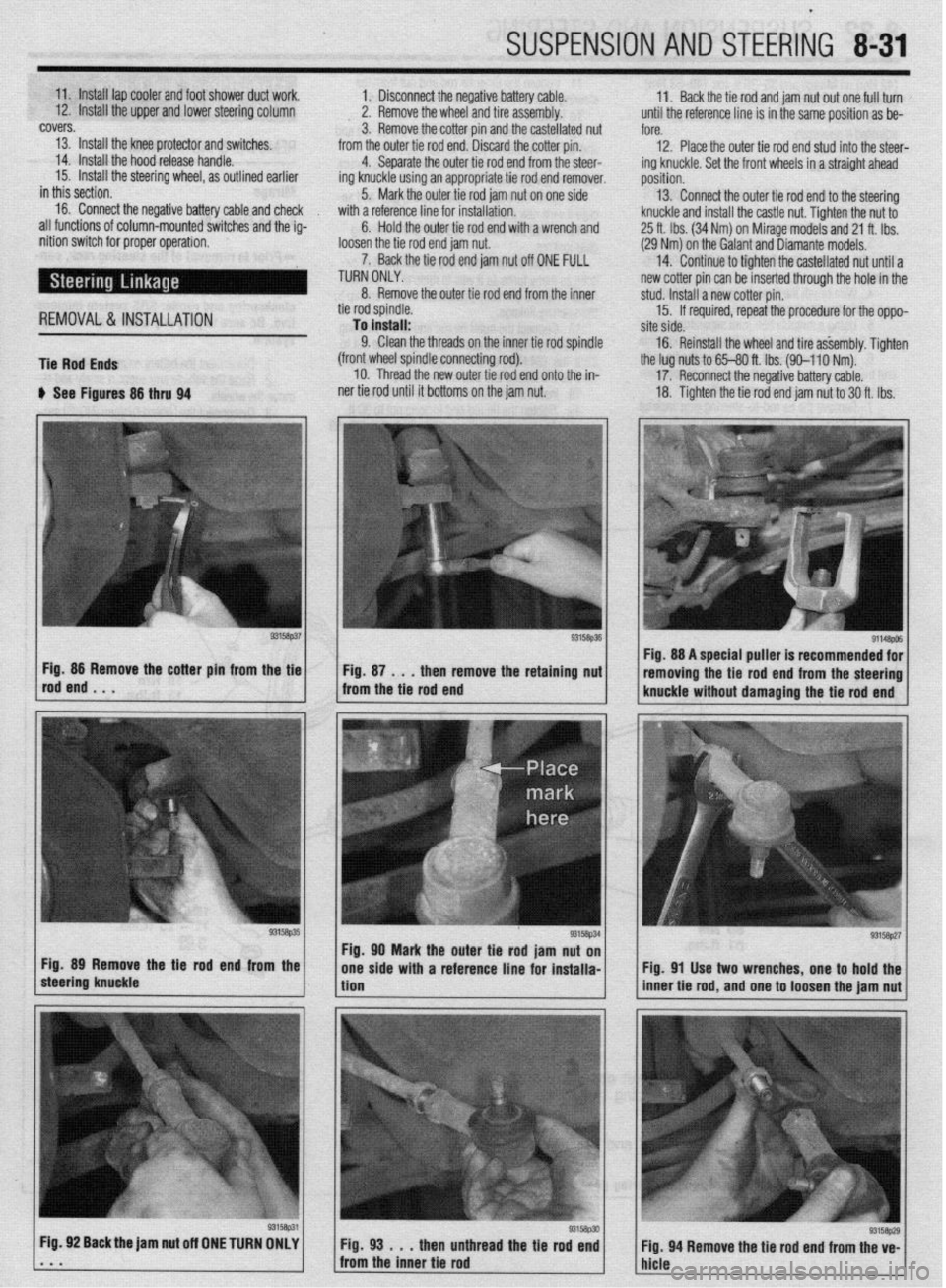
12. Install the upper and lower steering column Back the tie rod and jam nut out one full turn
2. Remove the wheel and tire assembly. until the reference line is in the same position as be-
covers.
3. Remove the cotter pin and the castellated nut
fore.
13. Install the knee protector and switches.
12. Place the outer tie rod end stud into the steer-
14. Install the hood release handle. from the outer tie rod end. Discard the cotter pin.
4. Separate the outer tie rod end from the steer-
15. Install the steering wheel, as outlined earlier
ing knuckle using an appropriate tie rod end remover. ing knuckle. Set the front wheels in a straight ahead
in this section. position.
16. Connect the negative battery cable and check 5. Mark the outer tie rod jam nut on one side 13. Connect the outer tie rod end to the steering
with a reference line for installation.
all functions of column-mounted switches and the ig-
Hold the outer tie rod end with a wrench and knuckle and install the castle nut. Tighten the nut to
6.
nition switch for proper operation,
loosen the tie rod end jam nut. 25 ft. Ibs. (34 Nm) on Mirage models and 21 ft. Ibs.
(29 Nm) on the Galant and Diamante models.
7. Back the tie rod end jam nut off ONE FULL
TURN ONLY. 14. Continue to tighten the castellated nut until a
new cotter pin can be inserted through the hole in the
8. Remove the outer tie rod end from the inner
REMOVAL&INSTALLATION
Tie Rod Ends tie rod spindle.
To install:
9. Clean the threads on the inner tie rod spindle
(front wheel spindle connecting rod).
10. Thread the new outer tie rod end onto the in- stud. Install a new cotter pin.
15. If required, repeat the procedure for the oppo-
site side,
16. Reinstall the wheel and tire a&embly. Tighten
the lug nuts to 65-80 ft. Ibs. (90-l 10 Nm).
u See Figures 86 thru 94 ner tie rod until it bottoms on the jam nut. 17. Reconnect the negative battery cable.
18. Tighten the tie rod end jam nut to 30 ft. Ibs.
g3’5a~51 Fig. 89 Remove the Be rod end from the
steering knuckle *
Fig. 92 Back the jam nut off ONE TURN OMLY
. * m Fig. 98 . . .
then unthread the tie rod end
Fig. 94 Remove the tie rod end from the ve-
from the inner tie rod
hicle Fig. 88 A special puller is recommended for
removing the tie rod end from the steering
knuckle without damaging the tie rod end
Fig. 91 Use two wrenches, one to hold the
inner tie rod, and one to loosen the jam nut
93158p29
Page 371 of 408
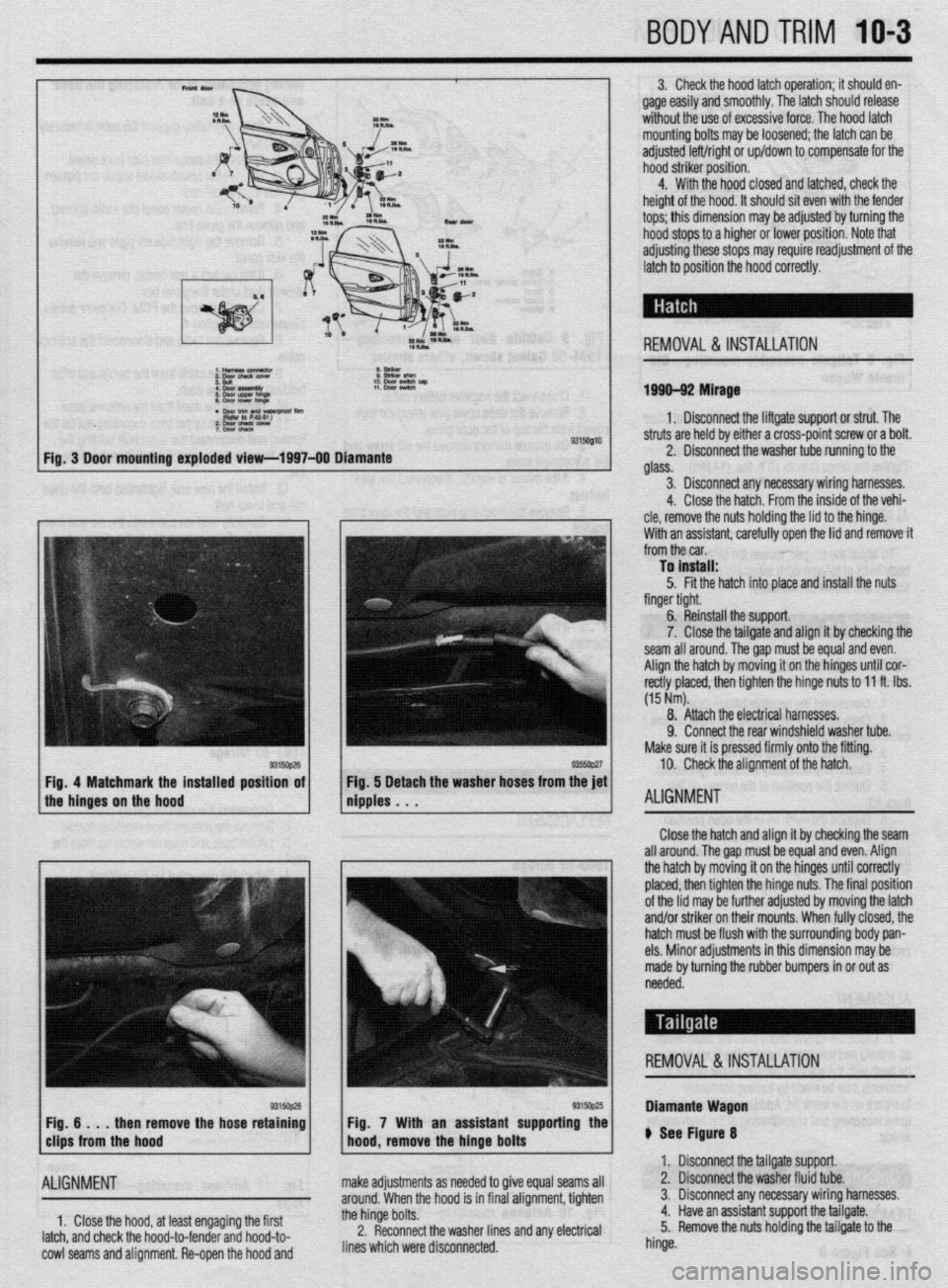
BODYANDTRIM 10-3
3. Check the hood latch operation; it should en-
gage easily and smoothly. The latch should release
without the use of excessive force. The hood latch
mounting bolts may be loosened; the latch can be
adjusted left/right or up/down to compensate for the
hood striker position.
4. With the hood closed and latched, check the
height of the hood. It should sit even with the fender
tops; this dimension may be adjusted by turning the
hood stops to a higher or lower position. Note that
adjusting these stops may require readjustment of the
latch to position the hood correctly.
REMOVAL &INSTALLATION
1999-92 Mirage
1. Disconnect the liftgate support or strut. The
9315Ql10 struts are held by either a cross-point screw or a bolt.
2. Disconnect the washer tube running to the
glass.
3. Disconnect any necessary wiring harnesses.
4. Close the hatch. From the inside of the vehi-
cle, remove the nuts holding the lid to the hinge.
With an assistant. carefullv ooen the lid and remove it
from the car. ’
To install:
5. Fit the hatch into place and install the nuts
finger tight.
6. Reinstall the support.
7. Close the tailgate and align it by checking the
seam all around. Thegap must be equal and even.
Align the hatch by moving it on the hinges until cor-
rectly placed, then tighten the hinge nuts to 11 ft. Ibs.
(15 Nm).
8. Attach the electrical harnesses.
9. Connect the rear windshield washer tube.
Make sure it is pressed firmly onto the fitting.
10. Check the alignment of the hatch.
ALIGNMENT
Close the hatch and align it by checking the seam
all around. The gap must be equal and even. Align
the hatch by moving it on the hinges until correctly
placed, then tighten the hinge nuts. The final position
of the lid may be further adjusted by moving the latch
and/or striker on their mounts. When fully closed, the
hatch must be flush with the surrounding body pan-
els. Minor adjustments in this dimension may be
made by turning the rubber bumpers in or out as
needed.
REMOVAL &INSTALLATION
then remove the hose retaining
ALIGNMENT
1, Close the hood, at least engaging the first
latch, and check the hood-to-fender and hood-to-
cowl seams and alignment. Re-open the hood and Fig. 7 With an assistant supporting the
make adjustments as needed to give equal seams all
around. When the hood is in final alignment, tighten
the hinge bolts.
2. Reconnect the washer lines and any electrical
lines which were disconnected. Diamante Wagon
ti See Figure 8
1. Disconnect the tailgate support.
2. Disconnect the washer fluid tube.
3. Disconnect any necessary wiring harnesses.
4. Have an assistant support the tailgate.
5. Remove the nuts holding the tailgate to the
hinge.
Page 375 of 408
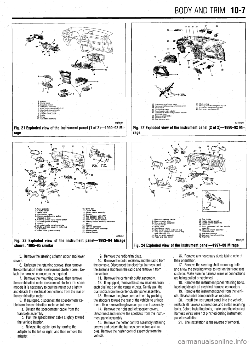
BODYANDTRIM IO-7
1. Ashtray
2 cenrer DaneI
3. Sunglass pocket
4 Side panel assembly
5 Knee protector assembly (L
6 Hood lock release handle
7 Column cover. lower
8 Column cover. upper
9 Radio
10 Striker
11. Glove box assembly
Fig. 21 Exploded view of the instrument panel (1 of 2)-1990-92 Mi-
rage
1. Knee pmtector
2. Column cover
3. Meter bezel
4. Combination meter
5. Remote control mirror switch.
rhsostat or plug
6. Coin box or rear wper washer switch
7. Aw outlet panel assembly
6. Ashtray
0. Air outlet center panel assembly
10. Radio and tape player or radio plug
11. Cup holder
12. Under COW (1993 models) 14. Comer panel
15. Heater control assembly %.
16. Speaker
17. Side defroster grille (RH)
16. Side defroster grille (LH)
19. Hood lock release handle
20. Ee$ng column assembly mstallation
21. Adapter
22 Harness oonnector
23. Instrument panel assembly
24. Ashtray panel
25. Ashtray bracket
9315og21 Fig. 23 Exploded view of the instrument panel-1993-94 Mirage
shown, 1995-95 similar
5. Remove the steering column upper and lower
covers.
6. Unfasten the retaining screws, then remove
the combination meter (instrument cluster) bezel. De-
tach the harness connectors as required.
7. Remove the mounting screws, then remove
the combination meter (instrument cluster). On some
models it is necessary to pull the meter out slightly
and detach the electrical connections from the rear of
the combination meter.
8. If equipped, disconnect the speedometer ca-
ble from the combination meter as follows:
a. Detach the speedometer cable from the
transaxle assembly.
b. Pull the speedometer cable slightly toward
the vehicle interior.
c. Release the cable lock by turning the
adapter to the left or right, and then remove the
adapter.
18
S-14Nm
7-lOh.lbs.
12 ln~v~rnent panel cover. lower
13 Hearer control assembly w,tallatlon screw
14 Meter bezel
15 Combination meter
16 Speedometer cable adapter
17 Comblnawn meterwr~ng harness connec-
. to1 co”“ectlo”s
16 Speaker amlsh (R H )
19 Speaker RHI e
20 S\de defroster grllla 21 Clock 01 plug
22 Steering shaft mount,ng bolt and nut
23 Ins!rument panel mounting bolts
24 Instrument panel assembly
9315og20 Fig. 22 Exploded view of the instrument panel (2 of 2)-1990-92 Mi-
rage
Fig. 24
1. Hood lock release handle
2. Knee protactor plug
3. Knee protector assembly
4 Column cover
5. Meter bezel
6. Combination meter
7. Door mrror control swich or plug
6. Auto-CNISO control mam swtch. fog
hght swtch M plug
0. Stde av outlet assembly
10 Radio and tape player 11. Cup holder
12. Heater control panel
13. Heater control assembly
14. Glove box
15 Front passenger’s 81, bag module
assembly
16. Steerq column assembly
lnstallatlon bon
17. Harness connector
16. Instrument panel assembly
19 Grommet
Exploded view of the instrument panel-l 997-00 Mirage
9. Remove the radio trim plate.
IO. Remove the radio retainers and the radio from
the console. Disconnect the electrical harness and
the antenna lead from the radio and remove it from
the vehicle.
11. Remove the center air outlet assembly.
12. If equipped, remove the screw retainers from
each dial knob on the center cluster. Gently pull the
dial knobs from the center cluster panel assembly.
13. Remove the glove compartment by pushing
the stoppers toward the rear of the vehicle to unlock
them, then remove the glove compartment assembly.
14. Remove the right and left speaker covers.
Disconnect and remove the speakers from the instru-
ment panel assembly.
15. Remove the heater control assembly retaining
screws and detach the harness connectors and ca-
bles. Remove the heater control assembly from the
vehicle. , 16. Remove any necessary ducts taking note of
their orientation,
17. Remove the steering shaft mounting bolts
and allow the steering wheel to rest on the front seat
cushion, Make sure no harness wires or connections
are being pulled or stretched.
18. Remove the instrument panel retaining bolts,
label and detach all electrical harness connectors.
19. Remove the instrument panel from the vehi-
cle. Disassemble components as required.
20. Install the instrument panel into the vehicle,
reattach all harness connections and install retaining
bolts. Before installing bolts, make sure the electrical
harness wires were not pinched during instrument
panel installation.
21. The installation is the reverse of removal.