fuel filter location MITSUBISHI DIAMANTE 1900 Repair Manual
[x] Cancel search | Manufacturer: MITSUBISHI, Model Year: 1900, Model line: DIAMANTE, Model: MITSUBISHI DIAMANTE 1900Pages: 408, PDF Size: 71.03 MB
Page 10 of 408

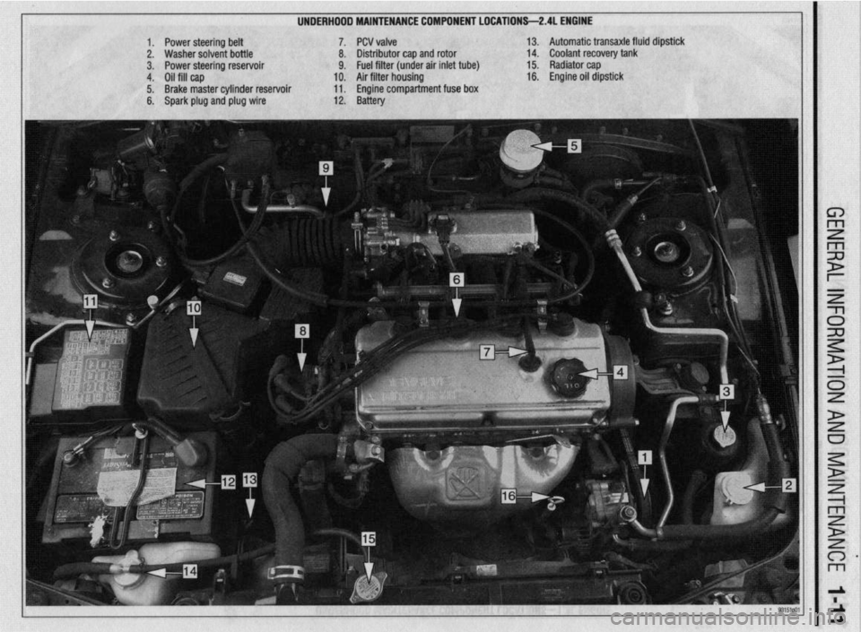
UNDERHDDD MAINTENANCE COMPONENT LOCATIONS-2AL ENGINE
II
1. Power steering belt 7. PCV valve
2. Washer solvent bottle 8. Distributor cap and rotor
3. Power steering reservoir 9. Fuel filter (under air inlet tube)
4. Oil fill cap 10. Air filter housing
5. Brake master cylinder reservoir 11. Engine compartment fuse box
6. Spark plug and plug wire 12. Battery 13. Automatic transaxle fluid dipstick
14. Coolant recovery tank
15. Radiator cap
16. Engine oil dipstick
Page 11 of 408

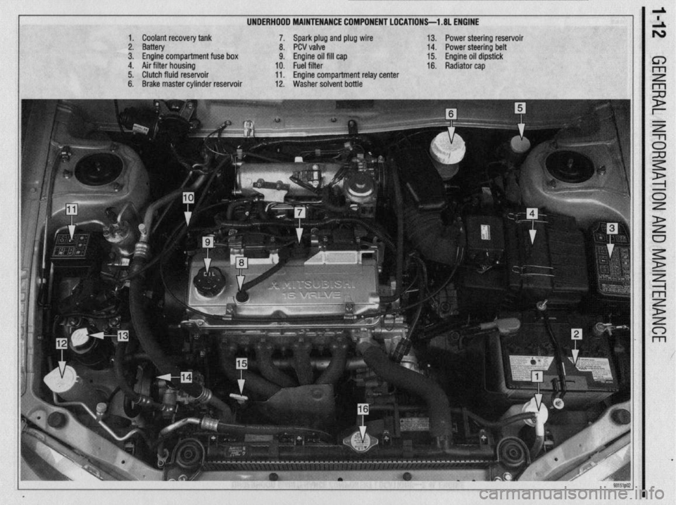
UNDERHOOD MAINTENANCE COMPONENT LOCATIONS-l .8L ENGINE
1. Coolant recovery tank
2. Battery
3. Engine compartment fuse box
4. Air filter housing
5. Clutch fluid reservoir
6. Brake master cylinder reservoir 7. Spark plug and plug wire
8. PCV valve
9. Engine oil fill cap
10. Fuel filter
11. Engine compartment relay center
12. Washer solvent bottle 13. Power steering reservoir
14. Power steering belt
15. Engine oil dipstick
16. Radiator cap
Page 87 of 408

3-26 ENGINEANDENGINEOVERHAUL
18. Remove the self-locking nuts and the small
retaining bolt holding the exhaust pipe to the bottom
of the exhaust manifold. Separate the pipe from the
manifold and remove the gasket.
19. Remove the bolts holding the support brace
to the bottom of the intake manifold.
20. Use the special hex wrench (MB 998051-01)
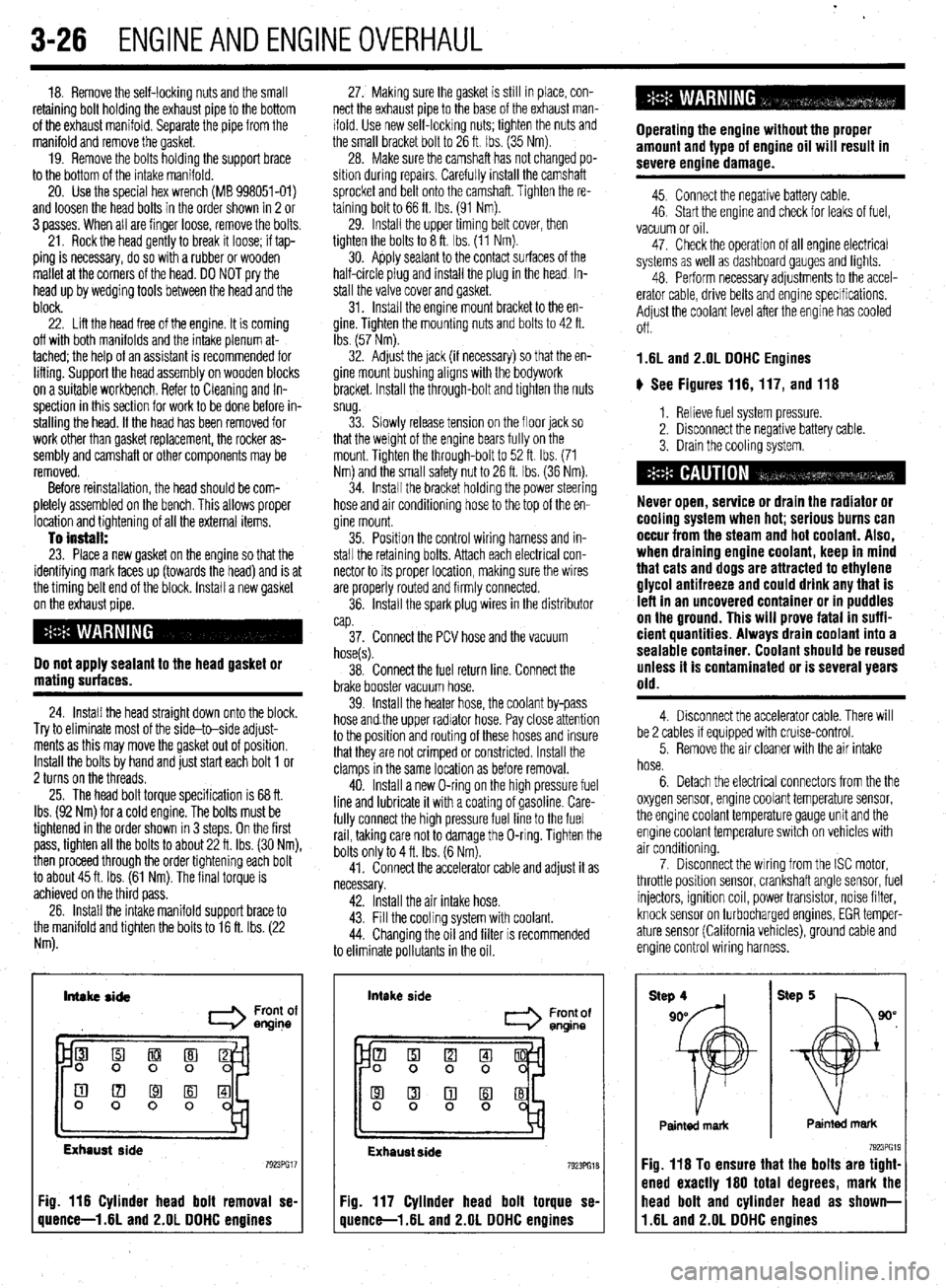
and loosen the head bolts in the order shown in 2 or
3 passes. When all are finger loose, remove the bolts.
21. Rock the head gently to break it loose; if tap-
ping is necessary, do so with a rubber or wooden
mallet at the corners of the head. DO NOT pry the
head up by wedging tools between the head and the
block.
22. Lift the head free of the engine. It is coming
off with both manifolds and the intake plenum at-
tached; the help of an assistant is recommended for
lifting. Support the head assembly on wooden blocks
on a suitable workbench. Refer to Cleaning and In-
spection in this section for work to be done before in-
stalling the head. If the head has been removed for
work other than gasket replacement, the rocker as-
sembly and camshaft or other components may be
removed.
Before reinstallation, the head should be com-
pletely assembled on the bench. This allows proper
location and tightening of all the external items.
To install: 23. Place a new gasket on the engine so that the
identifying mark faces up (towards the head) and is at
the timing belt end of the block. Install a new gasket
on the exhaust pipe.
Do not apply sealant to the head gasket or
mating surfaces.
24. Install the head straight down onto the block.
Try to eliminate most of the side-to-side adjust-
ments as this may move the gasket out of position.
Install the bolts by hand and just start each bolt 1 or
2 turns on the threads.
25. The head bolt torque specification is 68 ft.
Ibs. (92 Nm) for a cold engine. The bolts must be
tightened in the order shown in 3 steps. On the first
pass, tighten all the bolts to about 22 ft. Ibs. (30 Nm),
then proceed through the order tightening each bolt
to about 45 ft. Ibs. (61 Nm). The final torque is
achieved on the third pass.
26. Install the intake manifold support brace to
the manifold and tighten the bolts to 16 ft. Ibs. (22
Nm). 27. Making sure the gasket is still in place, con-
nect the exhaust pipe to the base of the exhaust man-
ifold. Use new self-locking nuts; tighten the nuts and
the small bracket bolt to 26 ft. Ibs. (35 Nm).
28. Make sure the camshaft has not changed po-
sition during repalrs. Carefully install the camshaft
sprocket and belt onto the camshaft. Tighten the re-
taining bolt to 66 ft. Ibs. (91 Nm).
29. Install the upper timing belt cover, then
tighten the bolts to 8 ft. Ibs. (11 Nm).
30. Apply sealant to the contact surfaces of the
half-circle plug and install the plug in the head In-
stall the valve cover and gasket.
31. Install the engine mount bracket to the en-
gine. Tighten the mounting nuts and bolts to 42 ft.
Ibs. (57 Nm).
32. Adjust the jack (if necessary) so that the en-
gine mount bushing aligns with the bodywork
bracket. Install the through-bolt and tighten the nuts
snug.
33. Slowly release tension on the floor jack so
that the weight of the engine bears fully on the
mount. Tighten the through-bolt to 52 ft. Ibs. (71
Nm) and the small safety nut to 26 ft. tbs. (36 Nm).
34. Install the bracket holding the power steering
hose and air conditioning hose to the top of the en-
gine mount.
35. Position the control wiring harness and in-
stall the retaining bolts. Attach each electrical con-
nector to its proper location, making sure the wires
are properly routed and firmly connected.
36. Install the spark plug wires in the distributor
cap.
37. Connect the PCV hose and the vacuum
hose(s).
38. Connect the fuel return line. Connect the
brake booster vacuum hose.
39. Install the heater hose, the coolant by-pass
hose and.the upper radiator hose. Pay close attention
to the position and routing of these hoses and insure
that they are not crimped or constricted. Install the
clamps in the same location as before removal.
40. Install a new O-ring on the high pressure fuel
line and lubricate it with a coating of gasoline. Care-
fully connect the high pressure fuel line to the fuel
rail, taking care not to damage the O-ring. Tighten the
bolts only to 4 ft. Ibs. (6 Nm).
41. Connect the accelerator cable and adjust it as
necessary.
42. Install the air intake hose.
43. Fill the cooling system with coolant.
44. Changing the oil and filter is recommended
to eliminate pollutants in the oil.
Intake side
I Front of
engine
Exhaust side
Fig. 116 Cylinder head bolt removal se-
quence-l .6L and 2.OL DDHC engines intake
side
Front of
entine
Exhaust side 7923PG18
Fig. 117 Cylinder head bolt torque se-
quence-l .6L and 2.OL DDHC engines Operating the engine without the proper
amount and type of engine oil will result in
severe engine damage.
45. Connect the negative battery cable.
46. Start the engine and check for leaks of fuel,
vacuum or oil.
47. Check the operation of all engine electrical
systems as well as dashboard gauges and lights.
48. Perform necessary adjustments to the accel-
erator cable, drive belts and engine specifications.
Adjust the coolant level after the engine has cooled
Off.
1.6L and 2.OL DDHC Engines
ti See Figures 116,117, and 116
1. Relieve fuel system pressure.
2. Disconnect the negative battery cable.
3. Drain the cooling system.
Never open, service or drain the radiator or
cooling system when hot; serious burns can
occur from the steam and hot coolant. Also,
when draining engine coolant, keep in mind
that cats and dogs are attracted to ethylene
glycol antifreeze and could drink any that is
left in an uncovered container or in puddles
on the ground. This will prove fatal in suffi-
cient quantities. Always drain coolant into a
sealable container. Coolant should be reused
unless it is contaminated or is several years
old.
4. Disconnect the accelerator cable. There will
be 2 cables if equipped with cruise-control.
5. Remove the air cleaner with the air intake
hose.
6. Detach the electrical connectors from the the
oxygen sensor, engine coolant temperature sensor,
the engine coolant temperature gauge unit and the
engine coolant temperature switch on vehicles with
air conditioning.
7. Disconnect the wiring from the ISC motor,
throttle position sensor, crankshaft angle sensor, fuel
injectors, ignition coil, power transistor, noise filter,
knock sensor on turbocharged engines, EGR temper-
ature sensor (California vehicles), ground cable and
engine control wiring harness.
Painted mark Painted mark
Fig. 116 To ensure that the bolts are tight-
ened exactly 160 total degrees, mark the
11.6L and 2.OL DDHC engines head bolt and cylinder head as shown-
Page 396 of 408

II-14 TROUBLESHOOTING
b. Check for low voltage at the bulb socket positive terminal or a poor ground. If voltage
is low, or the ground marginal, trace the wiring to, and check for loose, damaged or
corroded wires and electrical terminals; repair as necessary.
c. Check the light switch operation and replace if necessary.
1. Interior light inoperative
a. Verify the interior light switch location and position(s), and set the switch in the cor-
rect position.
b. Check for battery voltage and ground at the interior light bulb socket. If battery voltage
and ground are present, replace the bulb. If voltage is not present, check the interior
light fuse for battery voltage. If the fuse is missing, replace the fuse. If the fuse has
blown, or if battery voltage is present, refer to the wiring diagram to troubleshoot the
cause for an open or shorted circuit. If ground is not present, check the door switch
contacts and clean or repair as necessary.
2. Interior light works intermittent/y
a. Check the bulb for a damaged filament, and replace if damaged.
b. Check the bulb and bulb socket for corrosion, and clean or replace the bulb and
socket.
c. Check for loose, damaged or corroded wires and electrical terminals; repair as neces-
sary.
d. Check the door and light switch operation, and replace if necessary.
3. Interior light very dim
a. Check the bulb and bulb socket for corrosion, and clean or replace the bulb and
socket.
b. Check for low voltage at the bulb socket positive terminal or a poor ground. If voltage
is low, or the ground marginal, trace the wiring to, and check for loose, damaged or
corroded wires and electrical terminals; repair as necessary.
c. Check the door and light switch operation, and replace if necessary.
1. One brake light inoperative
a. PressPress the brake pedal and check for battery voltage and ground at the brake light
bulb socket. If present, replace the bulb. If either battery voltage or ground is not pre-
sent, refer to the wiring diagram to troubleshoot.
2. Both brake lights inoperative
a. Press the brake pedal and check for battery voltage and grou’nd at the brake light bulb
socket. If present, replace both bulbs. If battery voltage is not present, check the brake
light switch adjustment and adjust as necessary. If the brake light switch is properly
adjusted, and battery voltage or the ground is not present at the bulb sockets, or at the
bulb electrical connector with the brake pedal pressed, refer to the wiring diagram to
troubleshoot the cause of an open circuit.
3. One or both brake lights very dim
a. Press the brake pedal and measure the voltage at the brake light bulb socket. If the
measured voltage is close to the battery voltage, check for a poor ground caused by a
loose, damaged, or corroded wire, terminal, bulb or bulb socket. If the ground is
bolted to a painted surface, it may be necessary to remove the electrical connector and
clean the mounting surface, so the connector mounts on bare metal. If battery voltage
is low, check for a poor connection caused by either a faulty brake light switch, a
loose, damaged, or corroded wire, terminal or electrical connector. Refer to the wiring
diagram to troubleshoot the cause of a voltage drop.
1. Warning light(s) stay on when the engine is started
Ignition, Battery or Alternator Warning light a. Check the alternator output and voltage regulator operation, and replace as necessary.
b. Check the warning light wiring for a shorted wire.
Check Engine Light a. Check the engine for routine maintenance and tune-up status. Note the engine tune-up
specifications and verify the spark plug, air filter and engine oil condition; replace
and/or adjust items as necessary.
b. Check the fuel tank for low fuel level, causing an intermittent lean fuel mixtur
e. Top off fuel tank and reset check engine light.
c. Check for a failed or disconnected engine fuel or ignition component, sensor or con-
trol unit and repair or replace as necessary.
d. Check the intake manifold and vacuum hoses for air leaks and repair as
necessary.
e. Check the engine’s mechanical condition for excessive oil consumption.
Anti-Lock Braking System (ABS) Light a. Check the wheel sensors and sensor rings for debris, and clean as necessary.
b. Check the brake master cylinder for fluid leakage or seal failure and replace as neces-
sary.
c, Check the ABS control unit, pump and proportioning valves for proper operation; re-
place as necessary.
d. Check the sensor wiring at the wheel sensors and the ABS control unit for a loose or
shorted wire, and repair as necessary.
brake Warning Light a. Check the brake fluid level and check for possible leakage from the hydraulic lines and
seals. Top off brake fluid and repair leakage as necessary.
b. Check the brake linings for wear and replace as necessary.
c. Check for a loose or shot-ted brake warning light sensor or wire, and replace or repair
as necessary.
Oil Pressure Warning Light a. Stop the engine immediately. Check the engine oil level and oil filter condition, and
top off or change the oil as necessary.
b. Check the oil pressure sensor wire for being shorted to ground. Disconnect the wire
from the oil pressure sensor and with the ignition in the ON position, but not running,
the oil pressure light should not be working. If the light works with the wire discon-
nected, check the sensor wire for being shorted to ground. Check the wire routing to
make sure the wire is not pinched and check for insulation damage. Repair or replace
the wire as necessary and recheck before starting the engine.
c. Remove the oil pan and check for a clogged oil pick-up tube screen.
d. Check the oil pressure sensor operation by substituting a known good sensor.
e. Check the oil filter for internal restrictions or leaks, and replace as necessary.
WARNING: If the engine is operated with oil pressure below the manufac-
turer’s specification, severe (and costly) engine damage could occur. Low
oil pressure can be caused by excessive internal wear or damage to the en-
gine bearings, oil pressure relief valve, oil pump or oil pump drive mecha-
nism.
Before starting the engine, check for possible causes of rapid oil loss, such as leaking
oil lines or a loose, damaged, restricted, or leaking oil filter or oil pressure sensor. If the
engine oil level and condition are acceptable, measure the engine’s oil pressure using a
pressure gauge, or determine the cause for the oil pressure warning light to function
when the engine is running, before operating the engine for an extended period of time.
Another symptom of operating an engine with low oil pressure is the presence of severe
knocking and tapping noises.
Parking Brake Warning Light a. Check the brake release mechanism and verify the parking brake has been fully re-
leased.
b. CheckCheck the parking brake light switch for looseness or misalignment.
c. CheckCheck for a damaged switch or a loose or shorted brake light switch wire, and
replace or repair as necessary.
2. Warning light(s) flickers on and off when driving
Ignition, Battery or Alternator Warning Light a. Check the alternator output and voltage regulator operation. An intermittent condition
may indicate worn brushes, an internal short, or a defective voltage regulator. Replace
the alternator or failed component.
b. Check the warning light wiring for a shorted, pinched or damaged wire and repair as
necessary.
Check Engine Light a. Check the engine for required maintenance and tune-up status. Verify engine tune-up
specifications, as well as spark plug, air filter and engine oil condition; replace and/or
adjust items as necessary.
b. Check the fuel tank for low fuel level causing an intermittent lean fuel mixture. Top off
fuel tank and reset check engine light.
c. Check for an intermittent failure or partially disconnected engine fuel and ignition
component, sensor or control unit; repair or replace as necessary.
d. Check the intake manifold and vacuum hoses for air leaks, and repair as necessary.
e. Check the warning light wiring for a shorted, pinched or damaged wire and repair as
necessary.
Anti-Lock Braking System (ABS) Light a. Check the wheel sensors and sensor rings for debris, and clean as necessary.
b. Check the brake master cylinder for fluid leakage or seal failure and replace as neces-
sary.
c. Check the ABS control unit, pump and proportioning valves for proper operation, and
replace as necessary.