fuel filter MITSUBISHI DIAMANTE 1900 Repair Manual
[x] Cancel search | Manufacturer: MITSUBISHI, Model Year: 1900, Model line: DIAMANTE, Model: MITSUBISHI DIAMANTE 1900Pages: 408, PDF Size: 71.03 MB
Page 1 of 408
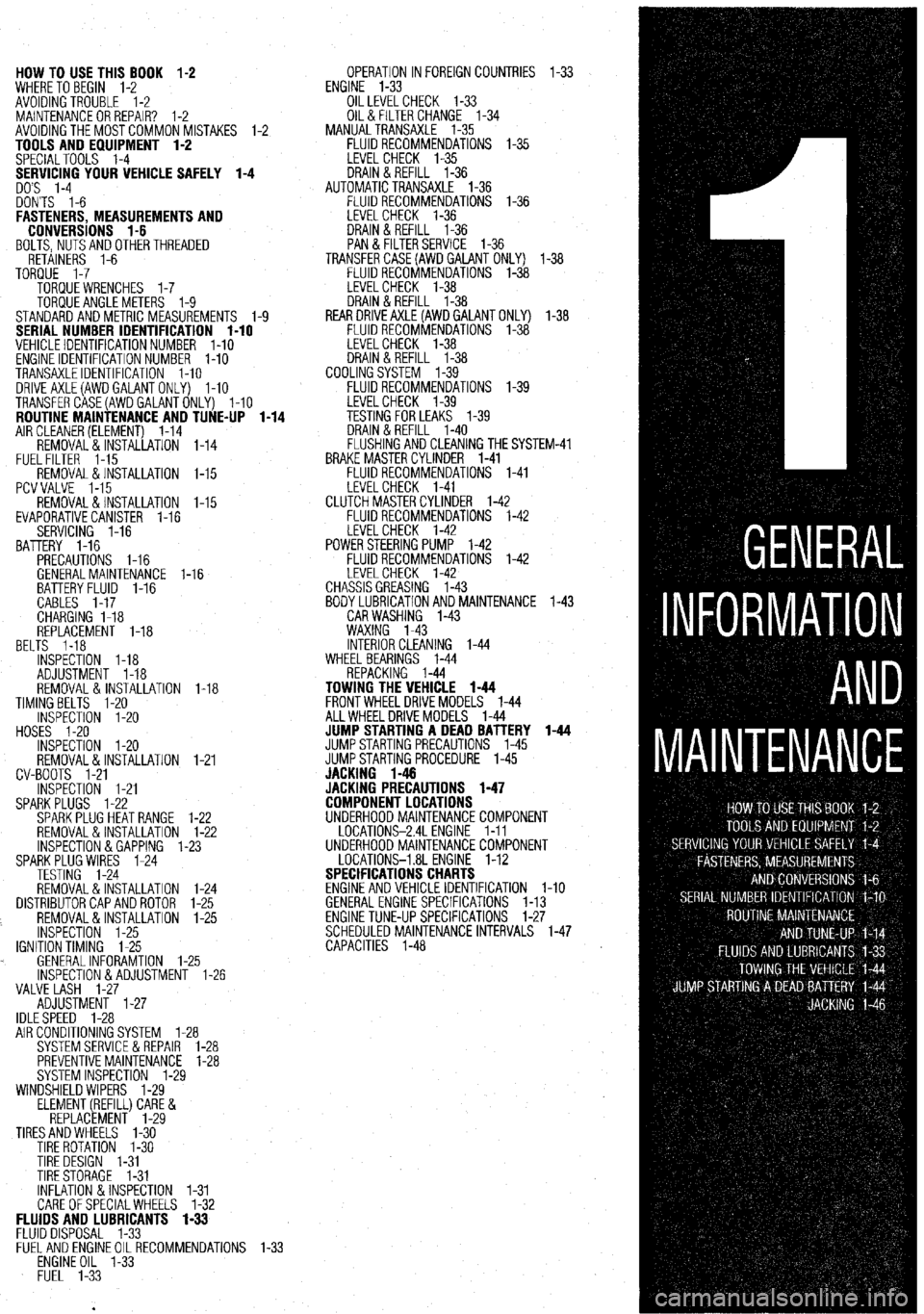
HOW TO USE THIS BOOK 1-2
WHERE TOBEGIN l-2
AVOIDINGTROUBLE 1-2
MAINTENANCEORREPAIR? 1-2
AVOIDINGTHEMOSTCOMMONMISTAKES l-2
TOOLS AND EQUIPMENT 1-2
SPECIALTOOLS l-4
YOUR VEHICLE SAFELY 1-4
DON'TS l-6
FASTENERS, MEASUREMENTS AND
CONVERSIONS l-6
BOLTS,NUTSANDOTHERTHREADED
RETAINERS 1-6
TORQUE l-7
TORQUEWRENCHES l-7
TORQUEANGLEMETERS 1-9
STANDARDANDMETRIC MEASUREMENTS l-9
SERIAL NUMBER IDENTIFICATION l-10
VEHICLE IDENTIFICATION NUMBER l-10
ENGINE IDENTIFICATION NUMBER I-10
TRANSAXLEIDENTIFICATION I-10
DRlVEAXLE(AWDGALANTONLY) l-10
TRANSFERCASE(AWDGALANTONLY) l-10
ROUTINE MAINTENANCE AND TUNE-UP l-14
AIRCLEANER(ELEMENT) 1-14
REMOVAL&INSTALLATION 1-14
FUELFILTER 1-15
REMOVAL &INSTALLATION l-15
PCVVALVE l-15
REMOVAL&INSTALLATION l-15
EVAPORATIVECANISTER l-16
SERVICING 1-16
BATTERY 1-16
PRECAUTIONS I-16
GENERALMAINTENANCE 1-16
BEL BATTERYFLUID 1-16
CABLES I-17
CHARGING I-18
REPLACEMENT 1-18
TS 1-18
INSPECTiON l-18
ADJUSTMENT 1-18
REMOVAL&INSTALLATION 1-18
TIMINGBELTS l-20
INSPECTION l-20
HOSES I-20
INSPECTION l-20
REMOVAL&INSTALLATION
CV-BOOTS 1-21
INSPECTION l-21
SPARKPLUGS l-22
SPARKPLUGHEATRANGE
REMOVAL&INSTALLATION
INSPECTION &GAPPING 1.
SPARKPLUG WIRES 1-24
TESTING 1-24
REMOVAL&INSTALLATION
DISTRIBUTORCAPANDROTOR
REMOVAL&INSTALLATION
INSPECTION 1-25
IGNITIONTIMING 1-25
. GENERALINFORAMTION l-
lNSPECTlON&ADJUSTMENl
VALVE LASH l-27
ADJUSTMENT l-27
IDLESPEED 1-28 1-21
l-22
l-22
-23
1-24
l-25
l-25
.25
1-26
AIR CONDITIONING SYSTEM 1-28
SYSTEMSERVlCEiiREPAlR l-28
PREVENTIVEMAINTENANCE 1-28
SYSTEM INSPECTION l-29
WINDSHIELD WIPERS l-29
ELEMENT(REFILL)CARE&
REPLACEMENT l-29
TIRESANDWHEELS l-30
TIRE ROTATION I-30
TIRE DESIGN 1-31
TIRESTORAGE l-31
INFLATION &INSPECTION l-31
CARE OFSPECIALWHEELS l-32 OPERATION INFOREIGNCOUNTRIES l-33
ENGINE l-33
OILLEVELCHECK 1-33
OIL& FILTER CHANGE l-34
MANUALTRANSAXLE l-35
FLUIDRECOMMENDATIONS l-35
LEVELCHECK l-35
DRAIN&REFILL l-36
AUTOMATICTRANSAXLE l-36
FLUIDRECOMMENDATIONS l-36
LEVELCHECK 1-36
DRAIN&REFILL l-36
PAN & FILTERSERVICE 1-36
TRANSFERCASE(AWDGAlANT ONLY) l-38
FLUIDRECOMMENDATIONS l-38
LEVELCHECK l-38
DRAIN&REFILL l-38
REARDRlVEAXLE(AWDGALANTONLY) l-38
FLUIDRECOMMENDATIONS l-38
LEVELCHECK l-38
DRAIN&REFILL l-38
COOLINGSYSTEM l-39
FLUIDRECOMMENDATIONS l-39
iM-41
FLUIDS AND LUBRICANTS 1-33
FLUID DISPOSAL 1-33
FlJELANDENGlNEOILRECOMMENDATlONS
ENGINE OIL l-33
FUEL l-33
Page 10 of 408
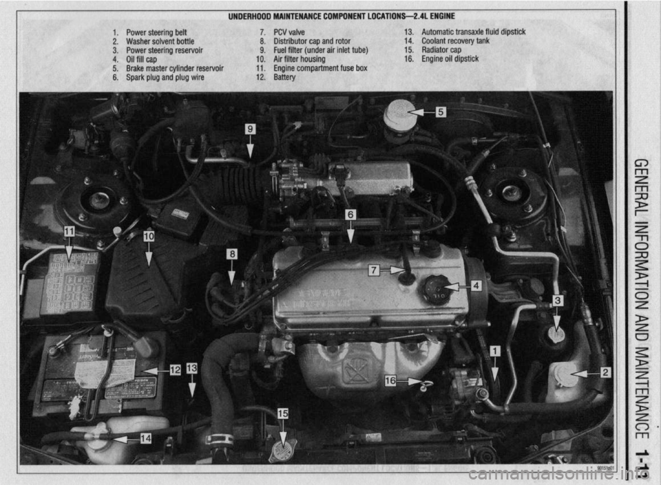
UNDERHDDD MAINTENANCE COMPONENT LOCATIONS-2AL ENGINE
II
1. Power steering belt 7. PCV valve
2. Washer solvent bottle 8. Distributor cap and rotor
3. Power steering reservoir 9. Fuel filter (under air inlet tube)
4. Oil fill cap 10. Air filter housing
5. Brake master cylinder reservoir 11. Engine compartment fuse box
6. Spark plug and plug wire 12. Battery 13. Automatic transaxle fluid dipstick
14. Coolant recovery tank
15. Radiator cap
16. Engine oil dipstick
Page 11 of 408
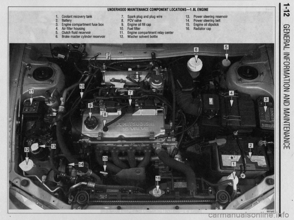
UNDERHOOD MAINTENANCE COMPONENT LOCATIONS-l .8L ENGINE
1. Coolant recovery tank
2. Battery
3. Engine compartment fuse box
4. Air filter housing
5. Clutch fluid reservoir
6. Brake master cylinder reservoir 7. Spark plug and plug wire
8. PCV valve
9. Engine oil fill cap
10. Fuel filter
11. Engine compartment relay center
12. Washer solvent bottle 13. Power steering reservoir
14. Power steering belt
15. Engine oil dipstick
16. Radiator cap
Page 14 of 408
GENERALINFORMATIONAND MAINTENANCE l-15
10. install the air cleaner assembly and the re- *Wrap shop towels around the fitting that is
tainer bolts. being dtsconnected to absorb residual fuel in
11. Connect the air intake hose. the lines. 9. While holding the fuel filter nut with aback-
up wrench, tighten the banjo bolt to 22 ft. Ibs. (30
Nm). Tighten the flare nut to 25 ft. Ibs. (35 Nm), with
12. Attach the solenoid valve.
4. Cover the hose connection with shop towels to a back-up wrench on the nut.
13. Connect the boost hose.
14. Attach the air flow sensor connector. prevent any splash of fuel that could be caused by 10. Tighten the filter mounting bolts to 10 ft. Ibs.
residual pressure in the fuel pipe line. Hold the fuel (14 Nm).
15. Connect the negative battery cable. 11.
filter nut securely with a backup wrench, then remove Connect the negative battery cable. Turn the
REMOVAL &INSTALLATION the banjo bolt on the engine feed line. Disconnect the
high-pressure fuel line from the filter. Remove and
discard the gaskets.
5. While holding the fuel filter nut securely with a
back-up wrench, loosen the filter feed pipe flare nut key to the ON position to pressurize the fuel system
and check for leaks.
12. If repairs of a leak are required, remember to
release the fuel pressure before opening the fuel sys-
tern.
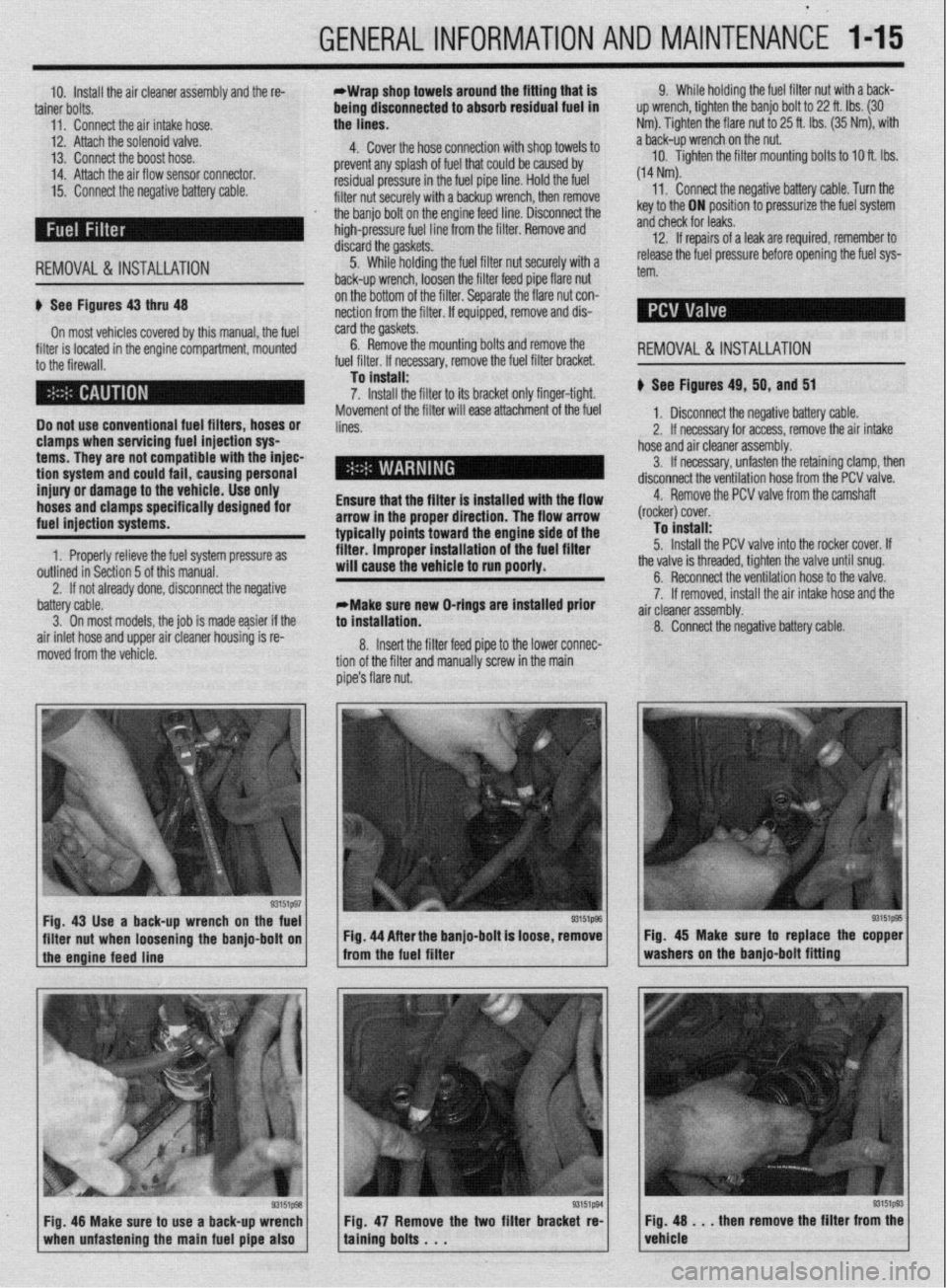
u See Figures 43 thru 48
On most vehicles covered by this manual, the fuel
filter is located in the engine compartment, mounted
to the firewall.
Do not use conventional fuel filters, hoses or
clamps when servicing fuel injection sys
terns. They are not compatible with the injec-
tion
system and could fail, causing personal
injury or damage to the vehicle. Use only
hoses and clamps specifically designed for
fuel injection systems.
1. Properly relieve the fuel system pressure as
outlined in Section 5 of this manual. on the bottom of the filter. Separate the flare nut con-
nection from the filter. If equipped, remove and dis-
card the gaskets.
6. Remove the mounting bolts and remove
. ,,,. ,.
.a r I,.,< I the
ruer rrrter. II necessary, remove me ruer rrrrer oracket.
To install:
7. Install the filter to its bracket only finger-tight.
Movement of the filter will ease attachment of the fuel
lines.
Ensure that the filter is installed with the flow
arrow in the proper direction. The flow arrow
typically points toward the engine side of the
filter. improper installation of the fuel filter
will cause the vehicle to run poorly.
2. If not already done, disconnect the negative REMOVAL&INSTALLATION
u See Figures 49, 50, and 51
1, Disconnect the negative battery cable.
2. If necessary for access, remove the air intake
hose and air cleaner assembly.
3. If necessary, unfasten the retaining clamp, then
disconnect the ventilation hose from the PCV valve.
4. Remove the PCV valve from the camshaft
(rocker) cover.
To install:
5. Install the PCV valve into the rocker cover. If
the valve is threaded, tighten the valve until snug.
battery cable.
3. On most models. the iob is made easier if the
air inlet hose and upper air cleaner housing is re-
moved from the vehicle. *Make sure new O-rings are installed prior
to installation.
8. Insert the filter feed pipe to the lower connec-
tion of the filter and manually screw in the main
pipe’s flare nut. 6. Reconnect the ventilation hose to the valve.
7. If removed, install the air intake hose and the
a .ir cleaner assembly.
8. Connect the negative battery cable.
Fig. 43 Use a back-up wrench on the fuel
I I
93151@3
filter nut when loosening the banjo-bolt on Fig. 44 After the banjo-bolt is loose, remove
I
1 the engine feed line - from the fuel filter
93151p93 Fig. 48 Make sure to use a back-up wrench
1 when unfastening the main fuel pipe also 1 Fig. 47 Remove the two filter bracket re-
taining bolts . . . Fig. 45 Make sure to replace the copper
washers on the banjo-bolt fitting
Fig. 48 . . . then remove the filter from the
vehicle
Page 32 of 408
GENERALINFORMATIONAND MAINTENANC-E 1133
Used fluids such as engine oil, transaxle fluid, an-
tifreeze and brake fluid are hazardous wastes and
must be disposed of properly. Before draining any
fluids, consult with your local authorities; in many ar-
eas, waste oil, antifreeze, etc. is being accepted as a
part of recycling programs. A number of service sta-
tions and auto parts stores are also accepting waste
fluids for recycling.
Be sure of the recycling center’s policies before
draining any fluids, as many will not accept different
fluids that have been mixed together.
ENGINE OIL
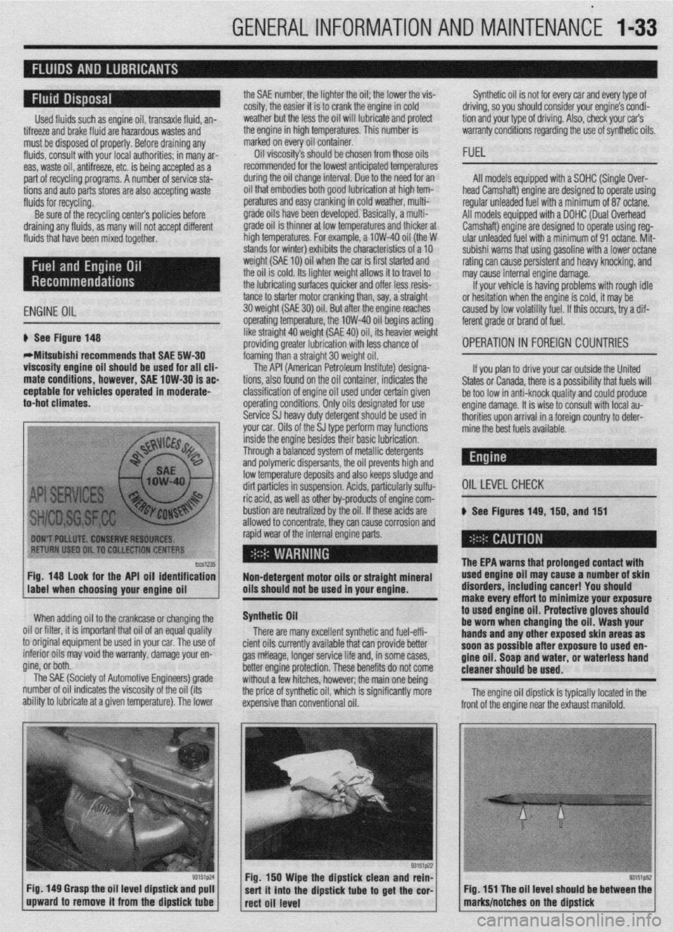
6 See Figure 148
WMitsubishi recommends that SAE 5W-30
viscosity engine oil should be used for all clia
mate conditions, however, SAE low-30 is ac
ceptable for vehicles operated in moderate-
to-hot climates. the SAE number, the lighter the oil; the lower the vis-
cosity, the easier it is to crank the engine in cold
weather but the less the oil will lubricate and protect
the engine in high temperatures. This number is
marked on every oil container.
Oil viscosity’s should be chosen from those oils
recommended for the lowest anticipated temperatures
during the oil change interval. Due to the need for an
oil that embodies both good lubrication at high tem-
peratures and easy cranking in cold weather, multi-
grade oils have been developed. Basically, a multi-
grade oil is thinner at low temperatures and thicker at
high temperatures. For example, a low-40 oil (the W
stands for winter) exhibits the characteristics of a 10
weight (SAE 10) oil when the car is first started and
the oil is cold. Its lighter weight allows it to travel to
the lubricating surfaces quicker and offer less resis-
tance to starter motor cranking than, say, a straight
30 weight (SAE 30) oil. But atier the ensine reaches
operating temperature, the low-40 oil begins acting
like straight 40 weight (SAE 40) oil, its heavier weight
providing greater lubrication with less chance of
foaming than a straight 30 weight oil. Synthetic oil is not for every car and every type of
driving, so you should consider your engine’s condi-
tion and your type of driving. Also, check your car’s
warranty conditions regarding the use of synthetic oils.
FUEL
All models equipped with a SOHC (Single Over-
head Camshaft) engine are designed to operate using
regular unleaded fuel with a minimum of 87 octane.
All models equipped with a DOHC (Dual Overhead
Camshaft) engine are designed to operate using reg-
ular unleaded fuel with a minimum of 91 octane. Mit-
subishi warns that using gasoline with a lower octane
rating can cause persistent and heavy knocking, and
may cause internal engine damage.
If your vehicle is having problems with rough idle
or hesitation when the enoine is cold, it mav be
caused by low volatility fuel. If this occurs, iry a dif-
ferent grade or brand of fuel.
'OPERATION 1~ FOREIGN COUNTRIES
lccS1235 Fig. 148 look for the API oil identification
Non-detergent motor oils or straight mineral
label when choosing your enaine oil oils should not be used in your engine.
When adding oil to the crankcase or changing the
0 Nil or filter, it is important that oil of an equal quality
I original equipment be used in your car. The use of
. tc mtenor 011s may void the warranty, damage your en-
gine, or both. __
The SAE (Society of Automotive Engineers) grade
number of oil indicates the viscosity of the oil (its
ability to lubricate at a given temperature). The lower
Fig. 149 Grasp the oil level dipstick and pull
upward to remove it from the dipstick
tube
The API (American Petroleum Institute) designa-
tions, also found on the oil container, indicates the
classification of engine oil used under certain given
operating conditions. Only oils designated for use
Service SJ heavy duty detergent should be used in
your car. Oils of the SJ type perform may functions If you plan to drive your car outside the United
States or Canada, there is a possibility that fuels will
be too low in anti-knock quality and could produce
engine damage. It is wise to consult with local au-
thorities upon arrival in a foreign country to deter-
mine the best fuels available.
inside the engine besides their basic lubrication.
Through a balanced system of metallic detergents
and polymeric dispersants, the oil prevents high and
low temperature deposits and also keeps sludge and
dirt particles in suspension. Acids, particularly sulfu-
OILLEVELCHECK ric acid, as well as other by-products of engine com-
bustion are neutralized by the oil. If these acids are
# See Figures 149, 150, and 151
allowed to concentrate, thev can cause corrosion and
rapid wear of the internal engine parts.
Synthetic Oil
There are many excellent synthetic and fuel-effi-
cient oils currently available that can provide better
gas mileage, longer service life and, in some cases,
better engine protection. These benefits do not come
without a few hitches, however; the main one being
the price of synthetic oil, which is significantly more
expensive than conventional oil.
.
The EPA warns that urolonoed contact with used engine oil ma; cause-a number of skin
disorders, including cancer! You should
make every effort to minimize your exposure
to
used engine oil. Protective gloves should
be worn when changing the oil. Wash your
hands and any other exposed skin areas as
soon as possible after exposure to used en-
gine oil. Soap and water, or waterless hand
cleaner should be used.
Fig. 150 Wipe the dipstick clean and rein-
sert it into the dipstick
tube to get the cor-
rect oil level The engine oil dipstick is typically located in the
Fig. 151 The oil level should be between the
marks/notches on the dipstick
Page 33 of 408
.
l-34 GENERALINFORMATIONAND MAINTENANCE
Engine oil level should be checked every time you
put fuel in the vehicle or are under the hood perform- miles of highway driving. Fluid which is warmed to
normal operating temperature will flow faster, drain
ing other maintenance.
1. Park the vehicle on a level surface.
2. The enaine mav be either hot or cold when
, if it is hot, wait a few min- checking oil level. The EPA warns that prolonged contact with
used engine oil may cause a num’ * * *
dianrAnrr inrldinn ranrnrl V#lll more completely and remove more contaminants
frnm tho clnnine
utes after the engine has been turned OFF to allow the
oil to drain back into the crankcase. If the engine is
cold, do not start it before checking the oil level. point on the oil pan. If not, you may have to raise the
vehicle slightly higher on one jackstand (side) than
3. Open the hood and locate the engine oil dip-
stick. Pull the dipstick from its tube, wipe it clean,
and reinsert it. Make sure the diDstick is fullv in-
serted.
4. Pull the dipstick from its tube again. Holding it to used engin
be worn whet
handsandan
so*m ..#a . . . . .
IDer 01 SKlll u,yu,u=,+, ,,,u,uu,,,u uu,,u=, i , vu should
uff art to minimize your exposure
le oil. Protective gloves should
1 changing the oil. Wash your
y other exposed skin areas as
111 aJ vv4ble after exposure to used en-
m nil St-mn mwl w&or nr umtarlncr hand gin Y “II. ““up “ll” .,U.“I, “rn W.Y.“. .““I .I....” cleaner should be used.
horizontally, read the oil level. The oilshould be be-
tween the MIN and MAX marks or the notches on the
dipstick. If the oil is below the MIN mark or lower
notch, add oil of the proper viscosity through the
capped opening of the valve cover. *The engine oil and oil filter should be
changed at the recommended intervals on
the Maintenance Chart. Though some manu-
facturers have at times recommended chang-
ing the filter only at every other oil change, ’
Chilton recommends that you always change
ll”,,, Cl>” ““y”‘“. 1. Raise and support the vehicle safely on jack-
stands. Make sure the oil drain olua is at the lowest
the other.
2. Before you crawl under the vehicle, take a look
at where you will be working and gather all the nec-
essary tools, such as a few wrenches or a ratchet and
strip of sockets, the drain pan, some clean rags and,
if the oil filter is more accessible from underneath the
vehicle, you will also want to grab a bottle of oil, the
new filter and a filter wrench at this time.
5. Reolace the diostick. and check the level aaain
. The benefit of fresh oil
p See Figures 152 thru 153
The oil and filter should be changed every 7,500
miles (12,000 km) under normal service and every
3,000 miles (5,000 km) under severe service.
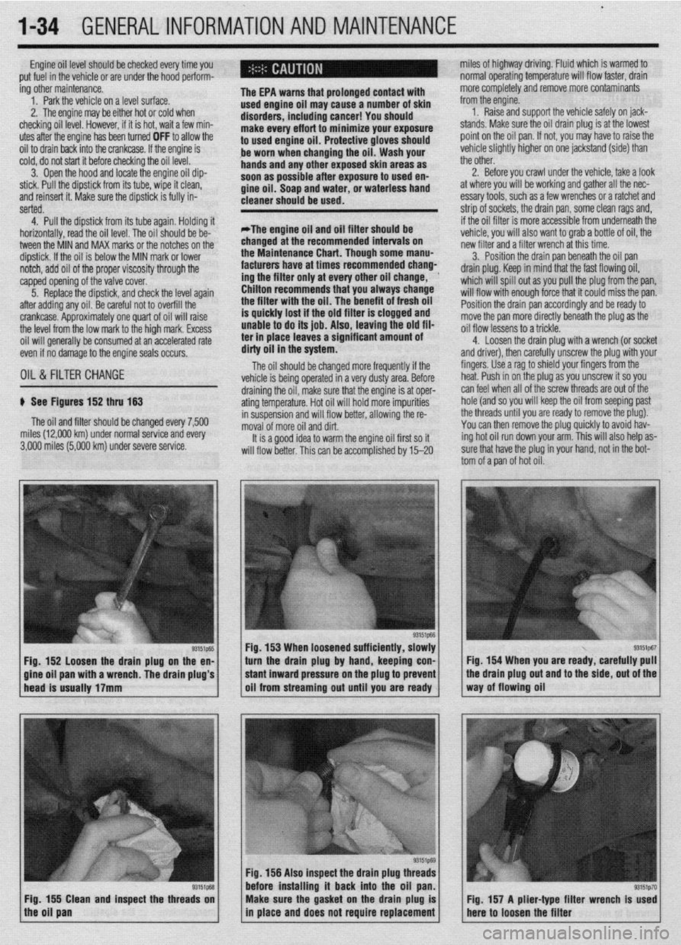
93151p-55 Fig. 152 loosen the drain plug on the en-
a wrench. The drain plug’s 3. Position the drain pan beneath the oil pan
drain plug. Keep in mind that the fast flowing oil,
which will spill out as you pull the plug from the pan,
will flow with enough force that it could miss the pan.
Position the drain pan accordingly and be ready to
move the pan more directly beneath the plug as the
oil flow lessens to a trickle.
4. Loosen the drain ~lua with a wrench (or socket
and driver), then carefuliy unscrew the plug with your
fingers. Use a rag to shield your fingers from the
heat. Push in on the plug as you unscrew it so you
draining the oil, make sure that the engine is at oper- can feel when all of the screw threads are out of the
ating temperature. Hot oil will hold more impurities hole (and so you will keep the oil from seeping past
in suspension and will flow better, allowing the re- the threads until you are ready to remove the plug).
moval of more oil and dirt. You can then remove the plug quickly to avoid hav-
It is a good idea to warm the engine oil first so it ing hot oil run down your arm. This will also help as-
will flow better. This can be accomolished bv 15-20 sure that have the plug in your hand, not in the bot-
tom of a pan of hot oil.
Fig. 153 When loosened sufficiently, slowly
turn the drain plug by hand, keeping con- Fig. 154 When you are ready, carefully pull
Fig. 156 Also inspect the drain plug th
before installing it back into the oil
Fig. 155 Clean and inspect the threads on
the oil pan Make sure the gasket on the drain plug is
in place and does not require replacement Fig. 157 A plier-type filter wrench Is used
here to loosen the filter
Page 46 of 408
GENERAL INFORMATION AND MAINTENANCE 1-47
ramps are also a handy and safe way to both raise l When the drive wheels are to remain on the
and support the vehicle. Be careful though, some ground, leave the vehicle in gear to help prevent it
ramps may be too steep to drive your vehicle onto
The following safety points cannot be overempha- from rolling.
without scraping the front bottom panels. Never sup-
sized:
l Always use jackstands to support the vehicle
port the vehicle on any suspension member (unless l Always block the opposite wheel or wheels to when you are working underneath. Place the stands
specifically instructed to do so by a repair manual) or
keep the vehicle from rolling off the jack. beneath the vehrcle’s jacking brackets Before climb-
by an underbody panel.
l When raising the front of the vehicle, firmly ap- ing underneath, rock the vehicle a bit to make sure it
ply the parking brake. is firmly supported.
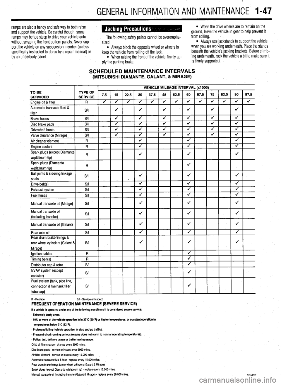
SCHEDULED MAINTENANCE INTERVALS (MITSUBISHI DIAMANTE, GALANT, & MIRAGE)
VEHICLE MILEAGE INTERVAL (x1000)
7.5 15
22.5 30 37.5 45 52.5 60 67.5 75 62.5 90 97.5
J J
J 4 J J 4 4 4 J J
J 4
4
J J J J 4 TO BE
Ball loints &steering linkage
S/I J J J
seals
Dnve belt(s) S/I 4 4 J
Fvha,,rt cvctom $/I
J J J LmI,..“w. “,YL”,‘. Fuel hoses
+
Manual transaxle oil (Galant)
connectlon & fuel tank filler
R. Replace S/I - Sefwce or Inspect FREQUENT OPERATION MAINTENANCE (SEVERE SERVICE) II a vehicle is operated under any of the following conditions it is considered severe service:
- Extremely dusty areas.
- 50% or more of the vehicle operation is in 32% (WF) or higher temperatures, or constant opsralion in
temperatures below 0% (32°F).
- Prolonged idling (vehicle operation in stop and go traffic).
_ Frequent short running periods (engine does not warm to normal operating temfwatures).
- Police, taxi, delivery usage or trailer towing usage.
0118 011 filter change-change every 3CQO miles.
Disc brake pads - sewce or Inspect ever 6COO miles
AN hlter element _ setwe or inspect every 15,000 miles.
Automatic transaxle lluld 8 filter . replace every 15,COO m&s.
Rear drum brake Ikmngs & rear wheel cylinders (Galant & Mirage)
Spark plugs (except Dlamante wlplabnum tip) - replace every 15,COO miles.
Manual transaxle 011 (mcludlng transfer (Galant & Mirage). replace every 30,000 miles.
Page 87 of 408
3-26 ENGINEANDENGINEOVERHAUL
18. Remove the self-locking nuts and the small
retaining bolt holding the exhaust pipe to the bottom
of the exhaust manifold. Separate the pipe from the
manifold and remove the gasket.
19. Remove the bolts holding the support brace
to the bottom of the intake manifold.
20. Use the special hex wrench (MB 998051-01)
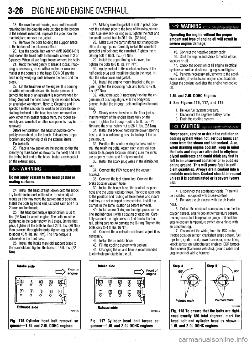
and loosen the head bolts in the order shown in 2 or
3 passes. When all are finger loose, remove the bolts.
21. Rock the head gently to break it loose; if tap-
ping is necessary, do so with a rubber or wooden
mallet at the corners of the head. DO NOT pry the
head up by wedging tools between the head and the
block.
22. Lift the head free of the engine. It is coming
off with both manifolds and the intake plenum at-
tached; the help of an assistant is recommended for
lifting. Support the head assembly on wooden blocks
on a suitable workbench. Refer to Cleaning and In-
spection in this section for work to be done before in-
stalling the head. If the head has been removed for
work other than gasket replacement, the rocker as-
sembly and camshaft or other components may be
removed.
Before reinstallation, the head should be com-
pletely assembled on the bench. This allows proper
location and tightening of all the external items.
To install: 23. Place a new gasket on the engine so that the
identifying mark faces up (towards the head) and is at
the timing belt end of the block. Install a new gasket
on the exhaust pipe.
Do not apply sealant to the head gasket or
mating surfaces.
24. Install the head straight down onto the block.
Try to eliminate most of the side-to-side adjust-
ments as this may move the gasket out of position.
Install the bolts by hand and just start each bolt 1 or
2 turns on the threads.
25. The head bolt torque specification is 68 ft.
Ibs. (92 Nm) for a cold engine. The bolts must be
tightened in the order shown in 3 steps. On the first
pass, tighten all the bolts to about 22 ft. Ibs. (30 Nm),
then proceed through the order tightening each bolt
to about 45 ft. Ibs. (61 Nm). The final torque is
achieved on the third pass.
26. Install the intake manifold support brace to
the manifold and tighten the bolts to 16 ft. Ibs. (22
Nm). 27. Making sure the gasket is still in place, con-
nect the exhaust pipe to the base of the exhaust man-
ifold. Use new self-locking nuts; tighten the nuts and
the small bracket bolt to 26 ft. Ibs. (35 Nm).
28. Make sure the camshaft has not changed po-
sition during repalrs. Carefully install the camshaft
sprocket and belt onto the camshaft. Tighten the re-
taining bolt to 66 ft. Ibs. (91 Nm).
29. Install the upper timing belt cover, then
tighten the bolts to 8 ft. Ibs. (11 Nm).
30. Apply sealant to the contact surfaces of the
half-circle plug and install the plug in the head In-
stall the valve cover and gasket.
31. Install the engine mount bracket to the en-
gine. Tighten the mounting nuts and bolts to 42 ft.
Ibs. (57 Nm).
32. Adjust the jack (if necessary) so that the en-
gine mount bushing aligns with the bodywork
bracket. Install the through-bolt and tighten the nuts
snug.
33. Slowly release tension on the floor jack so
that the weight of the engine bears fully on the
mount. Tighten the through-bolt to 52 ft. Ibs. (71
Nm) and the small safety nut to 26 ft. tbs. (36 Nm).
34. Install the bracket holding the power steering
hose and air conditioning hose to the top of the en-
gine mount.
35. Position the control wiring harness and in-
stall the retaining bolts. Attach each electrical con-
nector to its proper location, making sure the wires
are properly routed and firmly connected.
36. Install the spark plug wires in the distributor
cap.
37. Connect the PCV hose and the vacuum
hose(s).
38. Connect the fuel return line. Connect the
brake booster vacuum hose.
39. Install the heater hose, the coolant by-pass
hose and.the upper radiator hose. Pay close attention
to the position and routing of these hoses and insure
that they are not crimped or constricted. Install the
clamps in the same location as before removal.
40. Install a new O-ring on the high pressure fuel
line and lubricate it with a coating of gasoline. Care-
fully connect the high pressure fuel line to the fuel
rail, taking care not to damage the O-ring. Tighten the
bolts only to 4 ft. Ibs. (6 Nm).
41. Connect the accelerator cable and adjust it as
necessary.
42. Install the air intake hose.
43. Fill the cooling system with coolant.
44. Changing the oil and filter is recommended
to eliminate pollutants in the oil.
Intake side
I Front of
engine
Exhaust side
Fig. 116 Cylinder head bolt removal se-
quence-l .6L and 2.OL DDHC engines intake
side
Front of
entine
Exhaust side 7923PG18
Fig. 117 Cylinder head bolt torque se-
quence-l .6L and 2.OL DDHC engines Operating the engine without the proper
amount and type of engine oil will result in
severe engine damage.
45. Connect the negative battery cable.
46. Start the engine and check for leaks of fuel,
vacuum or oil.
47. Check the operation of all engine electrical
systems as well as dashboard gauges and lights.
48. Perform necessary adjustments to the accel-
erator cable, drive belts and engine specifications.
Adjust the coolant level after the engine has cooled
Off.
1.6L and 2.OL DDHC Engines
ti See Figures 116,117, and 116
1. Relieve fuel system pressure.
2. Disconnect the negative battery cable.
3. Drain the cooling system.
Never open, service or drain the radiator or
cooling system when hot; serious burns can
occur from the steam and hot coolant. Also,
when draining engine coolant, keep in mind
that cats and dogs are attracted to ethylene
glycol antifreeze and could drink any that is
left in an uncovered container or in puddles
on the ground. This will prove fatal in suffi-
cient quantities. Always drain coolant into a
sealable container. Coolant should be reused
unless it is contaminated or is several years
old.
4. Disconnect the accelerator cable. There will
be 2 cables if equipped with cruise-control.
5. Remove the air cleaner with the air intake
hose.
6. Detach the electrical connectors from the the
oxygen sensor, engine coolant temperature sensor,
the engine coolant temperature gauge unit and the
engine coolant temperature switch on vehicles with
air conditioning.
7. Disconnect the wiring from the ISC motor,
throttle position sensor, crankshaft angle sensor, fuel
injectors, ignition coil, power transistor, noise filter,
knock sensor on turbocharged engines, EGR temper-
ature sensor (California vehicles), ground cable and
engine control wiring harness.
Painted mark Painted mark
Fig. 116 To ensure that the bolts are tight-
ened exactly 160 total degrees, mark the
11.6L and 2.OL DDHC engines head bolt and cylinder head as shown-
Page 88 of 408
ENGlNEANDENGlNEOVERHALiL 3-27
8. Remove the upper radiator hose and the
sages thoroughly. Check the head for flatness. End to 31. Install the air cleaner and intake hose. Con-
overflow tube. end, the head should be within 0.002 in. (0.05mm) nect the breather hose.
9. Remove the spark plug cable center cover,
normally, with 0.008 in. (0.2mm) the maximum al- 32. Change the engine oil and oil filter,
then remove the spark plug cables.
lowed out of true. The total thickness allowed to be 33. Fill the system with coolant.
10. Disconnect and plug the high pressure fuel
removed from the head and block is 0.008 in.
line. 34. Connect the negative battery cable.
(0.2mm) maximum. 35. Run the vehicle until the thermostat opens,
11. Disconnect the small vacuum hoses.
23. Place a new head gasket on the cylinder and fill the radiator completely.
12. Remove the heater hose and water bypass
block with the identification marks at the front top 36. Check and adjust the idle speed and ignition
hose.
(upward) position. Make sure the gasket has the timing.
13. Remove the PCV hose.
proper identification mark for the engine. Do not use 37. Once the vehicle has cooled, recheck the
14. If turbocharged, remove the vacuum hoses,
sealer on the gasket. Replace the turbo gasket and coolant level.
water line and eyebolt connection for the oil line for
ring, if equipped.
the turbo.
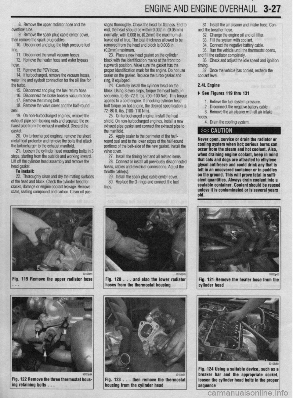
24. Carefully install the cylinder head on the 2.41 Engine
15. Disconnect and plug the fuel return hose. block. Using 3 even steps, torque the head bolts, in
16. Disconnect the brake booster vacuum hose.
sequence, to 65-72 ft. Ibs. (90-100 Nm). This torque b See Figures 119 thru 131
17. Remove the timing belt. applies to a cold engine. If checking cylinder head
18. Remove the valve cover and the half-round
bolt torque on hot engine, the desired specification is 1. Relieve the fuel system pressure.
seal.
7240 ft. Ibs. (100-110 Nm). 2. Disconnect the negative battery cable.
19. On non-turbocharged engines, remove the 3. Remove the air cleaner with all air intake
25. On turbocharged engine, install the heat
hoses.
exhaust pipe self-locking nuts and separate the ex-
shield. On non-turbocharged engines, install a new
haust pipe from the exhaust manifold. Discard the
exhaust pipe gasket and connect the exhaust pipe to 4. Drain the cooling system.
gasket.
the manifold.
20. On turbocharged engines, remove the sheet
26. Apply sealer to the perimeter of the half-
metal heat protector and remove the bolts that attach
round seal and to the lower edges of the half-round Never open, service or drain the radiator or
the turbocharger to the exhaust manifold.
portions of the belt-side of the new gasket. Install the cooling system when hot; serious burns can
21. Loosen the cylinder head mounting bolts in 3
valve cover. occur from the steam and hot coolant. Also,
steps, starting from the outside and working inward,
27. Install the timing belt and all related items. when draining engine coolant, keep in mind
Lift off the cylinder head assembly and remove the
28. Connect or install all previously disconnected that cats and dogs are attracted to ethylene
n head gasket.
hoses, cables and electrical connections. Adjust the glycol antifreeze and could drink any that is
To install:
throttle cable(s). left in an uncovered container or in puddles
22. Thoroughly clean and dry the mating surfaces
29. Install the spark plug cable center cover. on the ground. This will prove fatal in suffi-
of the head and block. Check the cylinder head for
30. Replace the O-rings and connect the fuel eient quantities. Always drain coolant into a
cracks, damage or engine coolant leakage. Remove
lines. sealable container. Coolant should be reused
scale, sealing compound and carbon. Clean oil pas- unless it is contaminated or is several years
old.
g3153p44 Fig. 119 Remove the upper radiator hose
* . . 1 Fig. 129 . . . and also the lower rad:gzi / cyl.der head g3153W
Fig 121 Remove the heater hose from the
hoses from the thermostat housing
Fig. 122 Remove the three thermostat hous-
Fig. 123 . . . then remove the thermostat
ing retaining bolts . . .
housing from the cylinder head
93153p50 Fig. 124 Using a suitable device, such as a
breaker bar and the appropriate socket,
loosen the cylinder head bolts in the proper
sequence
Page 90 of 408
ENGINEANDENGINEOVERHAUL 3-29
l HOzS sensor l ECT gauge sender l ECT sensor l MAP sensor l IAT sensor l TP sensor l IAC motor l injector harness l ignition coil l CMP sensor l EGR solenoid valve
33. Install the spark plug wires and cover,
34. Replace the O-rings and connect the fuel
lines.
35. Install the air cleaner and intake hose. Con-
nect the breather hose.
36. Fill the cooling system.
37. Connect the negative battery cable
3.01 DDHC Engine
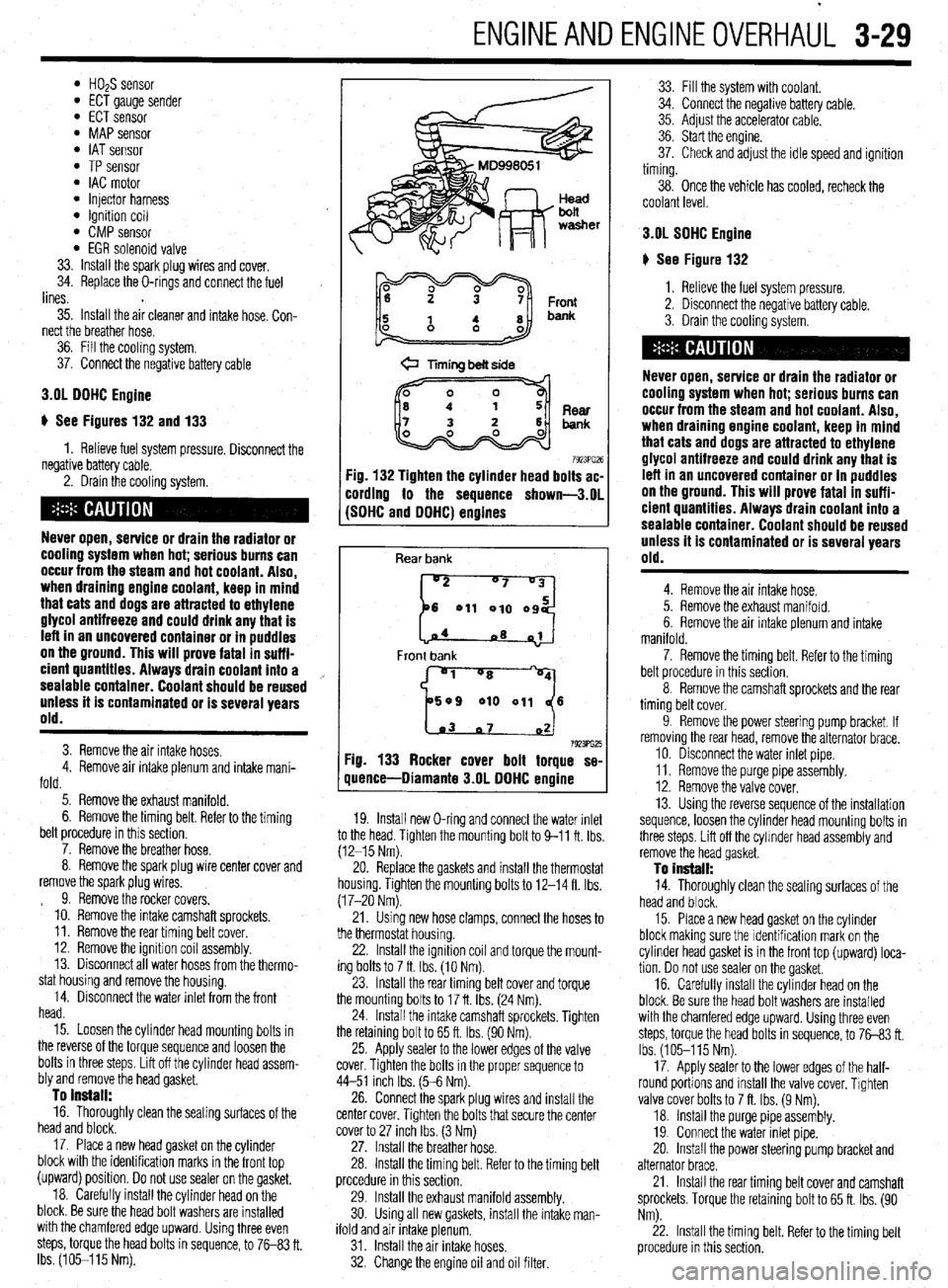
ti See Figures 132 and 133
1. Relieve fuel system pressure. Disconnect the
negative battery cable.
2. Drain the cooling system.
Never open, service or drain the radiator or
cooling system when hot; serious burns can
occur from the steam and hot coolant. Also,
when draining engine coolant, keep in mind
that cats and dogs are attracted to ethylene
glycol antifreeze and could drink any that is
left in an uncovered container or in puddles
on the ground. This will prove fatal in suffi-
cient quantltles. Always drain coolant into a
sealable container. Coolant should be reused
unless it is contaminated or is several years
old.
3. Remove the air intake hoses.
4. Remove air intake plenum and intake mani-
fold.
5. Remove the exhaust manifold.
6. Remove the timing belt. Refer to the timing
belt procedure in this section.
7. Remove the breather hose.
8. Remove the spark plug wire center cover and
remove the spark plug wires.
9. Remove the rocker covers.
10. Remove the intake camshaft sprockets.
11. Remove the rear timing belt cover.
12. Remove the ignition coil assembly.
13. Disconnect all water hoses from the thermo-
stat housing and remove the housing.
14. Disconnect the water inlet from the front
head.
15. Loosen the cylinder head mounting bolts in
the reverse of the torque sequence and loosen the
bolts in three steps. Lift off the cylinder head assem-
bly and remove the head gasket.
To install: 16. Thoroughly clean the sealing surfaces of the
head and block.
17. Place a new head gasket on the cylinder
block with the identification marks in the front top
(upward) position. Do not use sealer on the gasket,
18. Carefully install the cylinder head on the
block. Be sure the head bolt washers are installed
with the chamfered edge upward. Using three even
steps, torque the head bolts in sequence, to 76-83 ft.
Ibs. (105-115 Nm).
@ Timing belt side
7923PG26 :ig. 132 Tighten the cylinder head bolts ac-
:ording to the sequence shown-3.01
SDHC and DDHC) engines
Rear bank
[::od
04
~8 01
Front bank
'1 "8
509 010 011 6
1.03 07 02 7923ffi25 Fig. 133 Rocker cover bolt torque se-
quence-Diamante 3.OL DDHC engine
19. Install new O-ring and connect the water inlet
to the head. Tighten the mounting bolt to 9-11 ft. Ibs
(12-15 Nm).
20. Replace the gaskets and install the thermostat
housing. Tighten the mounting bolts to 12-14 ft. Ibs.
(17-20 Nm).
21. Using new hose clamps, connect the hoses to
the thermostat housing.
22. Install the Ignition coil and torque the mount-
ing bolts to 7 ft. Ibs. (10 Nm).
23. Install the rear timing belt cover and torque
the mounting bolts to 17 ft. Ibs. (24 Nm).
24. Install the intake camshaft sprockets. Tighten
the retaining bolt to 65 ft. Ibs. (90 Nm).
25. Apply sealer to the lower edges of the valve
cover. Tighten the bolts in the proper sequence to
44-51 inch Ibs. (5-6 Nm).
26. Connect the spark plug wires and install the
center cover. Tighten the bolts that secure the center
cover to 27 inch Ibs. (3 Nm)
27. Install the breather hose.
28. Install the timing belt. Refer to the timing belt
procedure in this section,
29. Install the exhaust manifold assembly.
30. Using all new gaskets, install the intake man-
ifold and air intake plenum.
31. Install the air intake hoses.
32. Change the engine oil and oil filter. 33. Fill the system wrth coolant.
34. Connect the negabve battery cable.
35. Adjust the accelerator cable.
36. Start the engine.
37. Check and adjust the idle speed and ignition
timing.
38. Once the vehicle has cooled, recheck the
coolant level.
3.OL SDHC Engine
# See Figure 132
1. Relieve the fuel system pressure.
2. Disconnect the negative battery cable.
3. Drain the cooling system.
Never open, service or drain the radiator or
cooling system when hot; serious burns can
occur from the steam and hot coolant. Also,
when draining engine coolant, keep in mind
that cats and dogs are attracted to ethylene
alvcol antifreeze and could drink any that is
Left in an uncovered container or in puddles
on the ground. This will Drove fatal in suff i-
cient quantities. Always drain coolant into a
sealable container. Coolant should be reused
Unless it is Contaminated or is several years
old.
4. Remove the air intake hose.
5. Remove the exhaust manifold.
6. Remove the air intake plenum and intake
manifold.
7. Remove the timing belt. Refer to the timing
belt procedure in this section.
8. Remove the camshaft sprockets and the rear
timing belt cover.
9. Remove the power steering pump bracket. If
removing the rear head, remove the alternator brace.
10. Disconnect the water inlet pipe.
11. Remove the purge pipe assembly.
12. Remove the valve cover,
13. Using the reverse sequence of the installation
sequence, loosen the cylinder head mounting bolts in
three steps. Lift off the cylmder head assembly and
remove the head gasket.
To install: 14. Thoroughly clean the sealing surfaces of the
head and block.
15. Place a new head gasket on the cylinder
block making sure the identification mark on the
cylrnder head gasket is in the front top (upward) loca-
tion. Do not use sealer on the gasket,
16. Carefully install the cylinder head on the
block. Be sure the head bolt washers are installed
with the chamfered edge upward. Using three even
steps, torque the head bolts in sequence, to 7683 ft.
Ibs. (105-115 Nm).
17. Apply sealer to the lower edges of the half-
round portions and install the valve cover. Tighten
valve cover bolts to 7 ft. Ibs. (9 Nm).
18. Install the purge pipe assembly.
19. Connect the water inlet pipe.
20. Install the power steering pump bracket and
alternator brace.
21. Install the rear timing belt cover and camshaft
sprockets. Torque the retaining bolt to 65 ft. Ibs. (90
Nm).
22. Install the timing belt. Refer to the timing belt
procedure in this section.