maintenance reset MITSUBISHI DIAMANTE 1900 Repair Manual
[x] Cancel search | Manufacturer: MITSUBISHI, Model Year: 1900, Model line: DIAMANTE, Model: MITSUBISHI DIAMANTE 1900Pages: 408, PDF Size: 71.03 MB
Page 29 of 408
.
l-30 GENERAL'INFORMATIONAND MAINTENANCE
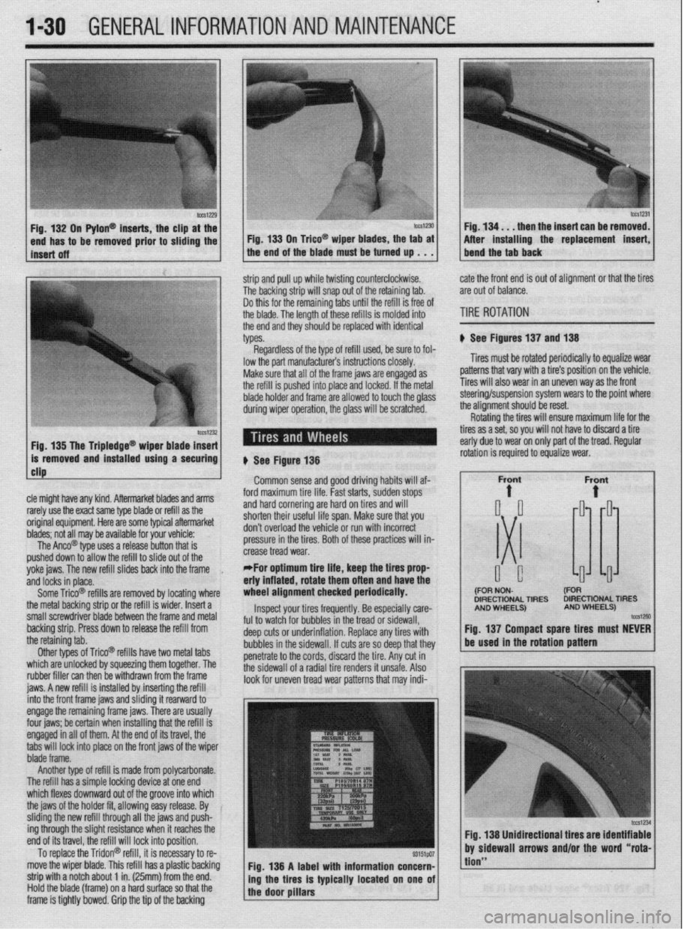
n Pylon@ inserts, the clip
be removed prior to siidi then the insert can be re
After installing the replacement
strip and pull up while twisting counterclockwise.
The backing strip will snap out of the retaining tab.
Do this for the remaining tabs until the refill is free of
the blade. The length of these refills is molded into
the end and they should be replaced with identical
types. cate the front end is out of alignment or that the tires
are out of balance.
TIRE ROTATION
# See Figures 137 and 138
Tires must be rotated periodically to equalize wear
patterns that vary with a tire’s position on the vehicle.
Tires will also wear in an uneven way as the front
1 Fin 1% Tha Trinlarlna@
cle might have any kind. Aftermarket blades and arms
rarely use the exact same type blade or refill as the
original equipment. Here are some typiel aftermarket
blades; not all may be available for your vehicle:
The Anco@ type uses a release button that is
pushed down to allow the refill to slide out of the
yoke jaws. The new refill slides back into the frame
,
and locks in place.
Some Trico@ refills are removed by locating where
the metal backing strip or the refill is wider. Insert a
small screwdriver blade between the frame and metal
backing strip. Press down to release the refill from
the retaining tab.
Other types of Trico@’ refills have two metal tabs
which are unlocked by squeezing them together. The
rubber filler can then be withdrawn from the frame
iaws. A new refill is installed bv insertina the refill lowed to touch the olass steering/suspension system wears to the point where
the alianment should be reset.
# See Figure 138
Common sense and good driving habits will af-
ford maximum tire life. Fast starts, sudden stops
and hard cornering are hard on tires and will
shorten their useful life span. Make sure that you
don’t overload the vehicle or run with incorrect
pressure in the tires. Both of these practices will in-
crease tread wear.
*For optimum tire life, keep the fires prop
eriy inflated, rotate them often and have the
wheel alignment checked periodically.
Inspect your tires frequently. Be especially care-
ful to watch for bubbles in the tread or sidewall,
deep cuts or underinflation. Replace any tires with
bubbles in the sidewall. If cuts are so deep that they
penetrate to the cords, discard the tire. Any cut in
the sidewall of a radial tire renders it unsafe. Also
look for uneven tread wear patterns that may indi- Rotating the tires will ensure maximum life for the
tires as a set, so you will not have to discard a tire
early due to wear on only part of the tread. Regular
DIRECTIONAL TIRES DIRECTIONAL TIRES
jnto the front frame jaws and &ding it rearward to
engage the remaining frame jaws. There are usually
four jaws; be certain when installing that the refill is
engaged in all of them. At the end of its travel, the
tabs will lock into place on the front jaws of the wiper
blade frame.
Another type of refill is made from polycarbonate.
The refill has a simple locking device at one end
which flexes downward out of the groove into which
the jaws of the holder fit, allowing easy release. By
sliding the new refill through all the jaws and push-
ing through the slight resistance when it reaches the
end of its travel, the refill will lock into position.
To replace the Tridon@ refill, it is necessary to re-
move the wiper blade. This refill has a plastic backing
strip with a notch about 1 in. (25mm) from the end.
Hold the blade (frame) on a hard surface so that the
frame is tightly bowed. Grip the tip of the backing Fig. 138 A label with information concern-
ing the tires is typically located on one of
the door pillars
tion”
Page 388 of 408
II-6 TROUBLESHOOTING
DIAGhUSTIC PROCEDURES
Gasoline Engines
1. Engine turns over, but wilt not start
a. Check fuel level in fuel tank, add fuel if empty.
b. Check battery condition and state of charge. If voltage and load test below specifica-
tion, charge or replace battery.
c. Check battery terminal and cable condition and tightness. Clean terminals and replace
damaged, worn or corroded cables.
d. Check fuel delivery system. If fuel is not reaching the fuel injectors, check for a loose
electrical connector or defective fuse, relay or fuel pump and replace as necessary.
e. Engine may have excessive wear or mechanical damage such as low cylinder cranking
pressure, a broken camshaft drive system, insufficient valve clearance or bent valves.
f. Check for fuel contamination such as water in the fuel. During winter months, the wa-
ter may freeze and cause a fuel restriction. Adding a fuel additive may help, however
the fuel system may require draining and purging with fresh fuel.
g. Check for ignition system failure. Check for loose or shorted wires or damaged igni-
tion system components. Check the spark plugs for excessive wear or incorrect elec-
trode gap. If the problem is worse in wet weather, check for shorts between the spark
plugs and the ignition coils.
h. Check the engine management system for a failed sensor or control module.
2. Engine does not turn over when attempting to start
a. Check the battery state of charge and condition. If the dash lights are not visible or
very dim when turning the ignition key on, the battery has either failed internally or
discharged, the battery cables are loose, excessively corroded or damaged, or the al-
ternator has failed or internally shorted, discharging the battery. Charge or replacethe
battery, clean or replace the battery cables, and check the alternator output.
b. Check the operation of the neutral safety switch. On automatic transmission vehicles,
try starting the vehicle in both Park and Neutral. On manual transmission vehicles, de-
press the clutch pedal and attempt to start. On some vehicles, these switches can be
adjusted. Make sure the switches or wire connectors are not loose or damaged. Re-
place or adjust the switches as necessary.
c. Check the starter motor, starter solenoid or relay, and starter motor cables and wires.
Check the ground from the engine to the chassis. Make sure the wires are not loose,
damaged, or corroded. If battery voltage is present at the starter relay, try using a re-
mote starter to start the vehicle for test purposes only. Replace any damaged or cor-
roded cables, in addition to replacing any failed components.
d. Check the engine for seizure. If the engine has not been started for a long period of
time, internal parts such as the rings may have rusted to the cylinder walls. The engine
may have suffered internal damage, or could be hydro-locked from ingesting water.
Remove the spark plugs and carefully attempt to rotate the engine using a suitable
breaker bar and socket on the crankshaft pulley. If the engine is resistant to moving, or
moves slightly and then binds, do not force the engine any further before determining
the problem.
3. Enpine stalls immediately when started
a. Check the ignition switch condition and operation. The electrical contacts in the run
position may be worn or damaged. Try restarting the engine with all electrical acces-
sories in the off position. Sometimes turning the key on an off will help in emergency
situations, however once the switch has shown signs of failure, it should be replaced
as soon as possible.
b. Check for loose, corroded, damaged or shorted wires for the ignition system and re-
pair or replace.
c. Check for manifold vacuum leaks or vacuum hose leakage and repair or replace parts
as necessary.
d. Measure the fuel pump delivery volume and pressure. Low fuel pump pressure can
also be noticed as a lack of power when accelerating. Make sure the fuel pump lines
are not restricted. The fuel pump output is not adjustable and requires fuel pump re-
placement to repair.
e. Check the engine fuel and ignition management system. Inspect the sensor wiring and
electrical connectors. A dirty, loose or damaged sensor or control module wire can
simulate a failed component.
f. Check the exhaust system for internal restrictions.
4. Starter motor spins, but does not engage
a. Check the starter motor for a seized or binding pinion gear.
b. Remove the flywheel inspection plate and check for a damaged ring gear.
5. Engine is difficult to start when Gold
a. Check the battery condition, battery state of charge and starter motor current draw. Re-
place the battery if marginal and the starter motor if the current draw is beyond specifi-
cation. b. Check the battery cable condition. Clean the battery terminals and replace corroded or
damaged cables.
c. Check the fuel system for proper operation. A fuel pump with insufficient fuel pressure
or clogged injectors should be replaced.
d. Check the engine’s tune-up status. Note the tune-up specifications and check for items
such as severely worn spark plugs; adjust or replace as needed. On vehicles with
manually adjusted valve clearances, check for tight valves and adjust to specification.
e. Check for a failed coolant temperature sensor, and replace if out of specification.
f. Check the operation of the engine management systems for fuel and ignition; repair or
replace failed components as necessary.
6. En#ine is ditticutt to start when hot
a. Check the air filter and air intake system. Replace the air filter if it is dirty or contami-
nated. Check the fresh air intake system for restrictions or blockage.
b. Check for loose or deteriorated engine grounds and clean, tighten or replace as
needed.
c. Check for needed maintenance. Inspect tune-up and service related items such as
spark plugs and engine oil condition, and check the operation of the engine fuel and
ignition management system.
Diesel Engines
1. Engine turns over but won’t start
a. Check engine starting procedure and restart engine.
b. Check the glow plug operation and repair or replace as necessary.
c. Check for air in the fuel system or fuel filter and bleed the air as necessary.
d. Check the fuel delivery system and repair or replace as necessary.
e. Check fuel level and add fuel as needed.
f. Check fuel quality. If the fuel is contaminated, drain and flush the fuel tank.
g. Check engine compression. If compression is below specification, the engine may
need to be renewed or replaced.
h. Check the injection pump timing and set to specification.
i. Check the injection pump condition and replace as necessary.
j. Check the fuel nozzle operation and condition or replace as necessary.
2. Engine does
hot turn over when attempting to start
a. Check the battery state of charge and condition. If the dash lights are not visible or
very dim when turning the ignition key on, the battery has either failed internally or
discharged, the battery cables are loose, excessively corroded or damaged, or the al-
ternator has failed or internally shorted, discharging the battery. Charge or replace the
battery, clean or replace the battery cables, and check the alternator output.
b. Check the operation of the neutral safety switch. On automatic transmission vehicles,
try starting the vehicle in both Park and Neutral. On manual transmission vehicles, de-
press the clutch pedal and attempt to start. On some vehicles, these switches can be
adjusted. Make sure the switches or wire connectors are not loose or damaged. Re-
place or adjust the switches as necessary.
c. Check the starter motor, starter solenoid or relay, and starter motor cables and wires.
Check the ground from the engine to the chassis. Make sure the wires are not loose,
damaged, or corroded. If battery voltage is present at the starter relay, try using a re-
mote starter to start the vehicle for test purposes only. Replace any damaged or cor-
roded cables, in addition to replacing any failed components.
d. Check the engine for seizure. If the engine has not been started for a long period of
time, internal parts such as the rings may have rusted to the cylinder walls. The engine
may have suffered internal damage, or could be hydro-locked from ingesting water.
Remove the injectors and carefully attempt to rotate the engine using a suitable
breaker bar and socket on the crankshaft pulley. If the engine is resistant to moving, or
moves slightly and then binds, do not force the engine any further before determining
the cause of the problem.
3. Engine stalls afier starting
a. Check for a restriction in the fuel return line or the return line check valve and repair as
necessary.
b. Check the glow plug operation for turning the glow plugs off too soon and repair as
necessary.
c. Check for incorrect injection pump timing and reset to specification.
d. Test the engine fuel pump and replace if the output is below specification.
e. Check for contaminated or incorrect fuel. Completely flush the fuel system and replace
with fresh fuel.
f. Test the engine’s compression for low compression. If below specification, mechanical
repairs are necessary to repair.
g. Check for air in the fuel. Check fuel tank fuel and fill as needed.
h. Check for a failed injection pump. Replace the pump, making sure to properly set the
pump timing.
Page 396 of 408
II-14 TROUBLESHOOTING
b. Check for low voltage at the bulb socket positive terminal or a poor ground. If voltage
is low, or the ground marginal, trace the wiring to, and check for loose, damaged or
corroded wires and electrical terminals; repair as necessary.
c. Check the light switch operation and replace if necessary.
1. Interior light inoperative
a. Verify the interior light switch location and position(s), and set the switch in the cor-
rect position.
b. Check for battery voltage and ground at the interior light bulb socket. If battery voltage
and ground are present, replace the bulb. If voltage is not present, check the interior
light fuse for battery voltage. If the fuse is missing, replace the fuse. If the fuse has
blown, or if battery voltage is present, refer to the wiring diagram to troubleshoot the
cause for an open or shorted circuit. If ground is not present, check the door switch
contacts and clean or repair as necessary.
2. Interior light works intermittent/y
a. Check the bulb for a damaged filament, and replace if damaged.
b. Check the bulb and bulb socket for corrosion, and clean or replace the bulb and
socket.
c. Check for loose, damaged or corroded wires and electrical terminals; repair as neces-
sary.
d. Check the door and light switch operation, and replace if necessary.
3. Interior light very dim
a. Check the bulb and bulb socket for corrosion, and clean or replace the bulb and
socket.
b. Check for low voltage at the bulb socket positive terminal or a poor ground. If voltage
is low, or the ground marginal, trace the wiring to, and check for loose, damaged or
corroded wires and electrical terminals; repair as necessary.
c. Check the door and light switch operation, and replace if necessary.
1. One brake light inoperative
a. PressPress the brake pedal and check for battery voltage and ground at the brake light
bulb socket. If present, replace the bulb. If either battery voltage or ground is not pre-
sent, refer to the wiring diagram to troubleshoot.
2. Both brake lights inoperative
a. Press the brake pedal and check for battery voltage and grou’nd at the brake light bulb
socket. If present, replace both bulbs. If battery voltage is not present, check the brake
light switch adjustment and adjust as necessary. If the brake light switch is properly
adjusted, and battery voltage or the ground is not present at the bulb sockets, or at the
bulb electrical connector with the brake pedal pressed, refer to the wiring diagram to
troubleshoot the cause of an open circuit.
3. One or both brake lights very dim
a. Press the brake pedal and measure the voltage at the brake light bulb socket. If the
measured voltage is close to the battery voltage, check for a poor ground caused by a
loose, damaged, or corroded wire, terminal, bulb or bulb socket. If the ground is
bolted to a painted surface, it may be necessary to remove the electrical connector and
clean the mounting surface, so the connector mounts on bare metal. If battery voltage
is low, check for a poor connection caused by either a faulty brake light switch, a
loose, damaged, or corroded wire, terminal or electrical connector. Refer to the wiring
diagram to troubleshoot the cause of a voltage drop.
1. Warning light(s) stay on when the engine is started
Ignition, Battery or Alternator Warning light a. Check the alternator output and voltage regulator operation, and replace as necessary.
b. Check the warning light wiring for a shorted wire.
Check Engine Light a. Check the engine for routine maintenance and tune-up status. Note the engine tune-up
specifications and verify the spark plug, air filter and engine oil condition; replace
and/or adjust items as necessary.
b. Check the fuel tank for low fuel level, causing an intermittent lean fuel mixtur
e. Top off fuel tank and reset check engine light.
c. Check for a failed or disconnected engine fuel or ignition component, sensor or con-
trol unit and repair or replace as necessary.
d. Check the intake manifold and vacuum hoses for air leaks and repair as
necessary.
e. Check the engine’s mechanical condition for excessive oil consumption.
Anti-Lock Braking System (ABS) Light a. Check the wheel sensors and sensor rings for debris, and clean as necessary.
b. Check the brake master cylinder for fluid leakage or seal failure and replace as neces-
sary.
c, Check the ABS control unit, pump and proportioning valves for proper operation; re-
place as necessary.
d. Check the sensor wiring at the wheel sensors and the ABS control unit for a loose or
shorted wire, and repair as necessary.
brake Warning Light a. Check the brake fluid level and check for possible leakage from the hydraulic lines and
seals. Top off brake fluid and repair leakage as necessary.
b. Check the brake linings for wear and replace as necessary.
c. Check for a loose or shot-ted brake warning light sensor or wire, and replace or repair
as necessary.
Oil Pressure Warning Light a. Stop the engine immediately. Check the engine oil level and oil filter condition, and
top off or change the oil as necessary.
b. Check the oil pressure sensor wire for being shorted to ground. Disconnect the wire
from the oil pressure sensor and with the ignition in the ON position, but not running,
the oil pressure light should not be working. If the light works with the wire discon-
nected, check the sensor wire for being shorted to ground. Check the wire routing to
make sure the wire is not pinched and check for insulation damage. Repair or replace
the wire as necessary and recheck before starting the engine.
c. Remove the oil pan and check for a clogged oil pick-up tube screen.
d. Check the oil pressure sensor operation by substituting a known good sensor.
e. Check the oil filter for internal restrictions or leaks, and replace as necessary.
WARNING: If the engine is operated with oil pressure below the manufac-
turer’s specification, severe (and costly) engine damage could occur. Low
oil pressure can be caused by excessive internal wear or damage to the en-
gine bearings, oil pressure relief valve, oil pump or oil pump drive mecha-
nism.
Before starting the engine, check for possible causes of rapid oil loss, such as leaking
oil lines or a loose, damaged, restricted, or leaking oil filter or oil pressure sensor. If the
engine oil level and condition are acceptable, measure the engine’s oil pressure using a
pressure gauge, or determine the cause for the oil pressure warning light to function
when the engine is running, before operating the engine for an extended period of time.
Another symptom of operating an engine with low oil pressure is the presence of severe
knocking and tapping noises.
Parking Brake Warning Light a. Check the brake release mechanism and verify the parking brake has been fully re-
leased.
b. CheckCheck the parking brake light switch for looseness or misalignment.
c. CheckCheck for a damaged switch or a loose or shorted brake light switch wire, and
replace or repair as necessary.
2. Warning light(s) flickers on and off when driving
Ignition, Battery or Alternator Warning Light a. Check the alternator output and voltage regulator operation. An intermittent condition
may indicate worn brushes, an internal short, or a defective voltage regulator. Replace
the alternator or failed component.
b. Check the warning light wiring for a shorted, pinched or damaged wire and repair as
necessary.
Check Engine Light a. Check the engine for required maintenance and tune-up status. Verify engine tune-up
specifications, as well as spark plug, air filter and engine oil condition; replace and/or
adjust items as necessary.
b. Check the fuel tank for low fuel level causing an intermittent lean fuel mixture. Top off
fuel tank and reset check engine light.
c. Check for an intermittent failure or partially disconnected engine fuel and ignition
component, sensor or control unit; repair or replace as necessary.
d. Check the intake manifold and vacuum hoses for air leaks, and repair as necessary.
e. Check the warning light wiring for a shorted, pinched or damaged wire and repair as
necessary.
Anti-Lock Braking System (ABS) Light a. Check the wheel sensors and sensor rings for debris, and clean as necessary.
b. Check the brake master cylinder for fluid leakage or seal failure and replace as neces-
sary.
c. Check the ABS control unit, pump and proportioning valves for proper operation, and
replace as necessary.
Page 402 of 408
II-20 GLOSSARY
SECONDARY CIRCUIT: The high voltage side of the ignition system, usu-
ally above 20,000 volts. The secondary includes the ignition coil, coil wire,
distributor cap and rotor, spark plug wires and spark plugs.
SENDING UNIT: A mechanical, electrical, hydraulic or electromagnetic de-
vice which transmits information to a gauge.
SENSOR: Any device designed to measure engine operating conditions or
ambient pressures and temperatures. Usually electronic in nature and designed
to send a voltage signal to an on-board computer, some sensors may oper-
ate as a simple on/off switch or they may provide a variable voltage signal
(like a potentiometer) as conditions or measured parameters change.
SHIM: Spacers of precise, predetermined thickness used between parts to es-
tablish a proper working relationship.
SLAVE CYLINDER: In automotive use, a device in the hydraulic clutch sys-
tem which is activated by hydraulic force, disengaging the clutch.
SOLENOID: An electrically operated, magnetic switching device.
SPARK PLUG: A device screwed into the combustion chamber of a spark ig-
nition engine. The basic construction is a conductive core inside of a ceramic
insulator, mounted in an outer conductive base. An electrical charge from the
spark plug wire travels along the conductive core and jumps a preset air gap
to a grounding point or points at the end of the conductive base. The resul-
tant spark ignites the fuel/air mixture in the combustion chamber.
SPLINES: Ridges machined or cast onto the outer diameter of a shaft or in-
ner diameter of a bore to enable parts to mate without rotation.
TACHOMETER: A device used to measure the rotary speed of an engine,
shaft, gear, etc., usually in rotations per minute.
THERMOSTAT: A valve, located in the cooling system of an engine, which
is closed when cold and opens gradually in response to engine heating, con-
trolling the temperature of the coolant and rate of coolant flow.
TOP DEAD CENTER (TDC): The point at which the piston reaches the top
of its travel on the compression stroke.
TORQUE: Measurement of turning or twisting force, expressed as foot-pounds
or inch-pounds.
TORQUE CONVERTER: A turbine used to transmit power from a driving
member to a driven member via hydraulic action, providing changes in drive
ratio and torque. In automotive use, it links the driveplate at the rear of the en-
gine to the automatic transmission. TRANSDUCER: A device that changes energy from one form to another. For
example, a transducer in a microphone changes sound energy to electrical en-
ergy. In automotive air-conditioning controls used in automatic temperature
systems, a transducer changes an electrical signal to a vacuum signal, which
operates mechanical doors.
TRANSISTOR: A semi-conductor component which can be actuated by a
small voltage to perform an electrical switching function.
TUNE-UP: A regular maintenance function, usually associated with the re-
placement and adjustment of parts and components in the electrical and fuel
systems of a vehicle for the purpose of attaining optimum performance.
TURBOCHARGER: An exhaust driven pump which compresses intake air
and forces it into the combustion chambers at higher than atmospheric pres-
sures The increased air pressure allows more fuel to be burned and results
in increased horsepower being produced.
.
VACUUM ADVANCE: A device which advances the ignition timing in re-
sponse to increased engine vacuum.
VACUUM GAUGE: An instrument used for measuring the existing vacuum
in a vacuum circuit or chamber. The unit of measure is inches (of mercury in
a barometer).
VALVE: Devices that can open or close fluid passages in a hydraulic system
and are used for directing fluid flow and controlling pressure.
VALVE CLEARANCE: The measured gap between the end of the valve stem
and the rocker arm, cam lobe or follower that activates the valve.
VISCOSITY: The ability of a fluid to flow. The lower the viscosity rating, the
easier the fluid will flow. 10 weight motor oil will flow much easier than 40
weight motor oil.
VOLTMETER: An instrument used for measuring electrical force in units
called volts. Voltmeters are always connected parallel with the circuit being
tested.
WHEEL CYLINDER: Found in the automotive drum brake assembly, it is a
device, actuated by hydraulic pressure, which, through internal pistons, pushes
the brake shoes outward against the drums.