low beam MITSUBISHI DIAMANTE 1900 Repair Manual
[x] Cancel search | Manufacturer: MITSUBISHI, Model Year: 1900, Model line: DIAMANTE, Model: MITSUBISHI DIAMANTE 1900Pages: 408, PDF Size: 71.03 MB
Page 4 of 408
I-4 GENERALINFORMATIONAND MAINTENANCE
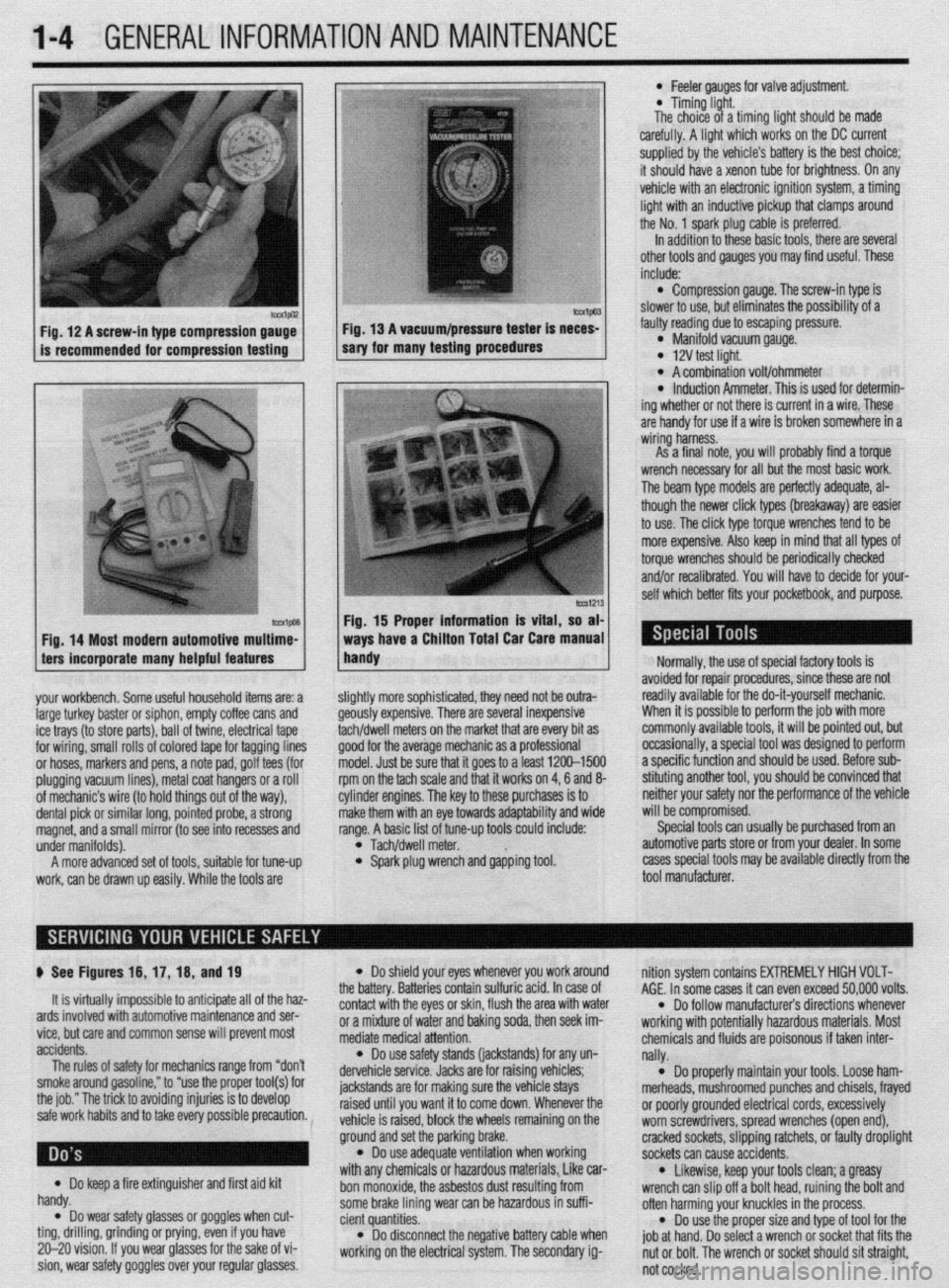
Fig. 12 A screw-in type compression gauge- Fig. 13 A vacuum/pressure tester is neces-
is recommended for compression testing sary for many testing procedures
Fig. 14 Most modern automotive multime-
ters incorporate many helpful features
your workbench. Some useful household items are: a
large turkey baster or siphon, empty coffee cans and
ice trays (to store parts), ball of twine, electrical tape
for wiring, small rolls of colored tape for tagging lines
or hoses, markers and pens, a note pad, golf tees (for
plugging vacuum lines), metal coat hangers or a roll
of mechanic’s wire (to hold things out of the way),
dental pick or similar long, pointed probe, a strong
magnet, and a small mirror (to see into recesses and
under manifolds).
A more advanced set of tools, suitable for tune-up
work, can be drawn up easily. While the tools are
lmvl Fig. 15 Proper information is vital, so at
ways have a Chiiton Total Car Care manua
handy
l Feeler aauoes for valve adiustment
* Timing-light.
The choice of a timing fight should be made
carefully. A light which works on the DC current
supplied by the vehicle’s battery is the best choice;
it should have a xenon tube for brightness. On any
vehicle with an electronic ignition system, a timing
light with an inductive pickup that clamps around
the No. 1 spark plug cable is preferred.
In addition to these basic tools, there are several
other tools and gauges you may find useful. These
include:
l Compression gauge. The screw-in type is
slower to use, but eliminates the possibility of a
fauliy reading due to escaping pressure.
l Manifold vacuum gauge. l 12V test light. l A combination volt/ohmmeter l induction Ammeter. This is used for determin-
ing whether or not there is current in a wire. These
are handy for use if a wire is broken somewhere in a
wiring harness.
As a final note, vou will orobablv find a torque
wrench necessary for all but the most basic work.
The beam type models are perfectly adequate, al-
though the newer click types (breakaway) are easier
to use. The click type torque wrenches tend to be
more expensive. Also keep in mind that all types of
torque wrenches should be periodically checked
and/or recalibrated. You will have to decide for your-
self which better fits your pocketbook, and purpose.
ilightly more sophisticated, they need not be outra-
feously expensive. There are several inexpensive
achldwell meters on the market that are every bit as
Toad for the average mechanic as a professional
nodel. Just be sure that it goes to a least 1200-1500
pm on the tach scale and that it works on 4,6 and 8-
:ylinder engines. The key to these purchases is to
nake them with an eye towards adaptability and wide
ange. A basic list of tune-up tools could include:
l Tach/dwell meter. l Spark plug wrench and gapping tool. Normally, the use of special factory tools is
avoided for repair procedures, since these are not
readily available for the do-it-yourself mechanic.
When it is possible to perform the job with more
commonly available tools, it will be pointed out, but
occasionally, a special tool was designed to perform
a specific function and should be used. Before sub-
stituting another tool, you should be convinced that
neither your safety nor the performance of the vehicle
will be compromised.
Special tools can usually be purchased from an
automotive parts store or from your dealer. In some
cases special tools may be available directly from the
tool manufacturer.
p See Figures 16, 17, 16, and 19
It is virtually impossible to anticipate all of the haz-
ards involved with automotive maintenance and ser-
vice, but care and common sense will prevent most
accidents.
The rules of safety for mechanics range from “don’t
smoke around gasoline,” to “use the proper tool(s) for
the job.” The trick to avoiding injuries is to develop
safe work habits and to take every possible precaution.
Do keep a fire extinguisher and first aid kit
l handy.
Do wear safety glasses or goggles when cut- l ting, drilling, grinding or prying, even if you have
20-20 vision. If you wear glasses for the sake of vi-
sion, wear safety goggles over your regular glasses.
l Do shield your eyes whenever you work around
the battery. Batteries contain sulfuric acid. In case of
contact with the eyes or skin, flush the area with water
or a mixture of water and baking soda, then seek im-
mediate medical attention.
l Do use safety stands (jackstands) for any un-
dervehicle service. Jacks are for raising vehicles;
jackstands are for making sure the vehicle stays
raised until you want it to come down. Whenever the
vehicle is raised, block the wheels remaining on the
ground and set the parking brake.
l Do use adequate ventilation when working
with any chemicals or hazardous materials, Like car-
bon monoxide, the asbestos dust resulting from
some brake lining wear can be hazardous in suffi-
cient quantities.
l Do disconnect the negative battery cable when
working on the electrical system. The secondary ig- nition system contains EXTREMELY HIGH VOLT-
AGE. In some cases it can even exceed 50,000 volts.
l Do follow manufacturer’s directions whenever
working with potentially hazardous materials. Most
chemicals and fluids are poisonous if taken inter-
nally.
l Do properly maintain your tools. Loose ham-
merheads, mushroomed punches and chisels, frayed
or poorly grounded electrical cords, excessively
worn screwdrivers, spread wrenches (open end),
cracked sockets, slipping ratchets, or faulty droplight
sockets can cause accidents.
* Likewise, keep your tools clean; a greasy
wrench can slip off a bolt head, ruining the bolt and
often harming your knuckles in the process.
l Do use the proper size and type of tool for the
job at hand. Do select a wrench or socket that fits the
nut or bolt. The wrench or socket should sit straight,
not cocked.
Page 7 of 408
.
l-8 GENERALINFORMATIONAND MAINTENANCE
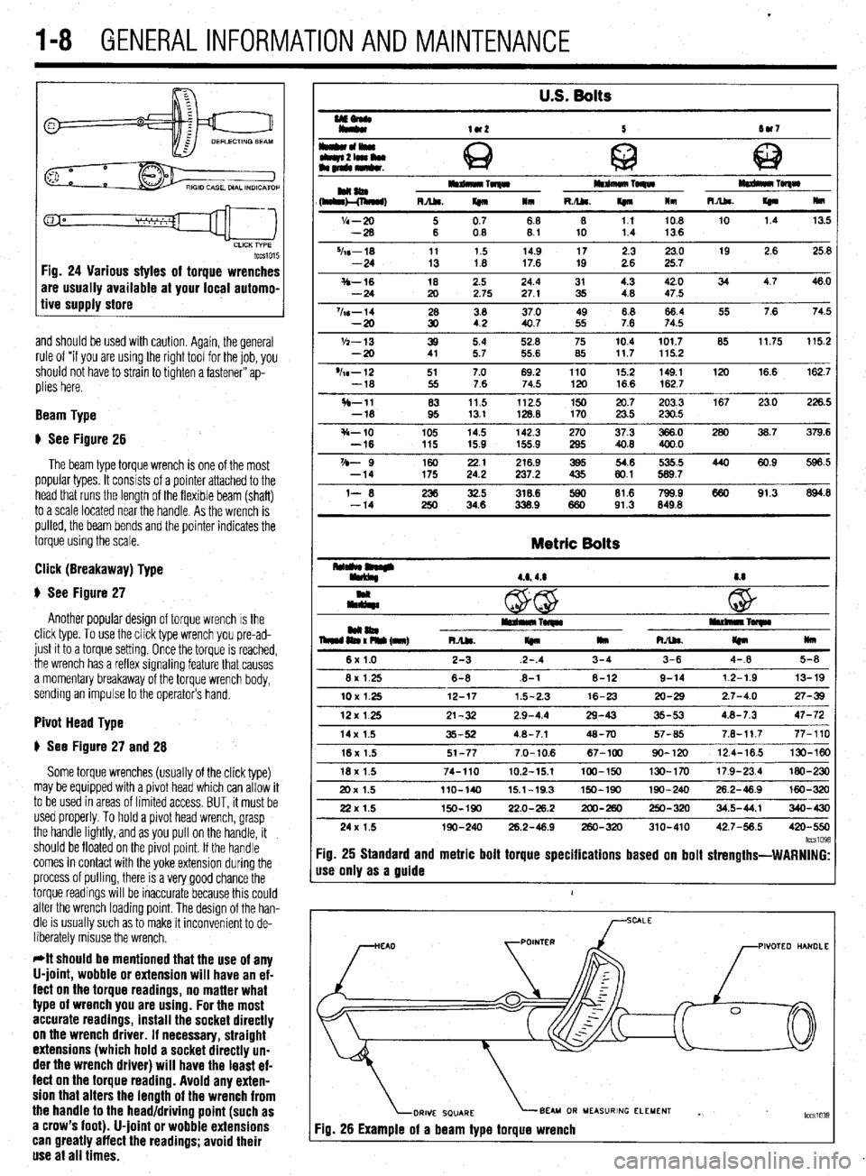
tccsio15 Fig. 24 Various styles of torque wrenches
are usually available at your local automo-
tive supply store
and should be used with caution. Again, the general
rule of “if you are using the right tool for the job, you
should not have to strain to tighten a fastener” ap-
plies here.
Beam Type
# See Figure 26
The beam type torque wrench is one of the most
popular types. It consists of a pointer attached to the
head that runs the length of the flexible beam (shaft)
to a scale located near the handle. As the wrench is
pulled, the beam bends and the pointer indicates the
torque using the scale.
Click (Breakaway) Type
$ See Figure 27
Another popular design of torque wrench IS the
click type. To use the click type wrench you pre-ad-
just it to a torque setting. Once the torque is reached,
the wrench has a reflex signaling feature that causes
a momentary breakaway of the torque wrench body,
sending an impulse to the operator’s hand.
Pivot Head Type
# See Figure 27 and 28
Some torque wrenches (usually of the click type)
may be equipped with a pivot head which can allow it
to be used in areas of limited access. BUT, it must be
used properly. To hold a pivot head wrench, grasp
the handle lightly, and as you pull on the handle, it
should be floated on the pivot point. If the handle
comes in contact with the yoke extension during the
process of pulling, there is a very good chance the
torque readings will be inaccurate because this could
alter the wrench loading point. The design of the han-
dle is usually such as to make it inconvenient to de-
liberately misuse the wrench.
*It should be mentioned that the use of any
U-joint, wobble or extension will have an ef-
fect on the torque readings, no matter what
type of wrench you are using. For the most
accurate readings, install the socket directly
on the wrench driver. If necessary, straight
extensions (which hold a socket directly un-
der the wrench driver) will have the least ef-
fect on the torque reading. Avoid any exten-
sion that alters the length of the wrench from
the handle to the head/driving point (such as
a crow’s foot). U-joint or wobble extensions
can greatly affect the readings; avoid their
use at all times.
U.S. Bolts
UEonlr
Iy*
lU2 5 tw7
I*cll*olwu
Q c
tbqn2lamlu
am~mkr. @ 63
HaaIm Toqw mdmuo TORW
(h&l!&, RA&. m 111 R./U. If410 lm m TolqW
R.Abs.
I(n Hm
'I4 - 20 i 0.7 68 8 1.1 10.8 10 1.4 13.5
-28 08 8.1 10 1.4 13.6
%s-18 11 1.5 14.9 17 2.3 23.0 19 2.6 25.8
-24 13 1.8 17.6 19 2.6 25.7
S-16 18 2.5 24.4 31 4.3 42.0 34 4.7 46.0
-24 20 2.75 27.1 35 4.8 47.5
%s-14 28 3.8 37.0 49 8.8 66.4 55 7.6 74.5
-20 30 42 40.7 55 7.6 74.5
'h-13 39 5.4 52.8 75 10.4 101.7 85 11.75 115.2
-20 41 5.7 55.6 85 117 115.2
'h-12 51 7.0 69.2 110 15.2 149.1 120 16.6 162.7
-18 55 7.6 74.5 120 16.6 162.7
H-11 83 11.5 112.5 150 20.7 203.3 167 23.0 226.5
-18 95 13.1 128.8 170 23.5 230.5
s-10 105 14.5 142.3 270 37.3 366.0 280 36.7 379.6
-16 115 15.9 155.9 295 40.8 400.0
VD- 9 160 2.: 216.9 395 54.6 535.5 440 60.9 596.5
-14 175 237.2 435 80.1 589.7
l- 6 iti 32.5 318.6 lE 81.6 799.9 660 91.3 894.8
-14 34.6 338.9 91.3 849.8
Metric Bolts
4.6,4.8 8.8
c
@ w
mm04 iEn% (nnr) I*rdn*lrTwlr rullllllnl~
RJU.
I(n llm RAk
m mu
6x1.0 2-3 2-.4 3-4 3-6 4-.8 5-8
8x 1.25 6-8 .6-l 8-12 9-14 12-1.9 13-19
10X1.25 12-17 1.5-2.3 16-23 20-29 2.7-4.0 27-39
12x125 21-32 2.9-4.4 29-43 35-53 4.8-7.3 47-72
14x 1.5 35-52 4.8-7.1 48-70 57-65 7.8-11.7 77-110
16x 1.5 51-77 7.0-10.6 67-100 90-120 12.4-16.5 130-W
18x 1.5 74-110 10.2-15.1 100-150 130-170 17.9-23.4 MO-230
20x 1.5 llO-140 15.1-19.3 150-190 190-240 26.2-46.9 160-320
22x 1.5 150-190 22.0-26.2 200-260 250-320 34.5-44.1 340-430
24x 1.5 190-240 26.2-48.9 260-320 310-410 42.7-56.5 420-550
lccs1098 :ig. 25 Standard and metric bolt torque specifications based on bolt strengths-WARNING:
Ise only as a guide
1
PIVOTEO HANDLE
BEAU OR MEASURING ELEMENT
Yg. 26 Example of a beam type torque wrench . tccslo3~
Page 56 of 408
ENGlNEELECTRldAL 2-9
TESTING
Voltage Test able for use by customers. An alternator
bench test is the most definitive way to de-
termine the condition of your alternator.
REMOVAL&INSTALLATION
1. Make sure the engine is OFF, and turn the 1.51,1.61, 1.6L, 2.OL and 2.4L Engines
headlights on for 15-20 seconds to remove any sur-
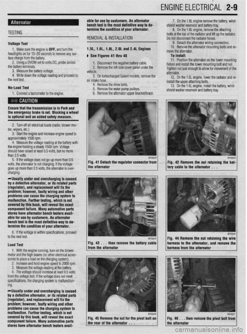
face charge from the battery. , See Figures 4, thru 48
2. Using a DVOM set to volts DC, probe across
1. Disconnect the negative battery cable.
the battery terminals.
3. Measure the battery voltage. 2. Remove the left side cover panel under the
vehicle.
4. Write down the voltage reading and proceed to
3. On turbocharaed Galant models, remove the
the next test.
air intake hose. -
No-load Test
1. Connect a tachometer to the engine. 4. Remove the drive belts.
5. Remove the water pump pulleys.
6. Remove the alternator upper bracket/brace.
Ensure that the transmission
is in Park and the emergency brake is set. Blocking a wheel
is optional and an added safety measure.
2. Turn off all electrical loads (radio, blower mo-
tor, wipers, etc.)
3. Start the engine and increase engine speed to
approximately 1500 rpm.
4. Measure the voltage reading at the battery with
the engine holding a steady 1500 rpm. Voltage
should have raised at least 0.5 volts, but no more
than 2.5 volts.
5. If the voltage does not go up more than 0.5
volts, the alternator is not charging. If the voltage
goes up more than 2.5 volts, the alternator is over-
* 7. On the 1.6L engine remove the battery, wind-
shield washer reservoir and battery tray.
8. On the 1.6L engine, remove the attaching
bolts at the top of the radiator and lift up the radiator.
Do not disconnect the radiator hoses.
9. Detach the alternator wiring connectors.
10. Remove the alternator mounting bolts and re-
move the alternator.
To install:
11. Position the alternator on the lower mountina
fixture and install the lower mounting bolt and nut. U
Tighten nut just enough to allow for movement of the
alternator.
12. On the 1.6L engine, lower the radiator and re-
install the upper attaching bolts.
13. On the 1.6L engine, install the battery, wind-
shield washer reservoir and battery tray.
/ tery cable to the alternator . , . 93152p12 Fig 42 Remove the nut retaining the bat-
cnargmg.
*Usually under and overcharging is‘caused
by a defective alternator, or its related parts
(regulator), and replacement will fix the
problem; however, faulty wiring and other
problems can
cause the charging system to
malfunction. Further testing, which is not
covered by this book, will reveal the exact
component failure. Many automotive parts
stores have alternator bench testers avaii-
able for use by customers. An alternator
bench test is the most definitive way to de-
termine the condition of your alternator.
6. If the voltage is within specifications, proceeU
to the next test.
Load Test
1. With the engine running, turn on the blower
motor and the hioh beams (or other electrical acces-
sories to place aioad on the charging system). Fig. 44 Remove the nut retaining the
then remove the batte harness to the alternator and remov
,
2. Increase and hold engine speed to 2000 rpm.
3. Measure the voltage reading at the battery.
4. The voltage should increase at least 0.5 volts
from the voltage test. If the voltage does not meet
specifications, the charging system is malfunction-
ing.
*Usually under and overcharging is caused
by a defective alternator, or its related parts
(regulator), and replacement will fix the
problem; however, faulty wiring and other
problems can cause the charging system to
malfunction. Further testing, which is not
covered by this book, will reveal the exact
component failure. Many automotive parts
stores have alternator bench testers avaii-
93152p17 en remove the pivot bolt from
Page 200 of 408
FUELSYSTiM 5-13
1. BODY HARNESS CONNECTION
2 HOSE CONNECTION
3 PURGE HOSE
4 VAPOR HOSE
5 VENT HOSE
6 FllLER HOSE
7 PIPE ASSEMBLY
8. BAND ASSEMBLY
9 FUEL TANK ASSEMBLY
10. DIFFERENTIAL PRESSURE
SENSOR
11 FUEL HARNESS
12 HIGH-PRESSURE FUEL HOSE 1; ;;JL RETURN HOSE
15 FUEL PUMP MODULE
16 FILLER NECK
17 FUEL CAP
IS REINFORCEMENT
19 PACKING
20 VAPOR HOSE
21 SEPARATOR ASSEMBLY
22 VAPOR HOSE
23 FUEL CHECK VALVE ASSEMBLY
24 FUEL FILLER NECK ASSEMBLY
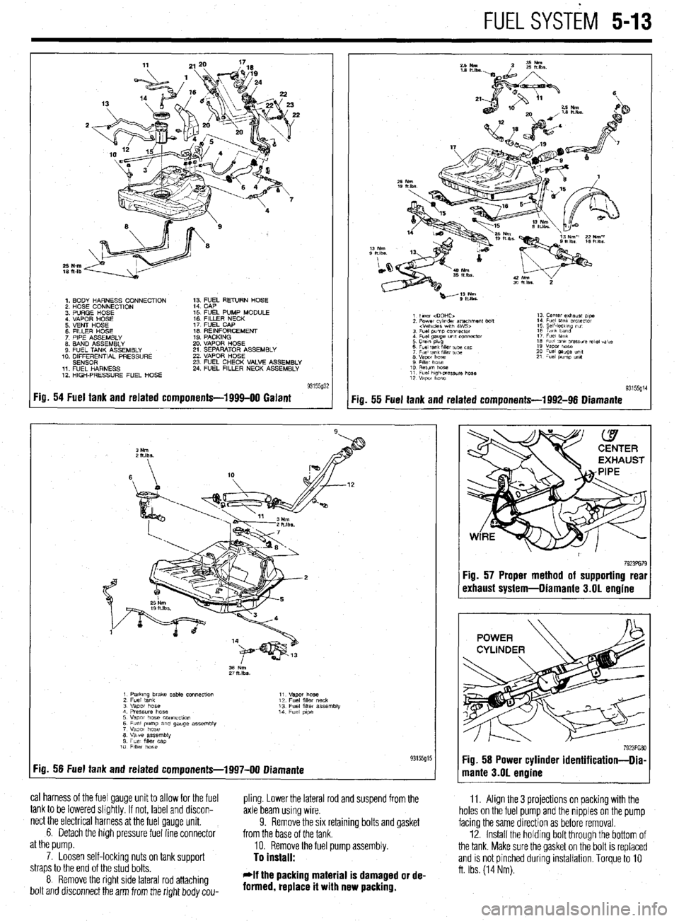
Fig. 54 Fuel tank and related components-1999-00 Galant
:ia. 55 Fuel tank and related components-1992-96 Diamante
11. Align the 3 projections on packing with the
holes on the fuel pump and the nipples on the pump
facing the same direction as before removal.
12. Install the holdrng bolt through the bottom of
the tank. Make sure the gasket on the bolt is replaced
and is not pinched during installation. Torque to 10
ft. Ibs. (14 Nm).
1 PatkIng brake cable COnneCtlo” 11
2 Fuel tank “.qm hose
12 Fuel fllk, neck
3 “apot hose 13 Fuel filler assembly
4 Pressure hose 14
5 Vapor hose COnneCflOn Fuel p,pe
6 Fuel pump am gauge assembly
7 Vapor hose
8 Valve assembly
9 Fuel mer cap
10 FllkY hose
:ig. 56 Fuel tank and related components-1997-00 Diamante 93155g15
cal harness of the fuel gauge unit to allow for the fuel
pling. Lower the lateral rod and suspend from the
tank to be lowered slightly. If not, label and discon-
axle beam using wire.
nect the electrical harness at the fuel gauge unit.
6. Detach the high pressure fuel line connector 9. Remove the six retaining bolts and gasket
from the base of the tank.
at the pump.
10. Remove the fuel pump assembly.
7. Loosen self-lockinq nuts on tank suooort
To install: straps to the end of the stud bolts.
8 Remove the right side lateral rod attaching
bolt and drsconnect the arm from the right body cou- *If the packing material is damaged or de-
formed, replace it with new packing.
7923PG79 :ig. 57 Proper method of supporting real
rxhaust system-Diamante 3.01 engine
Page 222 of 408
CHASSIS ELECTRICAL 6-19
1. Disconnect the negative battery cable.
are all built into 1 multi-function combination
2. Remove the instrument cluster, as outlined 1. Disconnect the negative battery cable.
earlier in this section. switch that is mounted on the steering col-
2. Using a small screwdriver or other suitable
umn. Refer to Section 8 for procedures re-
3. Remove the retaining screws for the instrument tool, carefully pry the retaining clips from either side
garding the combination switch.
cluster lens and cover assembly. Remove the cover of the switch trim plate.
3.
and lens. Carefully pull the switch and trim plate out of
,
4. Remove the retaining screws for the gauge or the instrument panel.
4. Detach the electrical connectors and remove
warning lamp to be replaced, then remove the gauge
the switch.
or warning lamp.
REMOVAL&INSTALLATION : 5. The installation is the reverse of removal.
To install:
5. Place the gauge or warning lamp into place
and tighten the retaining screws. 1. Disconnect the negative battery cable.
6. Install the instrument cluster lens and cover 2. Using a suitable prytool, disengage the switch
assembly. retaining tabs.
REMOVAL &INSTALLATION 7. Install the instrument cluster. 3. Gently pull the switch from the instrument
8. Connect the negative battery cable. panel.
4. Detach the electrical connector and remove the *On all models the headlights, turn signals,
switch. and on some models, the cruise control func-
5. The installation is the reverse of removal. tion are all built into 1 multi-function combi-
nation switch that is mounted on the steerinq
REMOVAL &INSTALLATION column. Refer to Section 8 for procedures 6
garding the combination switch.
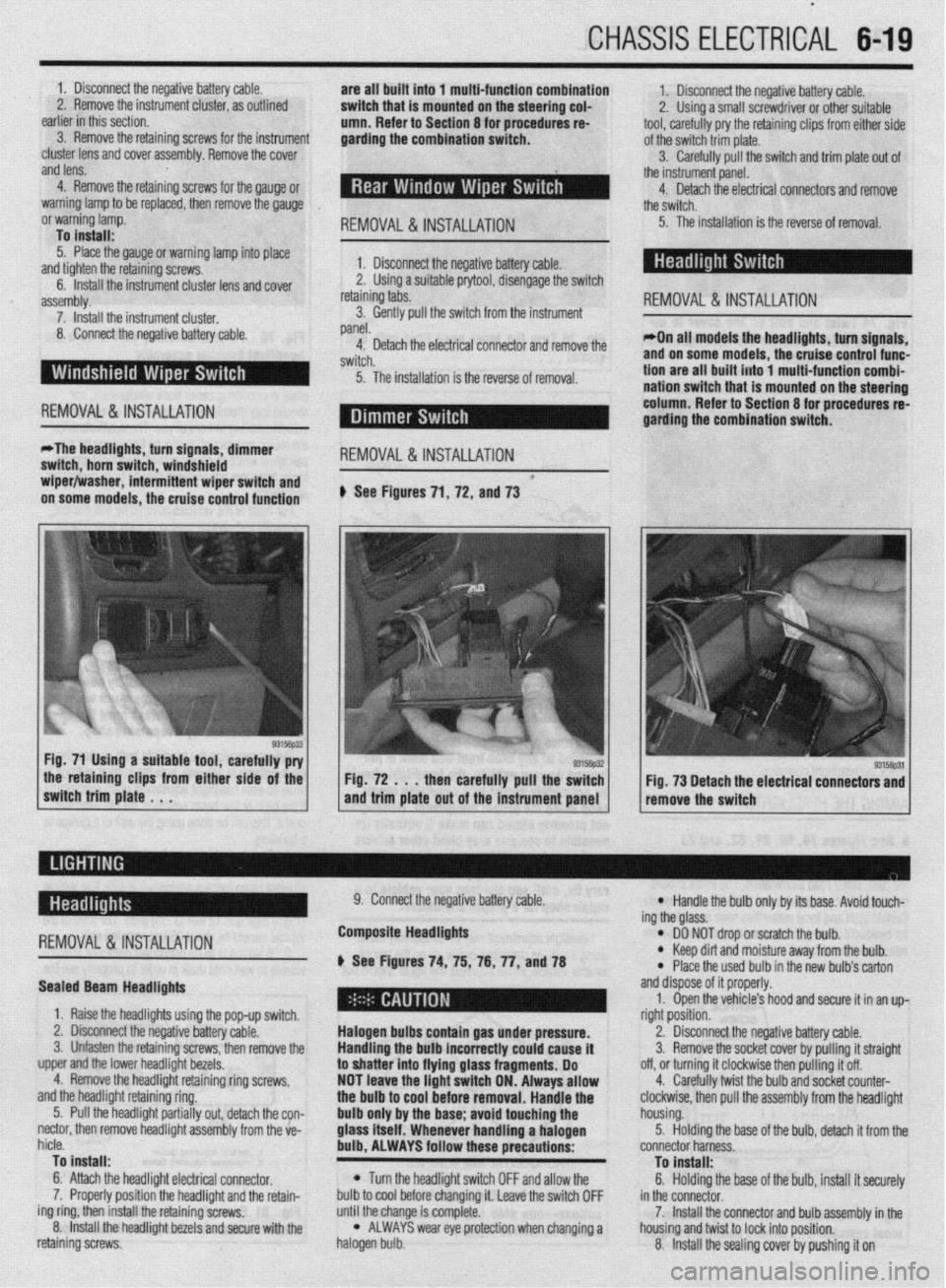
*The headlights, turn signals, dimmer
switch, horn switch, windshield
REMOVAL &INSTALLATION
wiper/washer, intermittent wiper switch and *
on some models, the cruise control function # See Figures 71, 72, and 73
the retaining clips from either side of the
switch trim plate . . . Fig. 72 . . . then carefully pull the switch
and trim plate out of the instrument panel Fig. 73 Detach the electrical connectors and
remove the switch
-
REMOVAL &INSTALLATION
Sealed Beam Headlights
1. Raise the headlights using the pop-up switch.
2. Disconnect the negative battery cable.
3. Unfasten the retaining screws, then remove the
upper and the lower headlight bezels.
4. Remove the headlight retaining ring screws,
and the headlight retaining ring.
5. Pull the headlight partially out, detach the con-
nectar, then remove headlight assembly from the ve-
hicle.
To install:
6. Attach the headlight electrical connector.
7. Properly position the headlight and the retain-
ing ring, then install the retaining screws.
8. Install the headlight bezels and secure with the
retaining screws. 9. Connect the negative battery cable.
Composite Headlights
6 See Figures 74, 75, 76, 77, anU78
Halogen bulbs contain gas under pressure.
Handling the
bulb incorrectly could cause it
to shatter into flying glass fragments. Do
NOT leave the light switch ON. Always allow
the bulb to cool before removal. Handle the
bulb only by the base; avoid touching the
glass itself. Whenever handling a halogen
bulb, ALWAYS follow these precautions:
l Turn the headlight switch OFF and allow the
bulb to cool before changing it. Leave the switch OFF
until the change is complete.
l ALWAYS wear eye protection when changing a
halogen bulb.
l Handle the bulb only by its base. Avoid touch-
ing the glass.
l DO NOT drop or scratch the bulb. l Keep dirt and moisture away from the bulb.
* Place the used bulb in the new bulb’s carton
and dispose of it properly.
1. Open the vehicle’s hood and secure it in an up-
right position.
2. Disconnect the negative battery cable.
3. Remove the socket cover by pulling it straight
off, or turning it clockwise then pulling it off.
4. Carefully twist the bulb and socket counter-
clockwise, then pull the assembly from the headlight
housing.
5. Holding the base of the bulb, detach it from the
connector harness.
To install:
6. Holding the base of the bulb, install it securely
in the connector.
7. Install the connector and bulb assembly in the
housing and twist to lock into position.
8. Install the sealing cover by pushing it on
Page 223 of 408
.
6-20 CHASSIS ELECTRICAL
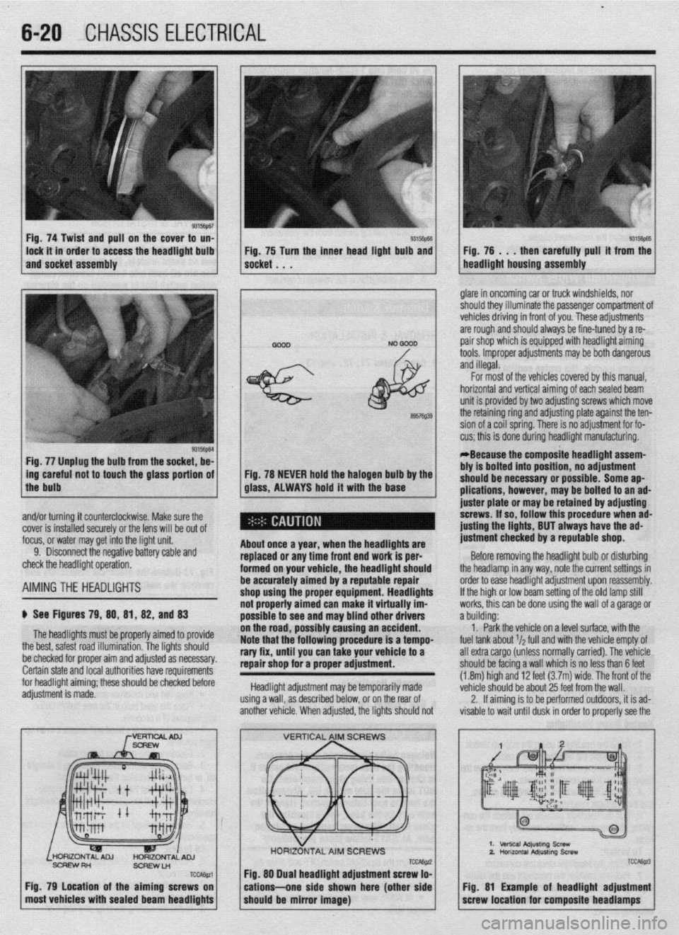
Fig. 74 Twist and pull on the cover to un-
lock it in order to access the headlight bulb
and socket assembly 93Mm Fig, 75 Turn the inner head light bulb and then carefully pull’ it from the
NO 0000 . glare in oncoming car or truck windshields, nor
should they illuminate the passenger compartment of
vehicles driving in front of you. These adjustments
are rough and should always be fine-tuned by a re-
pair shop which is equipped with headlight aiming
tools. Improper adjustments may be both dangerous
and illegal.
Fig. 77 Unplug the bulb from the socket, be-
L
ing careful not to touch the glass portion of
the bulb
I
6957Q39
Fig. 78 NEVER hold the halogen bulb by the
glass, ALWAYS hold it with the base
,
About once a year, when the headllgftts are
replaced or any time front end work is per-
formed on your vehicle, the headlight should
be accurately aimed by a reputable repair
shop uslng the proper equipment. Headlights
not properly aimed can make it virtually im-
possible to see ar Id may blind other drivers
ibly causing an accident.
Note that the’following procedure is a tempo-
rary fix, until you can take your vehicle to a
repair shop for a proper adjustment.
Headlight adjustment may be temporarily made
using a wall, as described below, or on the rear of
another vehicle. When adjusted, the lights should not For most of the vehicles covered by this manual,
horizontal and vertical aiming of eachsealed beam
unit is provided by two adjusting screws which move
the retaining ring and adjusting plate against the ten-
sion of a coil spring. There is no adjustment for fo-
cus; this is done during headlight manufacturing.
*Because the composite headlight assem-
bly is bolted into position, no adjustment
should be necessary or possible. Some ap-
plications, however, may be bolted to an ad-
juster plate or may be retained by adjusting
screws. If so, follow this procedure when ad-
@sting the lights, BUT always have the ad-
justment checked by a reputable shop.
Before removing the headlight bulb or disturbing
the headlamp in any way, note the current settings in
order to ease headlight adjustment upon reassembly.
If the high or low beam setting of the old lamp still
works, this can be done using the wall of a garage or
a building:
1. Park the vehicle on a level surface, with the
fuel tank about r/a full and with the vehicle empty of
all extra cargo (unless normally carried). The vehicle
should be facing a wall which is no less than 6 feet
(1.8m) high and 12 feet (3.7m) wide. The front of the
vehicle should be about 25 feet from the wall.
2. If aiming is to be performed outdoors, it is ad-
visable to wait until dusk in order to properly see the
% and/or turning it counterclockwise. Make sure the
cover is installed securely or the lens will be out of
focus, or water may get into the light unit.
9. Disconnect the negative battery cable and
check the headlight operation.
AIMINGTHE HEADLIGHTS
$ See Figures 79, 88, 81, 82, and 83
The headlights must be proper’ ’ ’ ’
the best, safest road illumination. ’ ’
ly armea IO provrae
The lights should
:.__1__1 __ - -___-_-. on the road, POSSI
be checked for proper aim and adfusreu as IlweSYdly. Certain state and local authorities have requirements
for headlight aiming; these should be checked before
adjustment is made.
SCFEWRH
ScFlEwLn
TCcAssa
Fig. 79 Location of the aiming screws on
most vehicles with sealed beam headlights
TCCAE@ Fig. 88 Dual headlight adjustment screw lo-
cations--one side shown here (other side
should be mirror image)
2.
TCC&z3
Fig. 81 Example of headlight adjustment
screw location for composite headlamps
Page 224 of 408
CHASSIS ELECTRICAL 6-21
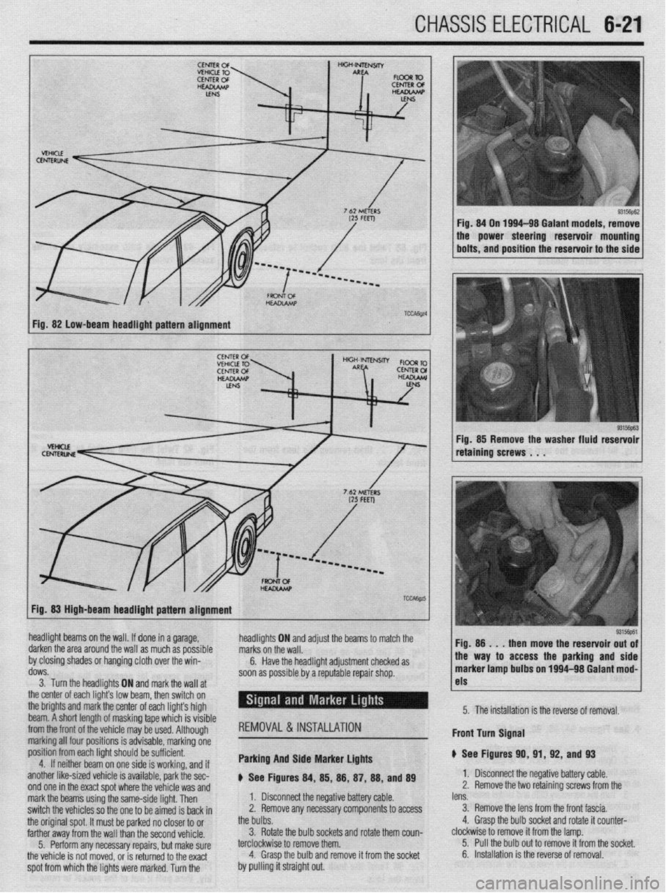
Fig. 82 low-beam headlight pattern alignment
93156pE.3 Fig. 85 Remove the washer fluid reservoir
retaining screws . . .
Fig. 83 High-beam headlight pattern alignment
headlight beams on the wall. If done in a garage,
darken the area around the wall as much as possible
by closing shades or hanging cloth over the win-
dows.
3. Turn the headlights ON and markthe wall at
the center of each light’s low br ram, then switch on
the brights and mark the center of each lights high
beam. A short length of maskin g tape which is visible
from the front of the
whir+ ma . ._..._._ . .._ y be used. Although
marking all four po:
sitions is advisable, marking one
position from each
light should be sufficient.
4. If neithar he; ~. __
Irn on one side is working, and if
another like-sized vehicle is available, park the sec-
nnri nm in the wart cnnt whrw the whirlo um md
headli! jhts ON and adjust the beams to marcn me
I. Disconnect the negative battery cable. marks on the wall.
2. Remove any necessary components to access 6.
the bulbs. Have the headlight adjustment checked as
soon as possible by a reputable repair shop.
3. Rotate the bulb sockets and rotate them coun-
terclockwise to remove them.
4. Grasp the bulb and remove it from the socket REMOVAL&INSTALLATION
Parking And Side Marker Lights
p See Figures 84, 85, 88, 87, 88, and 89 !ss the parking and side
1~ nn loo4-98 Galant mod-
I
1 I-
5315@61
lens. 1 Fio. 8
then move the reservoir out of
3. Remove the lens from the front fascia.
4. Grasp the bulb socket and rotate it counter- marker lamp bult, _.. ._“~-
clockwise to remove it from the lamp.
5. Pull the bulb out to remove it from the socket. 5. The installation is the reverse of removal.
6. Installation is the reverse of removal. Front turn Signal
p See Figures 91
1. Disconnect tl
2. Remove the t 0, 91, 92, and 93
I(? n,-.nn+:.m b.Hnn, nnL.L
z Ill7yau”e “allcly ul”IC. 10 retainino screws from the
spot from which the lights were marked. Turn the . ..I_ WIIY I.8 %,I” V”UVL”fdYI T.II”IU Lll” “VlllUlY ,.UU U,,” mark the beams using the same-side light. Then
switch the vehicles so the one to be aimed is back in
the original spot. It must be parked no closer to or
farther away from the wall than the second vehicle.
5. Perform any necessary repairs, but make sure
the vehicle is not moved, or is returned to the exact
by pulling it straight out.
Page 232 of 408
CHASSIS ELECTRlCiL 6-29
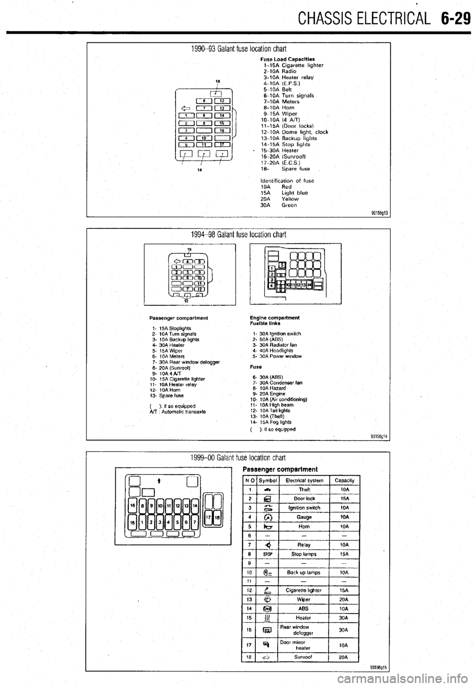
1990-93 Galant fuse location chart Fuse Load Capacities
l-15A Cigarette hghter
Z-10A Radm
3-10A Heater relay
4-10A (E P S.)
5-10A Belt
6-10A Turn signals
7-10A Meters
6-10A Horn
9-15A Wiper
lo-10A (4 A/T)
ll-15A (Door locks)
12-10A Dome hght, clock
13-10A Backup hghts
14-15A Stop hghts
15-30A Heater
16m20A (Sunroof)
17-20A (ECS)
1% spare fuse
ldentlfxation of fuse
10A Red
15A Light blue
20A Yellow
30A Green
93156g13
1994-98 Galant fuse location chart
Passenger compartment
1. 15A StoplIghts
2- 10A Turn signals
3- 1 OA Backup Itghts
4. 30A Heater
5. i5A Wiper
6- IOA Meters
7. 30A Rear wndow defogger
;: fo& fl$oof)
IO- 15A Cagaretle lighler
11. 10A Heater relay
12. IOA Horn
13. Spare fuse
( ): II so equipped
A!T Automallc transaxle Engine compartment
Fusible links
I- 30A Ignition swlch
2. 50A (ABS)
3. 30A Radiator fan
4. 40A Headkghts
5. 30A Power wndow
Fuse
6- 30A (ABS)
7. 30A Condenser fan
6. 10A Hazard
9. 20A Engine
10. 10A (Au conditioning)
11. 10AHigh beam
12. 10ATall lkghts
13. 10A (Theft)
14. i5A Fog lkghls
( ): If so equipped
93156g14
1999-00 Galant fuse location chart
Page 316 of 408
.
SUSPENSION AND STEERING 8-21
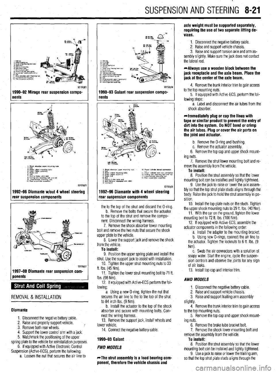
1 nents Q3158!@3 1990-92 Mirage rear suspension compo-
1992-96 Diamante w/out 4 wheel steering
rear suspension components
1 ponents %” 1997-00 Diamante rear suspension corn
REMOVAL & INSTALLATION
Diamante
1. Disconnect the negative battery cable.
2. Raise and properly support vehicle.
3. Remove both rear wheels. !
4. Support the lower control arm with a jack.
5. Matchmark the positioning of the upper
spring plate to the vehicle for reinstallation purposes.
6. If equipped with Active Electronic Control
Suspension (Active-ECS), perform the following:
a. Loosen the nut that secures the air line to
I
93158QM 1990-93 Galant rear suspension compo-
nents
1992-96 Diamante with 4 wheel steering
rear suspension components
the to the top of the strut and discard the O-ring.
b. Remove the bolts that secure the actuator
to the top of the strut and remove the compo-
nent Disconnect the wiring harness.
7. Remove the shock absorber lower mounting
bolt and remove the two nuts that secure the shock
upper plate to the vehicle.
8. Lower the support jack and remove the shock
from the vehicle.
To install:
9. Position the uooer sprina elate and install the
strut. Use the support’jack to as% with installation.
10. Tighten the upper strut mounting nuts to 33
ft. Ibs. (45 Nm).
11. Tighten the lower strut mounting bolt to 71 ft.
Ibs. (98 Nm).
12. If equipped with Active-ECS perform the fol-
lowing:
a. Using a new O-ring, tighten the nut that
secures the air line to the to the top of the strut
to 84 inch Ibs. (9 Nm).
b. Install the actuator to the top of the shock
absorber and secure with mounting bolts. Con-
nect the wiring harness.
13. Remove the support jack, install wheels and
lower vehicle.
14. Connect the negative battery cable.
1990-93 Galant
FWD MODELS
*The strut assembly Is a load bearing com-
ponent, therefore the vehicle chassis and axle weight must be supported separately,
requiring the use of two separate lifting de-
vices.
1. Disconnect the negative battery cable.
2. Raise and support vehicle chassis.
3. Raise and support torsion axle and arm as-
sembly slightly. Make sure the jack does not contact
the lateral rod.
*Always use a wooden block between the
jack receptacle and the axle beam. Place the
jack at the center of the axle beam.
4. Remove the trunk interior trim to gain access
to the top mounting nuts.
5. If equipped with Active-ECS, perform the fol-
lowing steps:
a. Label and disconnect the air tubes from the
shock absorber.
*Immediately plug or cap the lines with
tape or similar product to prevent the entry of
dirt into the system. Do NOT bend or crimp
the air tubes. Plug or cover the air ports on
the joint and actuator.
b. Remove the O-ring and bushing.
c. Remove the actuator assembly.
6. Remove the top cap and upper shock mount-
ing nuts.
7. Remove the strut lower mounting bolt and re-
move the assembly from the vehicle.
To install:
8. Position the strut assembly so that the lower
mounting bolt can be installed and lightly tightened.
9. Use the jack to raise or lower the axle assem-
bly so that the top strut plate studs aligns through the
body. Raise the jack to hold the strut assembly in po-
sition
10. Install the top plate nuts on the studs. Tighten
the upper shock mounting nuts to 29 It. Ibs. (40 Nm).
11. With the car on the ground, tighten the lower
mounting bolt to 72 ft. Ibs. (100 Nm).
12. If equipped with Active-ECS, assemble the
actuator components in the following order:
a. Install the adapter to the mounting bracket.
b. Using new O-rings, connect the air line to
the actuator, Tighten the locknuts to 6 ft Ibs. (9
Nm).
c. Swab the air connectors with a solution of
soapy water. Start the engine, cycle the suspen-
sion controls and observe the joints for any sign
of air leaks.
13. Install top cap and interior trim.
AWD MODELS
1. Disconnect the negative battery cable.
2. Raise and support vehicle chassis.
3. Raise and support trailing arm assembly
slightly.
4. Remove the trunk interior trim to gain access
to the top mounting nuts.
5. Remove the top cap and upper shock mount-
ing nuts.
6. Remove the brake tube bracket bolt.
7. Remove the shock lower mounting bolt and
remove the assembly from the vehicle.
To install:
8. Position the strut assembly so that the lower
mounting bolt can be installed and lightly tightened.
9. Use a jack to raise or lower the trailing arm,
so that the top strut plate studs aligns through the
Page 386 of 408
11-4 TROUBLESHOOTING
Condition
2 Section/Item Number ^i Vehicle has excessive front end dive or locks rear brakes too easily
3-A, 7
Brake pedal goes to floor when pressed and will not pump up
3-A, 8
Brakes make a burning odor
3-A, 9
All Wheel and Four Wheel Drive Vehicles Front wheel or wheel bearing loose
Rear wheel or wheel bearingloose
Front Wheel Drive Vehicles Front wheel or wheel bearing loose
Rear wheel or wheel bearing loose 4-A. 1
4-A: 1
4-A, 1
4-A, 2
Rear Wheel Drive Vehicles Front wheel or wheel bearing loose
Rear wheel or wheel bearing loose 4-A, 2
4-A, 1
Tires worn on inside tread
Tires worn on outside tread
s Tires worn unevenly 4-B, 1
4-B, 2
4-B, 3
Excessive play in steering wheel
Steering wheel shakes at cruising speeds
Steering wheel shakes when braking
Steering wheel becomes stiff when turned 4-c, 1
4-c, 2
3-A, 1
4-c, 4
Vehicle pulls to one side
Vehicle is very bouncy over bumps
Vehicle seems to lean excessively in turns
Vehicle ride quality seems excessively harsh
Vehicle seems low or leans to one side 4-D 1
4-D, 2
4-D, 3
4-D, 4
4-D, 5
Noises Vehicle makes a clicking noise when driven
Vehicle makes a clunking or knocking noise over bumps
Vehicle makes a low pitched rumbling noise when driven
Vehicle makes a squeaking noise over bumps
Vibrations Vehicle vibrates when driven 4-E, 1
4-E, 2
4-E, 3
4-E, 4
4-E, 5
One headlight only works on high or low beam
Headlight does not work on high or low beam
Headlight(s) very dim
Tail light, running light or side marker light inoperative
Tail light, running light or side marker light works intermittently
Tail light, running light or side marker light very dim 5-A, 1
5-A, 2
5-A, 3
/ .
5-B, 1
5-B, 2
5-B, 3
Interior light inoperative
Interior light works intermittently
Interior light very dim 5-c, 1
5-c, 2
5-c, 3