headlight bulb MITSUBISHI DIAMANTE 1900 Repair Manual
[x] Cancel search | Manufacturer: MITSUBISHI, Model Year: 1900, Model line: DIAMANTE, Model: MITSUBISHI DIAMANTE 1900Pages: 408, PDF Size: 71.03 MB
Page 222 of 408
CHASSIS ELECTRICAL 6-19
1. Disconnect the negative battery cable.
are all built into 1 multi-function combination
2. Remove the instrument cluster, as outlined 1. Disconnect the negative battery cable.
earlier in this section. switch that is mounted on the steering col-
2. Using a small screwdriver or other suitable
umn. Refer to Section 8 for procedures re-
3. Remove the retaining screws for the instrument tool, carefully pry the retaining clips from either side
garding the combination switch.
cluster lens and cover assembly. Remove the cover of the switch trim plate.
3.
and lens. Carefully pull the switch and trim plate out of
,
4. Remove the retaining screws for the gauge or the instrument panel.
4. Detach the electrical connectors and remove
warning lamp to be replaced, then remove the gauge
the switch.
or warning lamp.
REMOVAL&INSTALLATION : 5. The installation is the reverse of removal.
To install:
5. Place the gauge or warning lamp into place
and tighten the retaining screws. 1. Disconnect the negative battery cable.
6. Install the instrument cluster lens and cover 2. Using a suitable prytool, disengage the switch
assembly. retaining tabs.
REMOVAL &INSTALLATION 7. Install the instrument cluster. 3. Gently pull the switch from the instrument
8. Connect the negative battery cable. panel.
4. Detach the electrical connector and remove the *On all models the headlights, turn signals,
switch. and on some models, the cruise control func-
5. The installation is the reverse of removal. tion are all built into 1 multi-function combi-
nation switch that is mounted on the steerinq
REMOVAL &INSTALLATION column. Refer to Section 8 for procedures 6
garding the combination switch.
*The headlights, turn signals, dimmer
switch, horn switch, windshield
REMOVAL &INSTALLATION
wiper/washer, intermittent wiper switch and *
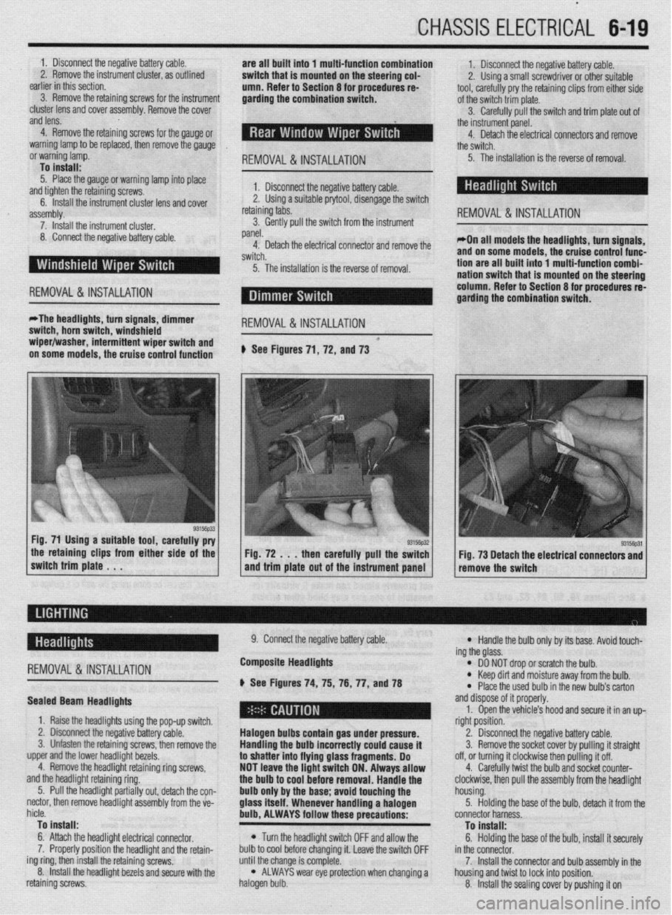
on some models, the cruise control function # See Figures 71, 72, and 73
the retaining clips from either side of the
switch trim plate . . . Fig. 72 . . . then carefully pull the switch
and trim plate out of the instrument panel Fig. 73 Detach the electrical connectors and
remove the switch
-
REMOVAL &INSTALLATION
Sealed Beam Headlights
1. Raise the headlights using the pop-up switch.
2. Disconnect the negative battery cable.
3. Unfasten the retaining screws, then remove the
upper and the lower headlight bezels.
4. Remove the headlight retaining ring screws,
and the headlight retaining ring.
5. Pull the headlight partially out, detach the con-
nectar, then remove headlight assembly from the ve-
hicle.
To install:
6. Attach the headlight electrical connector.
7. Properly position the headlight and the retain-
ing ring, then install the retaining screws.
8. Install the headlight bezels and secure with the
retaining screws. 9. Connect the negative battery cable.
Composite Headlights
6 See Figures 74, 75, 76, 77, anU78
Halogen bulbs contain gas under pressure.
Handling the
bulb incorrectly could cause it
to shatter into flying glass fragments. Do
NOT leave the light switch ON. Always allow
the bulb to cool before removal. Handle the
bulb only by the base; avoid touching the
glass itself. Whenever handling a halogen
bulb, ALWAYS follow these precautions:
l Turn the headlight switch OFF and allow the
bulb to cool before changing it. Leave the switch OFF
until the change is complete.
l ALWAYS wear eye protection when changing a
halogen bulb.
l Handle the bulb only by its base. Avoid touch-
ing the glass.
l DO NOT drop or scratch the bulb. l Keep dirt and moisture away from the bulb.
* Place the used bulb in the new bulb’s carton
and dispose of it properly.
1. Open the vehicle’s hood and secure it in an up-
right position.
2. Disconnect the negative battery cable.
3. Remove the socket cover by pulling it straight
off, or turning it clockwise then pulling it off.
4. Carefully twist the bulb and socket counter-
clockwise, then pull the assembly from the headlight
housing.
5. Holding the base of the bulb, detach it from the
connector harness.
To install:
6. Holding the base of the bulb, install it securely
in the connector.
7. Install the connector and bulb assembly in the
housing and twist to lock into position.
8. Install the sealing cover by pushing it on
Page 223 of 408
.
6-20 CHASSIS ELECTRICAL
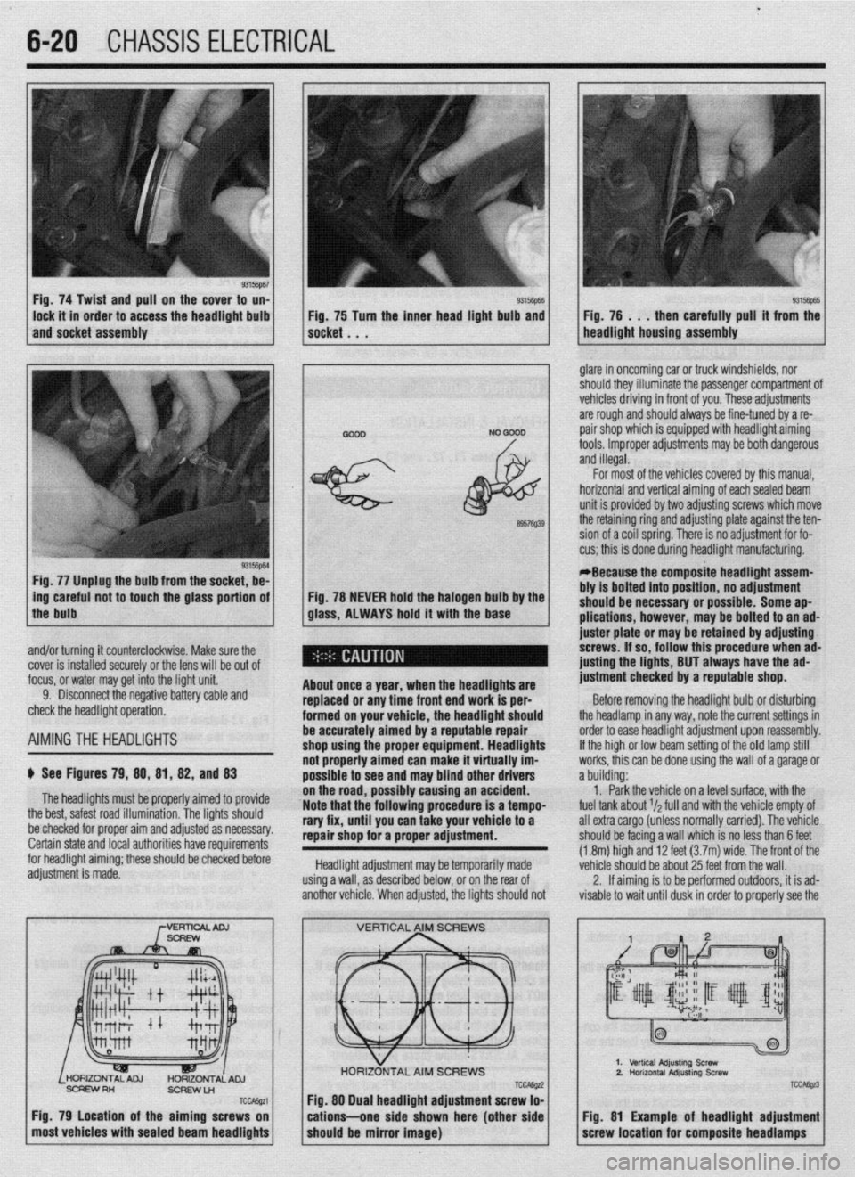
Fig. 74 Twist and pull on the cover to un-
lock it in order to access the headlight bulb
and socket assembly 93Mm Fig, 75 Turn the inner head light bulb and then carefully pull’ it from the
NO 0000 . glare in oncoming car or truck windshields, nor
should they illuminate the passenger compartment of
vehicles driving in front of you. These adjustments
are rough and should always be fine-tuned by a re-
pair shop which is equipped with headlight aiming
tools. Improper adjustments may be both dangerous
and illegal.
Fig. 77 Unplug the bulb from the socket, be-
L
ing careful not to touch the glass portion of
the bulb
I
6957Q39
Fig. 78 NEVER hold the halogen bulb by the
glass, ALWAYS hold it with the base
,
About once a year, when the headllgftts are
replaced or any time front end work is per-
formed on your vehicle, the headlight should
be accurately aimed by a reputable repair
shop uslng the proper equipment. Headlights
not properly aimed can make it virtually im-
possible to see ar Id may blind other drivers
ibly causing an accident.
Note that the’following procedure is a tempo-
rary fix, until you can take your vehicle to a
repair shop for a proper adjustment.
Headlight adjustment may be temporarily made
using a wall, as described below, or on the rear of
another vehicle. When adjusted, the lights should not For most of the vehicles covered by this manual,
horizontal and vertical aiming of eachsealed beam
unit is provided by two adjusting screws which move
the retaining ring and adjusting plate against the ten-
sion of a coil spring. There is no adjustment for fo-
cus; this is done during headlight manufacturing.
*Because the composite headlight assem-
bly is bolted into position, no adjustment
should be necessary or possible. Some ap-
plications, however, may be bolted to an ad-
juster plate or may be retained by adjusting
screws. If so, follow this procedure when ad-
@sting the lights, BUT always have the ad-
justment checked by a reputable shop.
Before removing the headlight bulb or disturbing
the headlamp in any way, note the current settings in
order to ease headlight adjustment upon reassembly.
If the high or low beam setting of the old lamp still
works, this can be done using the wall of a garage or
a building:
1. Park the vehicle on a level surface, with the
fuel tank about r/a full and with the vehicle empty of
all extra cargo (unless normally carried). The vehicle
should be facing a wall which is no less than 6 feet
(1.8m) high and 12 feet (3.7m) wide. The front of the
vehicle should be about 25 feet from the wall.
2. If aiming is to be performed outdoors, it is ad-
visable to wait until dusk in order to properly see the
% and/or turning it counterclockwise. Make sure the
cover is installed securely or the lens will be out of
focus, or water may get into the light unit.
9. Disconnect the negative battery cable and
check the headlight operation.
AIMINGTHE HEADLIGHTS
$ See Figures 79, 88, 81, 82, and 83
The headlights must be proper’ ’ ’ ’
the best, safest road illumination. ’ ’
ly armea IO provrae
The lights should
:.__1__1 __ - -___-_-. on the road, POSSI
be checked for proper aim and adfusreu as IlweSYdly. Certain state and local authorities have requirements
for headlight aiming; these should be checked before
adjustment is made.
SCFEWRH
ScFlEwLn
TCcAssa
Fig. 79 Location of the aiming screws on
most vehicles with sealed beam headlights
TCCAE@ Fig. 88 Dual headlight adjustment screw lo-
cations--one side shown here (other side
should be mirror image)
2.
TCC&z3
Fig. 81 Example of headlight adjustment
screw location for composite headlamps
Page 224 of 408
CHASSIS ELECTRICAL 6-21
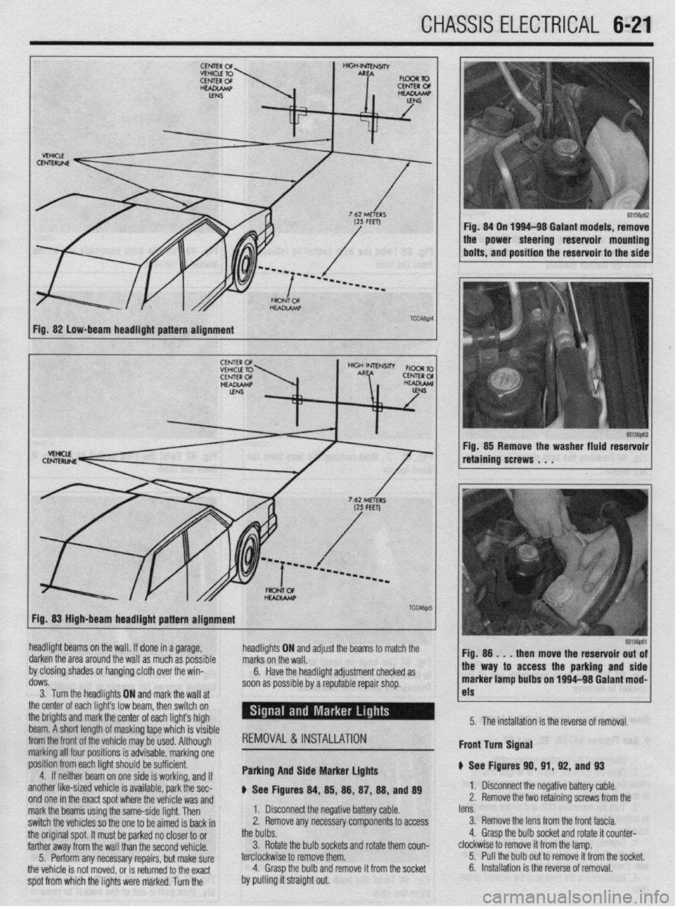
Fig. 82 low-beam headlight pattern alignment
93156pE.3 Fig. 85 Remove the washer fluid reservoir
retaining screws . . .
Fig. 83 High-beam headlight pattern alignment
headlight beams on the wall. If done in a garage,
darken the area around the wall as much as possible
by closing shades or hanging cloth over the win-
dows.
3. Turn the headlights ON and markthe wall at
the center of each light’s low br ram, then switch on
the brights and mark the center of each lights high
beam. A short length of maskin g tape which is visible
from the front of the
whir+ ma . ._..._._ . .._ y be used. Although
marking all four po:
sitions is advisable, marking one
position from each
light should be sufficient.
4. If neithar he; ~. __
Irn on one side is working, and if
another like-sized vehicle is available, park the sec-
nnri nm in the wart cnnt whrw the whirlo um md
headli! jhts ON and adjust the beams to marcn me
I. Disconnect the negative battery cable. marks on the wall.
2. Remove any necessary components to access 6.
the bulbs. Have the headlight adjustment checked as
soon as possible by a reputable repair shop.
3. Rotate the bulb sockets and rotate them coun-
terclockwise to remove them.
4. Grasp the bulb and remove it from the socket REMOVAL&INSTALLATION
Parking And Side Marker Lights
p See Figures 84, 85, 88, 87, 88, and 89 !ss the parking and side
1~ nn loo4-98 Galant mod-
I
1 I-
5315@61
lens. 1 Fio. 8
then move the reservoir out of
3. Remove the lens from the front fascia.
4. Grasp the bulb socket and rotate it counter- marker lamp bult, _.. ._“~-
clockwise to remove it from the lamp.
5. Pull the bulb out to remove it from the socket. 5. The installation is the reverse of removal.
6. Installation is the reverse of removal. Front turn Signal
p See Figures 91
1. Disconnect tl
2. Remove the t 0, 91, 92, and 93
I(? n,-.nn+:.m b.Hnn, nnL.L
z Ill7yau”e “allcly ul”IC. 10 retainino screws from the
spot from which the lights were marked. Turn the . ..I_ WIIY I.8 %,I” V”UVL”fdYI T.II”IU Lll” “VlllUlY ,.UU U,,” mark the beams using the same-side light. Then
switch the vehicles so the one to be aimed is back in
the original spot. It must be parked no closer to or
farther away from the wall than the second vehicle.
5. Perform any necessary repairs, but make sure
the vehicle is not moved, or is returned to the exact
by pulling it straight out.
Page 229 of 408
6-26 CHASSIS ELECTRICAL
Light bulb application chart-199&93 Galant
Light bulb application chart-1994-98 Galant
Description
1 Wattage 1
rrunk lrght Overdrwe rndvzator light
lautomatlc transaxle)
Light bulb application chart-1992-96 Diamante
Light bulb application chart-1997-00 Diamante
Outside
Description
wattage SAE
trade
NO
1 - Headlrght Irnslde)
65W
9005
l----if
2 - HeadlIght loutsldel
55w 9006
3 - Parktng and front
3cP 168
s!de markrr l,ght
4 - Front turn-srgnal light
24cp 1156NA
5 - Hugh-mounted stop
lbght 21cp
921
1 6- Eackuplrght
I 1921 21cp
7 - Stop/tall light
8 - Rear side marker
lkght
9 - License plate light
3cP 168
IO - Rear turn-slgnal lkght
32cp
1156
Description
Wattage
Dome light
Door light
Luggage compartment lrght
Rear personal lrght
Glove compartment lbght
Vanity mrrror lkght
Arr condltfoner control
panel lkght
Cigarette lighter rllumrna-
llcm l1gbt
Outside
7 t License plate Ilght / 3cp
168
6 Stop and tall Irghl 1 32/2cp 1 2057 I
Inside
Light bulb application chart-1999-00 Galant
Light Bulbs -Outside
Descrrptron Wattage
HeadlIght loutsldel 55W
Headlight (Inside1 65W
Front turn-srgnal lkghts 271B\1\1
Fronr srde-marker lrghts
ZCP
Parkrng hghts
3CP
Stop and tarllrghts 3212~~
Rear turn-srgnal lrghts
32cp
Backup lkghts
32~x1
Rear srde-marker lkghts
3CP SAE
Trade No
---
90a
9005
1157NA
199
168
2057
1156
1156
168
LI- 168
Descrrptron Wattage
- . ..-- -- --_ .---
8W
8W
8W
low
5W
5W
14w
14W
t4w
t4w
Ashtray light
Shtft tndrcaror Ilght
fautomatlc Iransaxlel
Exterior
interior
1 - He;;;fghts (inner) - 12V 65W
2- keadlights (outer) 12V 55W
fHB41 6 - Rear tdm-stgnal lights 12V 45cp
7 - Reversrng light - 12V 32cp
6 - Lrcense plate light 12V 3cp
9 - Stop I tall lights 12V 43/3cp
lo- Stop I tall Ibghts 12V 3212~~
11- Hugh mounted stop - 12V 21W
light RoomlIghts 12V 6W
Spot lights 12V RW
Rear personal lrglils - 1% 8W
Door IIghts (clear) 12V 3 4W
Trunk hght - 12V 5W 3 - Parking and front - 12V 3cp
side marker lrght
4 - Fronl turn-slgnal lights 12V 32cp
5 - Front fog llghl 12V 55W (H3)
12- RearsIde-marker light - 12V 3cp
Page 395 of 408
TROUBLESHOOTING 11-13
NOTE: When one shock fails, ft is recommended to replace front or rear
units as pairs.
3. Vehicle leans excessively in turns
a. Check for worn or leaking shock absorbers or strut assemblies and replace as neces-
sary.
b. Check for missing, damaged, or worn stabilizer links or bushings, and replace or in-
stall as necessary.
4. Vehicle ride quality seems excessively ha&h
a. Check for seized shock absorbers or strut assemblies and replace as necessary.
b. Check for excessively high tire pressures and adjust pressures to vehicle recommen-
dations.
5. Vehicle seems low or leans to one side
a. Check for a damaged, broken or weak spring. Replace defective parts and check for a
needed alignment.
b. Check for seized shock absorbers or strut assemblies and replace as necessary.
c. Check for worn or leaking shock absorbers or strut assemblies and replace as neces-
sary.
Noises 1. Vehicle makes a clicking noises when driven
a. Check the noise to see if it varies with road speed. Verify if the noise is present when
coasting or with steering or throttle input. If the clicking noise frequency changes with
road speed and is not affected by steering or throttle input, check the tire treads for a
stone, piece of glass, nail or another hard object imbedded into the tire or tire tread.
Stones rarely cause a tire puncture and are easily removed. Other objects may create
an air leak when removed. Consider having these objects removed immediately at a
facility equipped to repair tire punctures.
b. If the clicking noise varies with throttle input and steering, check for a worn Constant
Velocity (CV-joint) joint, universal (U- joint) or flex joint.
2. Vehicle makes a clunking or knocking noise over bumps
a. A clunking noise over bumps is most often caused by excessive movement or clear-
ance in a suspension component. Check the suspension for soft, cracked, damaged or
worn bushings. Replace the bushings and check the vehicle’s alignment.
b. Check for loose suspension mounting bolts. Check the tightness on subframe bolts,
pivot bolts and suspension mounting bolts, and torque to specification.
c. Check the vehicle for a loose wheel bearing. Some wheel bearings can be adjusted for
looseness, while others must be replaced if loose. Adjust or replace the bearings as
recommended by the manufacturer.
d. Check the door latch adjustment. If the door is slightly loose, or the latch adjustment
is not centered, the door assembly may create noises over bumps and rough surfaces.
Properly adjust the door latches to secure the door. 3. Vehicle makes a low pitched rumbling noise when driven
a. A low pitched rumbling noise is usually caused by a drive train related bearing and is
most often associated with a wheel bearing which has been damaged or worn. The
damage can be caused by excessive brake temperatures or physical contact with a pot
hole or curb. Sometimes the noise will vary when turning. Left hand turns increase the
load on the vehicle’s right side, and right turns load the left side. A failed front wheel
bearing may also cause a slight steering wheel vibration when turning. A bearing
which exhibits noise must be replaced.
b. Check the tire condition and balance. An internally damaged tire may cause failure
symptoms similar to failed suspension parts. For diagnostic purposes, try a known
good set of tires and replace defective tires.
4. Vehicle makes a squeaking noise over bumps
a. Check the vehicle’s ball joints for wear, damaged or leaking boots. Replace a ball joint
if it is loose, the boot is damaged and leaking, or the ball joint is binding. When re-
placing suspension parts, check the vehicle for alignment.
b. Check for seized or deteriorated bushings. Replace bushings that are worn or dam-
aged and check the vehicle for alignment.
c. Check for the presence of sway bar or stabilizer bar bushings which wrap around the
bar. Inspect the condition of the bushings and replace if worn or damaged. Remove
the bushing bracket and apply a thin layer of suspension grease to the area where the
bushings wrap around the bar and reinstall the bushing brackets. ~
5. Vehicle vibrates when driven
a. Check the road surface. Roads which have rough or uneven surfaces may cause un-
usual vi brations.
b. Check the tire condition and balance. An internally damaged tire may cause failure
symptoms similar to failed suspension parts. For diagnostic purposes, try a known
good set of tires and replace defective tires immediately.
c. Check for a worn Constant Velocity (CV-joint) joint, universal (U- joint) or flex joint
and replace if loose, damaged or binding.
d. Check for a loose, bent, or out-of-balance axle or drive shaft. Replace damaged or
failed components.
NOTE: Diagnosing failures related to wheels, tires, steering and the sus-
pension system can often times be accomplished with a careful and thor-
ough test drive. Bearing noises are isolated by noting whether the noises
or symptoms vary when turning left or right, or occur while driving a
straight line. During a teft hand turn, the vehicle’s weight shifts to the
right, placing more force on the right side bearings, such that if a right side
wheel bearing is worn or damaged, the noise or vibration should increase
during light-to-heavy acceleration. Conversely, on right hand turns, the ve-
hicle tends to lean to the left, loading the left side bearings.
Knocking noises in the suspension when the vehicle is driven over rough roads, rail-
road tracks and speed bumps indicate worn suspension components such as bushings,
ball joints or tie rod ends, or a worn steering system.
1. One headlight only works on high or low beam
a. Check for battery voltage at headlight electrical connector. If battery voltage is present,
replace the headlight assembly or bulb if available separately. If battery voltage is not
present, refer to the headlight wiring diagram to troubleshoot.
2. Headlight does not work on high or low beam
a. Check for battery voltage and ground at headlight electrical connector. If battery volt-
age is present, check the headlight connector ground terminal for a proper ground. If
battery voltage and ground are present at the headlight connector, replace the head-
light assembly or bulb if available separately. If battery voltage or ground is not pre-
sent, refer to the headlight wiring diagram to troubleshoot.
b. Check the headlight switch operation. Replace the switch if the switch is defective or
ooerates intermittentlv. 1. Tail light, running light or side marker light inoperative
a. Check for battery voltage and ground at light’s electrical connector. If battery voltage is
present, check the bulb socket and electrical connector ground terminal for a proper
ground. If battery voltage and ground are present at the light connector, but not in the
socket, clean the socket and the ground terminal connector. If battery voltage and
ground are present in the bulb socket, replace the bulb. If battery voltage or ground is
not present, refer to the wiring diagram to troubleshoot for an open circuit.
b. Check the light switch operation and replace if necessary.
2. Tall light, running light or side marker light works intermittently
a. Check the bulb for a damaged filament, and replace if damaged.
b. Check the bulb and bulb socket for corrosion, and clean or replace the bulb and
socket.
w 3. Headlight(s) very dim
a. Check for battery voltage and ground at headlight electrical connector. If battery volt-
age is present, trace the ground circuit for the headlamp electrical connector, then
clean and repair as necessary. If the voltage at the headlight electrical connector is
significantly less than the voltage at the battery, refer to the headlight wiring diagram
to troubleshoot and locate the voltage drop. c. Check for loose, damaged or corroded wires and electrical terminals, and repair as
necessary.
d. Check the light switch operation and replace if necessary.
3. Tail light, running light or side marker light very dim
a. Check the bulb and bulb socket for corrosion and clean or replace the bulb and
socket.