fuel type MITSUBISHI DIAMANTE 1900 Repair Manual
[x] Cancel search | Manufacturer: MITSUBISHI, Model Year: 1900, Model line: DIAMANTE, Model: MITSUBISHI DIAMANTE 1900Pages: 408, PDF Size: 71.03 MB
Page 8 of 408
GENERALINFORMATIONAND MAINTENANCE l-9
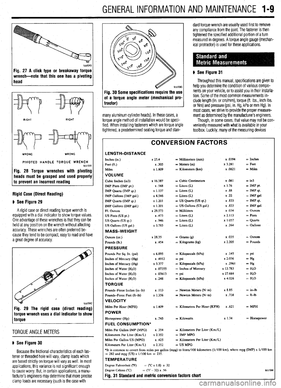
Fig. 27 A click type or breakaway torque
wrench-note that this one has a pivoting
head
v
WRONG WRONG
PIVOTED HANDLE TOR(IUE WRENCH tccS1041 Fig. 28 Torque wrenches with pivoting
heads must be grasped and used properly
to prevent an incorrect reading
Rigid Case (Direct Reading)
# See Figure 29
A rigid case or direct reading torque wrench is
equipped with a dial indicator to show torque values.
One advantage of these wrenches is that they can be
held at any position on the wrench without affecting
accuracy. These wrenches are often preferred be-
cause they tend to be compact, easy to read and have
a great degree of accuracy.
lccs1042 Fig. 29 The rigid case (direct reading)
torque wrench uses a dial indicator to show
torque
TORQUEANGLEMETERS
# See Figure 30
Because the frictional characteristics of each fas-
tener or threaded hole will vary, clamp loads which
are based strictly on torque will vary as well. In most
applications, this variance IS not significant enough
to cause worry. But, in certain applications, a manu-
facturers engineers may determine that more precise
clamp loads are necessary (such is the case with :ig. 30 Some specifications require the use
rf a torque angle meter (mechanical pro.
ractor)
many aluminum cylinder heads). In these cases, a
torque angle method of installation would be speci-
fied. When installing fasteners which are torque angle
tightened, a predetermined seating torque and stan- dard torque wrench are usually used first to remove
any compliance from the joint. The fastener is then
tightened the specified additional portion of a turn
measured in degrees. A torque angle gauge (mechan-
ical protractor) is used for these applications.
) See Figure 31
Throughout this manual, specifications are given to
help you determine the condition of various compo-
nents on your vehicle, or to assist you in their installa-
tion. Some of the most common measurements in-
clude length (in. or cm/mm), torque (ft. Ibs., inch Ibs.
or Nm) and pressure (psi, in. Hg, kPa or mm Hg). In
most cases, we strive to provide the proper measure-
ment as determined by the manufacturers engineers.
Though, in some cases, that value may not be con-
veniently measured with what is available in your
toolbox. Luckily, many of the measuring devices
CONVERSION FACTORS
LENGTH-DISTANCE Inches (I”.) x 25.4 = Millimeters (mm) x .0394 = Inches
Feet (ft.) x ,305
= Meters (m) x 3.281 = Feet
Miles x 1.609 = Kilometers (km) x .0621
= Miles
VOLUME Cubic Inches (in3) x 16.387 = Cubic Centimeters x .061 = in3
IMP Pints (IMP pt.) x .568 = Liters (L) x 1.76
= IMP pt.
IMP Quarts (IMP qt.) x 1.137 = Liters (L) x .88 = IMP qt.
IMP Gallons (IMP gal.) x 4.546 = Liters (L) 7, .22
= IMP gal.
IMP Quarts (IMP qt ) x 1.201 = US Quarts (US qt.) x ,833 = IMP qt.
IMP Gallons (IMP gal.) x 1.201
= US Gallons (US gal.) x ,833
= IMP gal.
Fl. Ounces x 29.573 = Millihters x 034
= Ounces
us Pints (Us pt.) x ,473 = Liters (L) x 2.113 = Pints
US Quarts (US qt.) x .946 = Liters (L) x 1.057
= Quarts
US Gallons (US gal.) x 3.785 = Liters (L) x ,264 = Gallons
MASS-WEIGHT
Ounces (oz.) x 28.35
= Grams (g) x ,035
= Ounces
Pounds (lb ) x ,454 = Kdograms (kg) x 2.205
= Pounds
PRESSURE ’ Pounds Per Sq. In. (psi) x 6.895 = Kilopascals (kPa) x ,145 = psi
Inches of Mercury (Hg) x .4912
= psi x 2.036 = Hg
Inches of Mercury (Hg) x 3.377 = Kilopascals (kPa) x .2961
= Hg
Inches of Water (H,O)
x .07355 = Inches of Mercury x 13 783 = H,O
Inches of Water (H,O) x .03613 = psi x 27.684
= Hz0
Inches of Water (H,O) x ,248
= Kilopascals (kPa) x4026
= H,O
TORQUE Pounds-Force Inches (in-lb)
x ,113 = Newton Meters (N.m) x 8.85 = in-lb
Pounds-Force Feet (ft-lb)
x 1.356 = Newton Meters (N*m) x ,738 = ft-lb
VELOCITY Miles Per Hour (MPH)
x 1.609 = Kilometers Per Hour (KPH) x .621 = MPH POWER Horsepower (Hp) x ,745 = Kdowatts x 1.34
= Horsepower FUEL CONSUMPTION’ Mdes Per Gallon IMP (MPG) x .354
= Kilometers Per Liter (Km/L)
Kilometers Per Liter (Km/L)
x 2.352 = IMP MPG
Miles Per Gallon US (MPG) x ,425
= Kilometers Per Liter (Km/L)
Kdometers Per Liter (Km/L) x 2.352
= US MPG
*It 1s common to covert from miles per gallon (mpg) to hters/lOO kilometers (l/100 km), where mpg (IMP) x l/ID0 km
= 282 and mpg (US) x l/lo0 km = 235.
TEMPERATURE Degree Fahrenheit CF) = (“C x 1.8) + 32
Degree Celsms (‘C)
= CF - 32) x 56
tccsio4d
Fig. 31 Standard and metric conversion factors chart
Page 9 of 408
.
l-10 GENERALINFORMATIONAND MAINTENANCE
which are available today will have two scales so the
The conversion factor chart is used by taking the
Standard or Metric measurements may easily be given specification and multiplying it by the neces-
taken. If any of the various measuring tools which are sary conversion factor. For instance, looking at the
available to you do not contain the same scale as first line, if you have a measurement in inches such
listed in the specifications, use the accompanying
as “free-play should be 2 in.” but your ruler reads
conversion factors to determine the proper value. only in millimeters, multiply 2 in. by the conversion factor of 25.4 to get the metric equivalent of 50.8mm.
Likewise, if the specification was given only in a Met-
ric measurement, for example in Newton Meters
(Nm), then look at the center column first. If the mea-
surement is 100 Nm, multiply it by the conversion
factor of 0.738 to get 73.8 ft. Ibs.
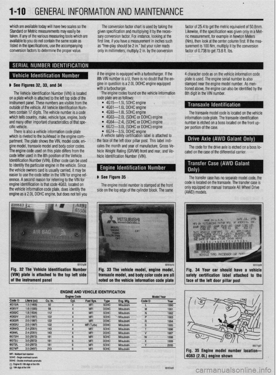
b See Figures 32,33, and 34
The Vehicle Identification Number (VIN) is located
on a plate which is attached to the left top side of the
instrument panel. These numbers are visible from the
outside of the vehicle. All Vehicle Identification Num-
bers contain 17 digits. The vehicle number is a code
which tells country, make, vehicle type, engine, body
and many other important characteristics of that spe-
cific vehicle.
There is also a vehicle information code plate
which is riveted to the bulkhead in the engine com-
partment. The plate shows the VIN, model code, en-
gine model, transaxle model and body color codes.
The engine code used on this plate differs from the
code letter used in the 8th position of the Vehicle
Identification Number (VIN). Either code can be used
to identify the particular engine in the vehicle. Since
the vehicle owners card is usually carried, it may be if the engine is equipped with a turbocharger. If the
8th VIN number is a U, there is no doubt that the en-
gine in question is a 2.OL DOHC engine equipped
with a turbocharger.
The engine codes found on the vehicle information
code plate are as follows:
l 4G15--1.5L SOHC engine l 4G61-1.6L DOHC engine l 4G93-1.8L SOHC engine l 4G63-2.OL (SOHC or DOHC) engine l 4G64-2.4L (SOHC or DOHC) engine l 6G72-3.OL (SOHC or DOHC) engine l 6G74-3.5L DOHC engine
A vehicle safety certification label is attached to
the face of the left door pillar post. This label indi-
cates the month and year of manufacture, Gross Ve-
hicle Weight Rating (GRVW) front and rear, and Ve-
hicle Identification Number (VIM). 4 character code as on the vehicle information code
plate is used. The engine serial number is also
stamped near the engine model number. As men-
tioned above, the engine can also be identified by the
8th digit in the VIN number.
The transaxle model code is located on the vehicle
information code plate. The transaxle identification
number is etched on a boss located on the front up-
per portion of the case.
The code for the drive axle is etched on a boss lo-
cated on the case of the differential carrier.
easier to use the code letter in the VIN for engine ref-
erence. A second reason for referring to the VIN for
engine identification is that code 4663, located on
the vehicle information code plate, does identify the
engine as a 2.OL DOHC engine, but does not tell you ) See Figure 35
The engine model number is stamped at the front
side on the top edge of the cylinder block. The same
Fig. 32 The Vehicle Identification Number
g3’51p’o of the instrument panel _I:^1 / Fig. 33 The vehicle model, engine model,
(VIN) plate is attached to the top left side
bansaxle model, and body color code are all
noted on the vehicle information code plate
ENGINE AND VEHiCLE IDENTlFlCATlON
EnglnCode
ModelYerr
todeal
LIten (cc)
Cu. In. W. Fuel+ Type m.hWg. Code@ Year ,G15JA 1.5 (1468) 92 4 MFI SOHC Mitsubishi
L 1990
IG61N 1.6(15QQ) 98 4 MFI DOHC
Mitsubishi M 1991
1G93lC 1.8 (1834) 112 4 MFI SOHC Mitsubishi N 1992
IG63N 2.0 (1997) 122 4 MFI SOHC “-Mitsubishi P
1993
!G63Fi 2.0 (1997) 122 4 MFI DOHC Mitsubishi
R 1994
,G63iU 2.0 (1997) 122 4 MFI-Tuibo DOHC Mitsubishi
S 1995
.GMffi 2.4 (2351) 143 4 MFI SOHC
Mitsubishi T 1996
iG64L 2.4 (2351) 143 4 MFI DOHC Mitsubishi V
lEzH 3.0 1997
(2972) 161 6 MFI SOHC Mitsubishi W 1998
;G7ZJ 3.0 (2Q72) 161 6 MFI GQHC Mitsubishi
~.. X 1999
iG7zL 3.0 (2972) 181
~ 6 MFI SOHC ___-___ Miisubishi
Y 2000
iG74lP 3.5 (3497) 213 6 MFI SOHC Miisubishi
The transfer case has no separate model code, the
code is located on the transaxle. The transfer case is
onlv eoUiODed on manual transaxle All Wheel Drive
(AWD)‘mbdels.
Fig. 34 Your car should have a vehicle
Fig. 35 Engine model number location-
4663 (2.OL) engine shown
Page 21 of 408
l-22 GENERALINFORMATIONAND MAINTENANCE
tears. If the boot is damaged, it should be replaced
trode is to the block’s cooling passages) the cooler it
your driving is long distance, high speed travel, use a
immediately. Please refer to Section 7 for procedures.
will operate. A plug that absorbs little heat and re-
colder plug; if most of your driving is stop and go,
mains too cool will quickly accumulate deposits of
use a hotter plug. Original equipment plugs are gen-
oil and carbon since it is not hot enough to burn
erally a good compromise between the 2 styles and
them off. This leads to plug fouling and consequently
most people never have the need to change their
to misfiring. A plug that absorbs too much heat will
plugs from the factory-recommended heat range.
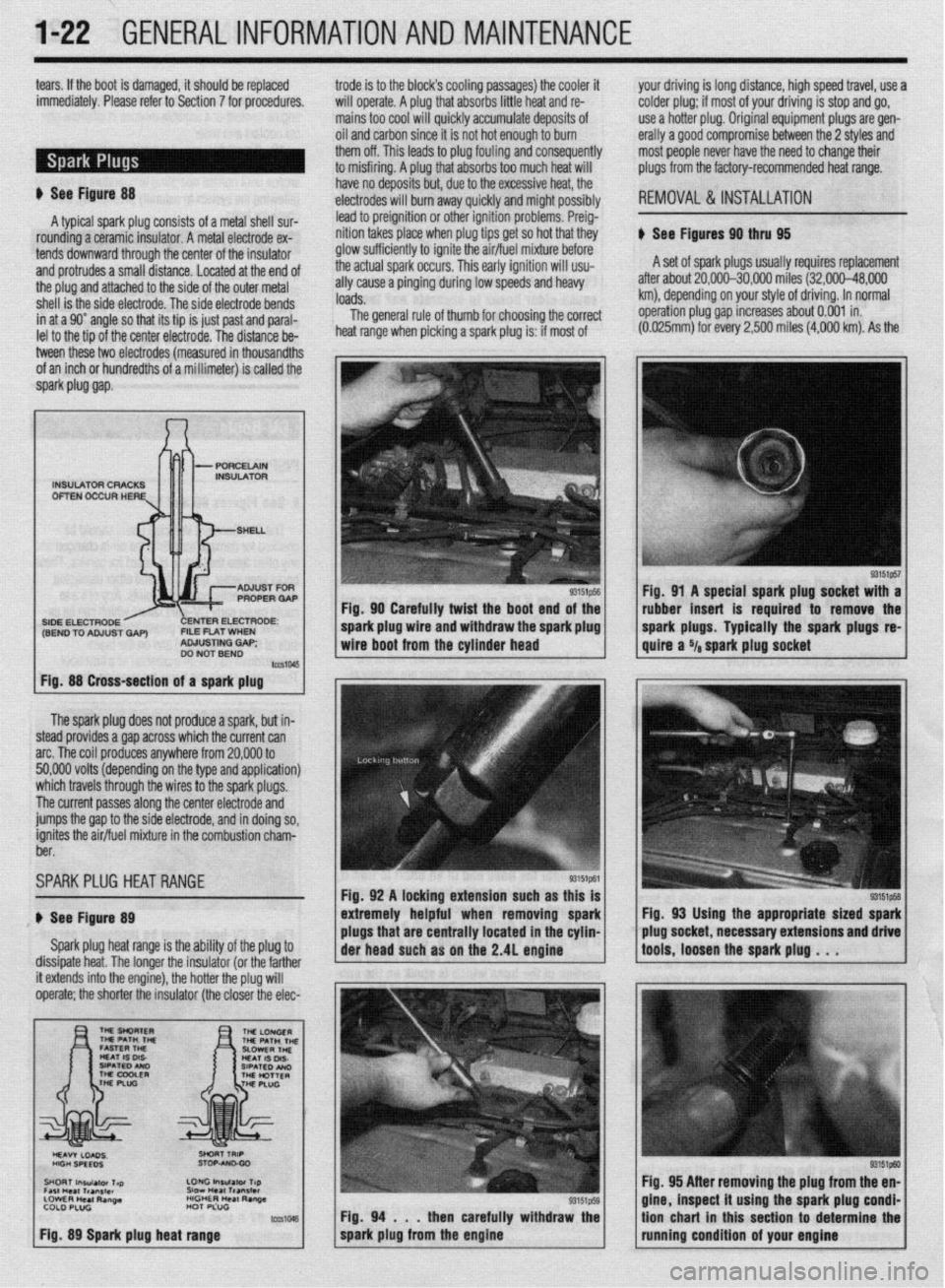
ti See Figure 88 have no deposits but, due to the excessive heat, the
,electrodes will burn away quickly and might possibly
REMOVAL &INSTALLATION
A typical spark plug consists of a metal shell sur- lead to preignition or other ignition problems. Preig-
rounding a ceramic insulator. A metal electrode ex- nition takes place when plug tips get so hot that they
ti See Figures 90 thru 95
tends downward through the center of the insulator glow sufficiently to ignite the air/fuel mixture before
and protrudes a small distance. Located at the end of the actual spark occurs. This early ignition will usu- A set of spark plugs usually requires replacement
the plug and attached to the side of the outer metal ally cause a pinging during low speeds and heavy after about 20,000-30,000 miles (32,000-48,000
shell is the side electrode. The side electrode bends loads. km), depending on your style of driving. In normal
in at a 90” angle so that its tip is just past and paral- The general rule of thumb for choosing the correct operation plug gap increases about 0.001 in.
lel to the tio of the center electrode. The distance be- heat range when picking a spark plug is: if most of (0.025mrn) for every 2,500 miles
(4,000 km). As the
tween these two electrodes (measured in thousandths
of an inch or hundredths of a millimeter) is called the
spark piug gap.
The spark plug does not produce a spark, but in-
steed provides a gap across which the current can
arc. The coil produces anywhere from 20,000 to
50,000 volts (depending on the type and application)
which travels through the wires to the spark plugs.
The current passes along the center electrode and
jumps the gap to the side electrode, and in doing so,
ignites the air/fuel mixture in the combustion charn-
ber.
SPARKPLUG HEATRANGE
ti See Figure 89
Spark plug heat range is the ability of the plug to
dissipate heat. The longer the insulator (or the farther
INSULATOR CRACKS
OFTEN OCCUR HERE
SIDE ELECTRODE ENTER ELECTRODE:
(SEND TO ADJUST GAP) FILE FLAT WHEN
ADJUSTING GAP;
DO NOT BEND
Fig. 88 Cross-section of a spark plug
it extends into the engine), the hotter the plug will
operate; the shorter the insulator (the closer the elec- Fig. 90 Carefully twist the boot end of the
I
spark plug wire and withdraw the spark plug
wire boot from the cylinder head
Fig. 92 A locking extension such as this is
extremely helpful when removing spark
plugs that are centrally located in the cyhn-
Fig. 94 . . .
then carefully withdraw the
spark plug from the engine Fig. 91 A special spark plug socket with a
rubber insert is required to remove the
spark plugs. Typically the spark plugs
re-
quire a Ya spark plug socket
Fig, 93 Using the appropriate sized spark
plug socket, necessary extensions and drive
tools, loosen the spark plug . . .
93151ptxl Fig. 95 After removing the plug from the en-
gine, inspect it using the spark plug condi-
tion chart in this section to determine the
running condition of your engine
Page 22 of 408
t
GENERALINFORMATIONAND MAINTENANCE l-23
gap increases, the plug’s voltage requirement also in-
creases. It requires a greater voltage to jump the the spark plug counterclockwise to loosen and re-
move the spark plug from the bore.
wider gap and about &o to three times as much volt-
age to fire the plug at high speeds than at idle. The
improved air/fuel ratio control of modern fuel injec-
tion combined with the higher voltage output of mod- Be sure not to use a flexible extension on the place. The click may be felt or heard, then gently pull
ern ignition systems will often allow an engine to run socket. Use of a flexible extension may allow back on the boot to assure proper contact.
.___. . _
significantly longer on a set of standard spark plugs, a shear force to be agptf’ ea to me plug.
A 12. On the 3.OL fSOHC and DOHC) and 3.5L en-
LL_ _I___ -u I_ IL-
but keep in mind that efficiency will drop as the gap shear force could break tne pug on III me
tion 3 for the installation procedure.
widens (along with fuel economy and power). cylinder head, leading to costly and frustrat-
13. If equipped, install the center cover.
When you’re removing spark plugs, work on one ing repairs.
at a time. Don’t start by removing the plug wires all at
once, because, unless you number them, they may To install:
INSPECTION & GAPPING
11. Apply a small amount of silicone dielectric
compound to the end of the spark plug lead or inside
the spark plug boot to prevent sticking, then install
the boot to the spark plug and push until it clicks into
gines, install the upper intake manifold. Refer to Sec-
,,Y” ..1111 uy”’ 1 the neaative bat&v cable and if become mixed up. Take a minute before you begin
and number the wrrpc with +sne
1. Disconnect. ~~.~
--..-., -..-.-, -..-
thevehicle has been run recently, allow the engine to
thoroughly cool.
2. If equipped, remove the center cover.
3. On the 3.OL (SOHC and DOHC) and 3.5L en-
gines, the upper intake manifold must be removed to
access the rear spark plugs. Refer to Section 3 for the
removal procedure.
4. Carefully twist the spark plug wire boot to
loosen it, then pull upward and remove the boot from
the plug. Be sure to pull on the boot and not on the
wire, otherwise the connector located inside the boot
may become separated.
5. Using compressed air, blow any water or de-
bris from the spark plug well to assure that no harm-
ful contaminants are allowed to enter the combustion
chamber when the spark plug is removed. If com-
pressed air is not available, use a raa or a brush to must be replaced.
Check the plugs for deposits and wear, If they are 7. Inspect the spark plug boot for tears or dam-
age. If.a damaged boot is found, the spark plug wire
8. Using a wire feelergauge, check and adjust
the spark plug gap. When using a gauge, the proper
size should pass between the electrodes with a slight
drag. The next larger size should not be able to pass
while the next smaller size should pass freely.
9. Carefully thread the plug into the bore by
hand. If resistance is felt before the plug is almost
completely threaded, back the plug out and begin
threading again. In small, hard to reach areas, an old
spark plug wire and boot could be used as a thread-
ing tool. The boot will hold the plug while you twist
the end of the wire and the wire is supple enough to
twist before it would allow the plug to crossthread.
Do not use the spark plug sock?
l -- K-rrA tha nhme Alwmm rarntdlv thw GL I” IlllGa”
the possibility of crossthreading and damag- lad the plug
. ..Y f..“YY. rn”Y,‘““mY*“.‘, .I**” by hand or using an old plug wire to prevent
ing the cylinder head bore.
10. Carefully tighten the spark plug. If the plug
you are installing is equipped with a crush washer,
seat the plug, then tighten about I/, turn to crush the
washer. If you are installing a tapered seat plug,
tighten the plug to specifications provided by the ve-
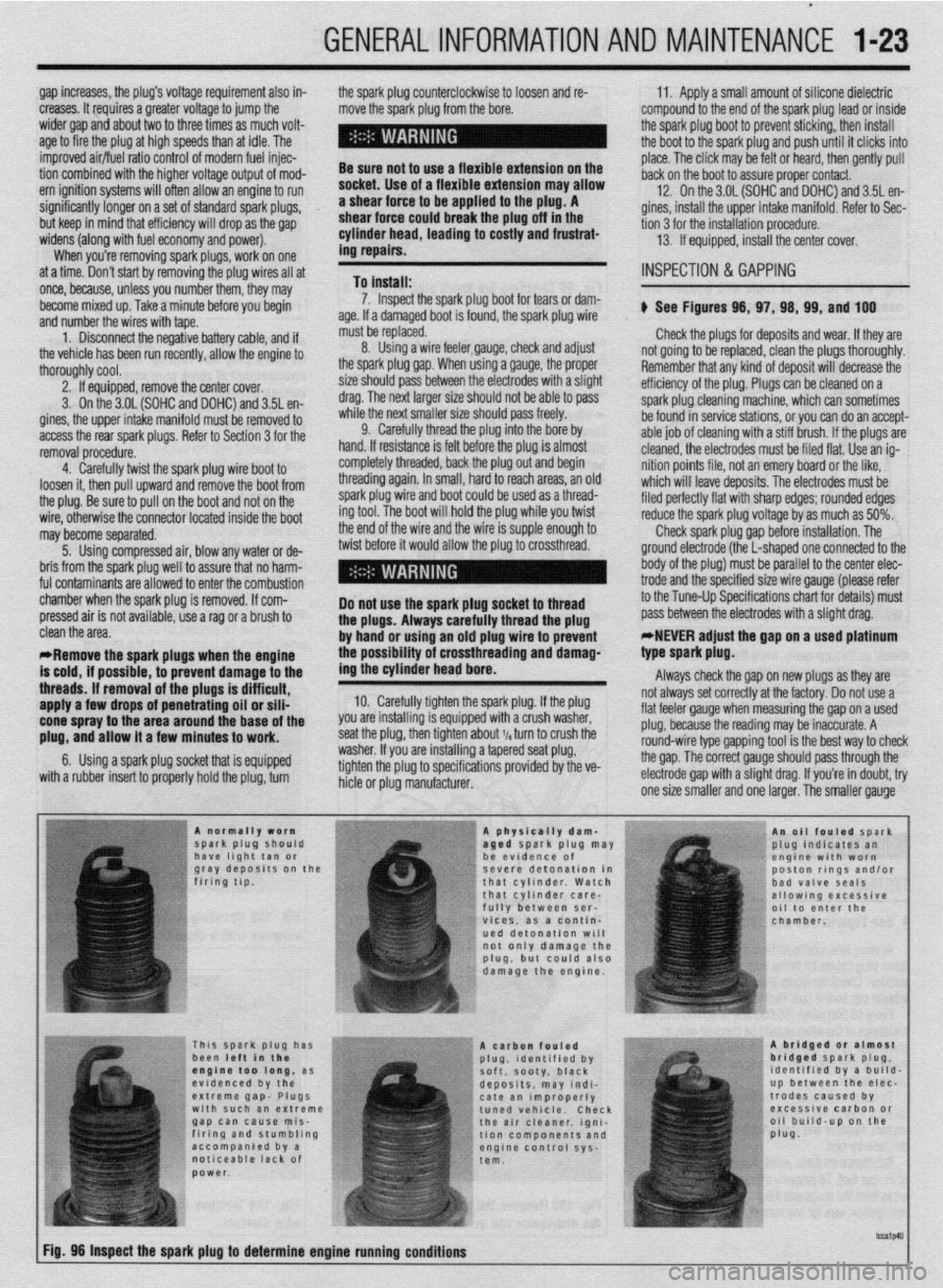
hicle or plug manufacturer. b See Figures 98, 97, 98, 99, and 100
not going to be replaced, clean the plugs thoroughly.
Remember that any kind of deposit will decrease the
efficiency of the plug. Plugs can be cleaned on a
spark plug cleaning machine, which can sometimes
be found in service stations, or you can do an accept-
able job of cleaning with a stiff brush. If the plugs are’
cleaned, the electrodes must be filed flat. Use an ig-
nition points file, not an emery board or the like,
which will leave deposits. The electrodes must be
filed perfectly flat with sharp edges; rounded edges
reduce the spark plug voltage by as much as 50%.
Check spark plug gap before installation. The
ground electrode (the L-shaped one connected to the
body of the plug) must be parallel to the center elec-
trode and the specified size wire gauge (please refer
to the Tune-Up Specifications chart for details) must
pass between the electrodes with a slight drag:
*,NEVER adjust the gap on a used platinum
. clean the area.
*Remove the spark plugs when the engine
is cold, if possible, to prevent damage to the
threads. If removal of the plugs is difficult,
apply a few drops of penetrating oil or sili-
cone spray to the area around the base of the
plug, and allow it a few minutes to work.
6. Using a spark plug socket that is equipped
with a rubber insert to properly hold the plug, turn type spark plug.
Always check the gap on new plugs as they are
not always set correctly at the factory. Do not use a
flat feeler gauge when measuring the gap on a used
plug, because the reading may be inaccurate. A
round-wire type gapping tool is the best way to check
the gap. The correct gauge should pass through the
electrode gap with a slight drag. If you’re in doubt, try
one size smaller and one laraer. The smaller aauqe
Page 31 of 408
.
1-32 GENERALINFORMATIONAND MAINTENANCE
CONDITION
EFFECT
CAUSE
CORRECTION UNDER-INFLATION
EXCESSIVE SPEED’ WORN OR OUT-
OF-ALIGNMENT
ADJUST PRESSURE TO
SPECIFICATIONS WHEN
TIRES ARE COOL
ROTATE TIRES
/ BALANCE WHEELS INSPECT SUSPENSION
HAVE TIRE INSPECTED FOR FURTHER USE.
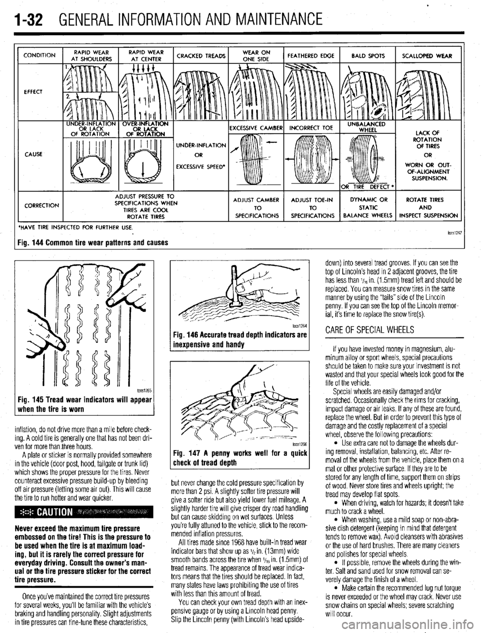
lCCSi267 ig. 144 Common tire wear patterns and causes
1~~~1265 Fig. 145 Tread wear indicators will appear
when the tire is worn
inflation, do not drive more than a mile before check-
ing. A cold tire is generally one that has not been dri-
ven for more than three hours.
A plate or sticker is normally provided somewhere
in the vehicle (door post, hood, tailgate or trunk lid)
which shows the proper pressure for the tires. Never
counteract excessive pressure build-up by bleeding
off air pressure (letting some air out). This will cause
the tire to run hotter and wear quicker.
Never exceed the maximum tire pressure
embossed on the tire! This is the pressure to
be used when the tire is at maximum load-
ing, but it is rarely the correct pressure for
everyday driving. Consult the owner’s man-
ual or the tire pressure sticker for the correct
tire pressure.
Once you’ve maintained the correct tire pressures
for several weeks, you’ll be familiar with the vehicle’s
braking and handling personality. Slight adjustments
in tire pressures can fine-tune these characteristics,
1~~~1264 Fig. 146 Accurate tread depth indicators are
inexuensive and handv
Fig. 147 A penny works well for a quick
check of tread death
but never change the cold pressure specification by
more than 2 psi. A slightly softer tire pressure will
give a softer ride but also yield lower fuel mileage. A
slightly harder tire will give crisper dry road handling
but can cause skidding on wet surfaces. Unless
you’re fully attuned to the vehicle, stick to the recom-
mended inflation pressures.
All tires made since 1968 have built-in tread wear
indicator bars that show up as j/2 in. (13mm) wide
smooth bands across the bre when V,~ in. (1.5mm) of
tread remains. The appearance of tread wear indica-
tors means that the tires should be replaced. In fact,
many states have laws prohibiting the use of tires
with less than this amount of tread.
You can check your own tread depth with an inex-
pensive gauge or by using a Lincoln head penny.
Shp the Lrncoln penny (with Lincoln’s head upside- down) into several tread grooves. If you can see the
top of Lincoln’s head in 2 adjacent grooves, the tire
has less than V,~ in. (1.5mm) tread left and should be
replaced. You can measure snow tires in the same
manner by using the “tails” side of the Lincoln
penny. If you can see the top of the Lincoln memor-
ial, its time to replace the snow tire(s).
CAREOFSPECIALWHEELS
If you have invested money in magnesium, alu-
minum alloy or sport wheels, special precautions
should be taken to make sure your investment is not
wasted and that your special wheels look good for the
life of the vehicle.
Special wheels are easily damaged and/or
scratched. Occasionally check the rims for cracking,
impact damage or air leaks. If any of these are found,
replace the wheel. But in order to prevent this type of
damage and the costly replacement of a special
wheel, observe the following precautions:
l Use extra care not to damage the wheels dur-
ing removal, installation, balancing, etc. After re-
moval of the wheels from the vehicle, place them on a
mat or other protective surface. If they are to be
stored for any length of time, support them on strips
of wood. Never store tires and wheels upright; the
tread may develop flat spots.
l When driving, watch for hazards; it doesn’t take
much to crack a wheel.
l When washing, use a mild soap or non-abra-
sive dish detergent (keeping in mind that detergent
tends to remove wax). Avoid cleansers with abrasives
or the use of hard brushes. There are many cleaners
and polishes for special wheels.
l If possrble, remove the wheels during the win-
ter. Salt and sand used for snow removal can se-
verely damage the finish of a wheel.
l Make certain the recommended lug nut torque
is never exceeded or the wheel may crack. Never use
snow chains on special wheels; severe scratching
will occur.
Page 32 of 408
GENERALINFORMATIONAND MAINTENANC-E 1133
Used fluids such as engine oil, transaxle fluid, an-
tifreeze and brake fluid are hazardous wastes and
must be disposed of properly. Before draining any
fluids, consult with your local authorities; in many ar-
eas, waste oil, antifreeze, etc. is being accepted as a
part of recycling programs. A number of service sta-
tions and auto parts stores are also accepting waste
fluids for recycling.
Be sure of the recycling center’s policies before
draining any fluids, as many will not accept different
fluids that have been mixed together.
ENGINE OIL
6 See Figure 148
WMitsubishi recommends that SAE 5W-30
viscosity engine oil should be used for all clia
mate conditions, however, SAE low-30 is ac
ceptable for vehicles operated in moderate-
to-hot climates. the SAE number, the lighter the oil; the lower the vis-
cosity, the easier it is to crank the engine in cold
weather but the less the oil will lubricate and protect
the engine in high temperatures. This number is
marked on every oil container.
Oil viscosity’s should be chosen from those oils
recommended for the lowest anticipated temperatures
during the oil change interval. Due to the need for an
oil that embodies both good lubrication at high tem-
peratures and easy cranking in cold weather, multi-
grade oils have been developed. Basically, a multi-
grade oil is thinner at low temperatures and thicker at
high temperatures. For example, a low-40 oil (the W
stands for winter) exhibits the characteristics of a 10
weight (SAE 10) oil when the car is first started and
the oil is cold. Its lighter weight allows it to travel to
the lubricating surfaces quicker and offer less resis-
tance to starter motor cranking than, say, a straight
30 weight (SAE 30) oil. But atier the ensine reaches
operating temperature, the low-40 oil begins acting
like straight 40 weight (SAE 40) oil, its heavier weight
providing greater lubrication with less chance of
foaming than a straight 30 weight oil. Synthetic oil is not for every car and every type of
driving, so you should consider your engine’s condi-
tion and your type of driving. Also, check your car’s
warranty conditions regarding the use of synthetic oils.
FUEL
All models equipped with a SOHC (Single Over-
head Camshaft) engine are designed to operate using
regular unleaded fuel with a minimum of 87 octane.
All models equipped with a DOHC (Dual Overhead
Camshaft) engine are designed to operate using reg-
ular unleaded fuel with a minimum of 91 octane. Mit-
subishi warns that using gasoline with a lower octane
rating can cause persistent and heavy knocking, and
may cause internal engine damage.
If your vehicle is having problems with rough idle
or hesitation when the enoine is cold, it mav be
caused by low volatility fuel. If this occurs, iry a dif-
ferent grade or brand of fuel.
'OPERATION 1~ FOREIGN COUNTRIES
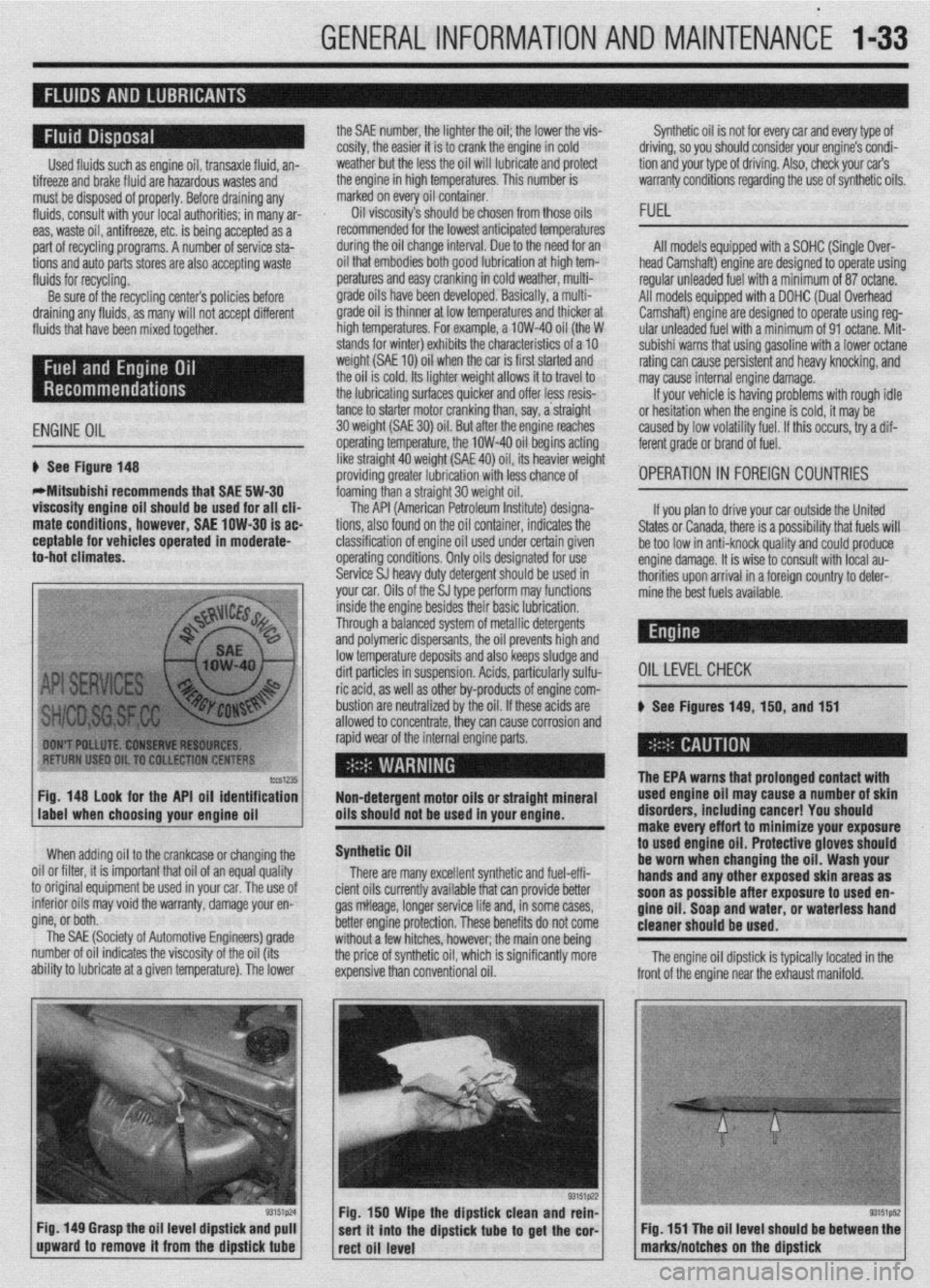
lccS1235 Fig. 148 look for the API oil identification
Non-detergent motor oils or straight mineral
label when choosing your enaine oil oils should not be used in your engine.
When adding oil to the crankcase or changing the
0 Nil or filter, it is important that oil of an equal quality
I original equipment be used in your car. The use of
. tc mtenor 011s may void the warranty, damage your en-
gine, or both. __
The SAE (Society of Automotive Engineers) grade
number of oil indicates the viscosity of the oil (its
ability to lubricate at a given temperature). The lower
Fig. 149 Grasp the oil level dipstick and pull
upward to remove it from the dipstick
tube
The API (American Petroleum Institute) designa-
tions, also found on the oil container, indicates the
classification of engine oil used under certain given
operating conditions. Only oils designated for use
Service SJ heavy duty detergent should be used in
your car. Oils of the SJ type perform may functions If you plan to drive your car outside the United
States or Canada, there is a possibility that fuels will
be too low in anti-knock quality and could produce
engine damage. It is wise to consult with local au-
thorities upon arrival in a foreign country to deter-
mine the best fuels available.
inside the engine besides their basic lubrication.
Through a balanced system of metallic detergents
and polymeric dispersants, the oil prevents high and
low temperature deposits and also keeps sludge and
dirt particles in suspension. Acids, particularly sulfu-
OILLEVELCHECK ric acid, as well as other by-products of engine com-
bustion are neutralized by the oil. If these acids are
# See Figures 149, 150, and 151
allowed to concentrate, thev can cause corrosion and
rapid wear of the internal engine parts.
Synthetic Oil
There are many excellent synthetic and fuel-effi-
cient oils currently available that can provide better
gas mileage, longer service life and, in some cases,
better engine protection. These benefits do not come
without a few hitches, however; the main one being
the price of synthetic oil, which is significantly more
expensive than conventional oil.
.
The EPA warns that urolonoed contact with used engine oil ma; cause-a number of skin
disorders, including cancer! You should
make every effort to minimize your exposure
to
used engine oil. Protective gloves should
be worn when changing the oil. Wash your
hands and any other exposed skin areas as
soon as possible after exposure to used en-
gine oil. Soap and water, or waterless hand
cleaner should be used.
Fig. 150 Wipe the dipstick clean and rein-
sert it into the dipstick
tube to get the cor-
rect oil level The engine oil dipstick is typically located in the
Fig. 151 The oil level should be between the
marks/notches on the dipstick
Page 33 of 408
.
l-34 GENERALINFORMATIONAND MAINTENANCE
Engine oil level should be checked every time you
put fuel in the vehicle or are under the hood perform- miles of highway driving. Fluid which is warmed to
normal operating temperature will flow faster, drain
ing other maintenance.
1. Park the vehicle on a level surface.
2. The enaine mav be either hot or cold when
, if it is hot, wait a few min- checking oil level. The EPA warns that prolonged contact with
used engine oil may cause a num’ * * *
dianrAnrr inrldinn ranrnrl V#lll more completely and remove more contaminants
frnm tho clnnine
utes after the engine has been turned OFF to allow the
oil to drain back into the crankcase. If the engine is
cold, do not start it before checking the oil level. point on the oil pan. If not, you may have to raise the
vehicle slightly higher on one jackstand (side) than
3. Open the hood and locate the engine oil dip-
stick. Pull the dipstick from its tube, wipe it clean,
and reinsert it. Make sure the diDstick is fullv in-
serted.
4. Pull the dipstick from its tube again. Holding it to used engin
be worn whet
handsandan
so*m ..#a . . . . .
IDer 01 SKlll u,yu,u=,+, ,,,u,uu,,,u uu,,u=, i , vu should
uff art to minimize your exposure
le oil. Protective gloves should
1 changing the oil. Wash your
y other exposed skin areas as
111 aJ vv4ble after exposure to used en-
m nil St-mn mwl w&or nr umtarlncr hand gin Y “II. ““up “ll” .,U.“I, “rn W.Y.“. .““I .I....” cleaner should be used.
horizontally, read the oil level. The oilshould be be-
tween the MIN and MAX marks or the notches on the
dipstick. If the oil is below the MIN mark or lower
notch, add oil of the proper viscosity through the
capped opening of the valve cover. *The engine oil and oil filter should be
changed at the recommended intervals on
the Maintenance Chart. Though some manu-
facturers have at times recommended chang-
ing the filter only at every other oil change, ’
Chilton recommends that you always change
ll”,,, Cl>” ““y”‘“. 1. Raise and support the vehicle safely on jack-
stands. Make sure the oil drain olua is at the lowest
the other.
2. Before you crawl under the vehicle, take a look
at where you will be working and gather all the nec-
essary tools, such as a few wrenches or a ratchet and
strip of sockets, the drain pan, some clean rags and,
if the oil filter is more accessible from underneath the
vehicle, you will also want to grab a bottle of oil, the
new filter and a filter wrench at this time.
5. Reolace the diostick. and check the level aaain
. The benefit of fresh oil
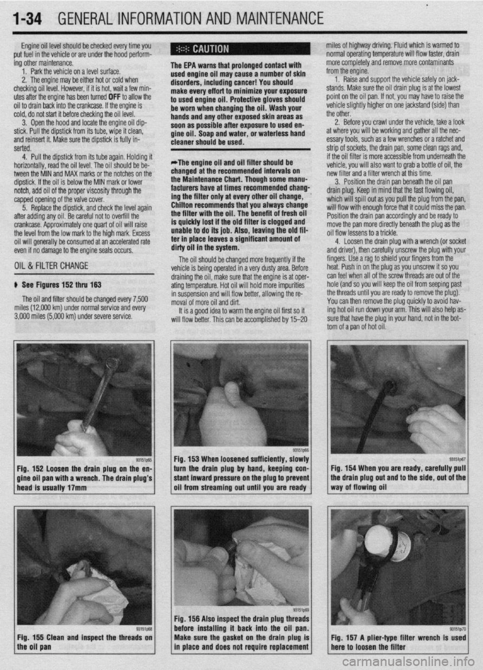
p See Figures 152 thru 153
The oil and filter should be changed every 7,500
miles (12,000 km) under normal service and every
3,000 miles (5,000 km) under severe service.
93151p-55 Fig. 152 loosen the drain plug on the en-
a wrench. The drain plug’s 3. Position the drain pan beneath the oil pan
drain plug. Keep in mind that the fast flowing oil,
which will spill out as you pull the plug from the pan,
will flow with enough force that it could miss the pan.
Position the drain pan accordingly and be ready to
move the pan more directly beneath the plug as the
oil flow lessens to a trickle.
4. Loosen the drain ~lua with a wrench (or socket
and driver), then carefuliy unscrew the plug with your
fingers. Use a rag to shield your fingers from the
heat. Push in on the plug as you unscrew it so you
draining the oil, make sure that the engine is at oper- can feel when all of the screw threads are out of the
ating temperature. Hot oil will hold more impurities hole (and so you will keep the oil from seeping past
in suspension and will flow better, allowing the re- the threads until you are ready to remove the plug).
moval of more oil and dirt. You can then remove the plug quickly to avoid hav-
It is a good idea to warm the engine oil first so it ing hot oil run down your arm. This will also help as-
will flow better. This can be accomolished bv 15-20 sure that have the plug in your hand, not in the bot-
tom of a pan of hot oil.
Fig. 153 When loosened sufficiently, slowly
turn the drain plug by hand, keeping con- Fig. 154 When you are ready, carefully pull
Fig. 156 Also inspect the drain plug th
before installing it back into the oil
Fig. 155 Clean and inspect the threads on
the oil pan Make sure the gasket on the drain plug is
in place and does not require replacement Fig. 157 A plier-type filter wrench Is used
here to loosen the filter
Page 52 of 408
ENGlNEELECTRliAL 2-5
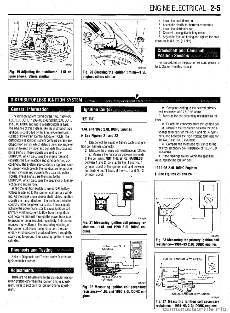
Fig. 19 Adjusting the distributor-1.5L en-
gine shown, others similar
4. Install the hold-down nut.
5. Attach the distributor harness connectors.
6. Install the distributor cap.
7. Connect the negative battery cable.
8. Adjust the ignition timing and tighten the hold-
down nut to 8 ft. Ibs. (11 Nm).
For procedures on the position sensors, please re-
fer to Section 4 in this manual.
The ignition system found on the 1.6L, 1997-60
1.8L, 2.OL DOHC, 1999-00 2.4L SOHC, 2.4L DOHC,
and 3.OL DOHC engines is a distributorless type.
The advance of this system, like the distributor type
ignition, is controlled by the Engine Control Unit
(ECU) or Powertrain Control Module (PCM). The
distributorless ignition system contains a crank an-
gle/position sensor which detects the crank angle or
position to each cylinder and converts this data into
pulse signals. These signals are sent to the
ECLVPCM, which calculates the engine rpm and
regulates the fuel injection and ignition timing ac-
cordingly. The system also contains a top dead cen-
ter sensor which detects the top dead center position
of each cylinder and converts this data into pulse
signals. These signals are then sent to the
ECU/PCM, which calculates the sequence of fuel in-
jection and engine rpm.
When the ignition switch is turned ON, battery
voltage is applied to the ignition coil primary wind-
ing. As the crank angle sensor shaft rotates, ignition
signals are transmitted from the multi port injection
control unit to the power transistor. These signals
activate the power transistor to cause ignition coil
primary winding current to flow from the ignition
coil negative terminal through the power transistor
to ground or be interrupted, repeatedly. This action
induces high voltage in the secondary winding of
the ignition coil. From the ignitron coil, the sec-
ondary winding current produced flows through the
spark plug to ground, thus causing ignition in each
cylinder.
Refer to Diagnosis and Testing under Distributor
Ignition in this section,
There are no adjustments to the distributorless ig-
nition system other than the ignition timing adjust-
ment. Refer to section 1 for ignition timing adjust-
ment.
TESTING
1.6L and 1990 2.OL DOHC Engines
6 See Figures 21 and 22
1. Disconnect the negative battery cable and igni-
tion coil harness connector.
2. Measure the primary coil resistance as follows:
a. Measure the resistance between terminals
of the coil pack,
NOT THE WIRE HARNESS, between 4 and 2 (coils at the No. 1 and No. 4
cylinder srdes) of the ignition coil, and between
terminals 4 and
1 (coils at the No. 2 and No. 3
cylinder sides).
93152go9 Fig. 21 Measuring ignition coil primary re-
sistance-1.6L and 1990 2.OL DDHC en-
gines
.
For No 1 and No. 4
cvlmders
Fig. 22 Measuring ignition coil secondary
resistance-l .6L and 1990 2.OL DOHC en-
gines
b. Compare reading to the desrred primary
coil resistance of 0.77-0.95 ohms.
3. Measure the coil secondary resistance as fol-
lows:
c. Detach the connector from the ignition coil.
d. Measure the resistance between the high-
voltage terminals for the No. 1 and No. 4 cylin-
ders, and between the high-voltage terminals for
the No. 2 and No. 3 cylinders.
e. Compare the measured resistance to the
desired secondary coil resistance of 10.3-13.9
kilo-ohms.
4. If the readings are not within the specified
value, replace the ignition coil.
1991-!I3 2.OL DDHC Engines
# See Figures 23 and 24
n 0
Fig. 23 Measuring the primary ignition coil
resistance-1991-93 2.OL DOHC enoines
I I
FOR NO 1 AND NO. 4 CYLINDERS
Id
FOR NO. 2 AND NO. 3 CYUNDERS
89572611
Fig. 24 Measuring ignition coil secondary
resistance-1991-93 2.OL DOHC engines
Page 87 of 408
3-26 ENGINEANDENGINEOVERHAUL
18. Remove the self-locking nuts and the small
retaining bolt holding the exhaust pipe to the bottom
of the exhaust manifold. Separate the pipe from the
manifold and remove the gasket.
19. Remove the bolts holding the support brace
to the bottom of the intake manifold.
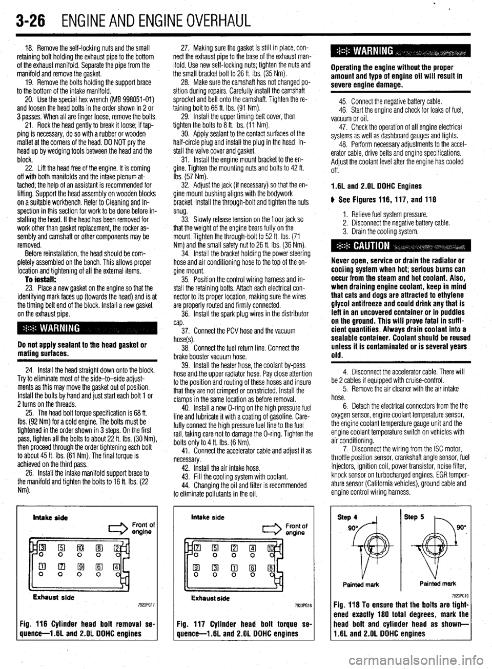
20. Use the special hex wrench (MB 998051-01)
and loosen the head bolts in the order shown in 2 or
3 passes. When all are finger loose, remove the bolts.
21. Rock the head gently to break it loose; if tap-
ping is necessary, do so with a rubber or wooden
mallet at the corners of the head. DO NOT pry the
head up by wedging tools between the head and the
block.
22. Lift the head free of the engine. It is coming
off with both manifolds and the intake plenum at-
tached; the help of an assistant is recommended for
lifting. Support the head assembly on wooden blocks
on a suitable workbench. Refer to Cleaning and In-
spection in this section for work to be done before in-
stalling the head. If the head has been removed for
work other than gasket replacement, the rocker as-
sembly and camshaft or other components may be
removed.
Before reinstallation, the head should be com-
pletely assembled on the bench. This allows proper
location and tightening of all the external items.
To install: 23. Place a new gasket on the engine so that the
identifying mark faces up (towards the head) and is at
the timing belt end of the block. Install a new gasket
on the exhaust pipe.
Do not apply sealant to the head gasket or
mating surfaces.
24. Install the head straight down onto the block.
Try to eliminate most of the side-to-side adjust-
ments as this may move the gasket out of position.
Install the bolts by hand and just start each bolt 1 or
2 turns on the threads.
25. The head bolt torque specification is 68 ft.
Ibs. (92 Nm) for a cold engine. The bolts must be
tightened in the order shown in 3 steps. On the first
pass, tighten all the bolts to about 22 ft. Ibs. (30 Nm),
then proceed through the order tightening each bolt
to about 45 ft. Ibs. (61 Nm). The final torque is
achieved on the third pass.
26. Install the intake manifold support brace to
the manifold and tighten the bolts to 16 ft. Ibs. (22
Nm). 27. Making sure the gasket is still in place, con-
nect the exhaust pipe to the base of the exhaust man-
ifold. Use new self-locking nuts; tighten the nuts and
the small bracket bolt to 26 ft. Ibs. (35 Nm).
28. Make sure the camshaft has not changed po-
sition during repalrs. Carefully install the camshaft
sprocket and belt onto the camshaft. Tighten the re-
taining bolt to 66 ft. Ibs. (91 Nm).
29. Install the upper timing belt cover, then
tighten the bolts to 8 ft. Ibs. (11 Nm).
30. Apply sealant to the contact surfaces of the
half-circle plug and install the plug in the head In-
stall the valve cover and gasket.
31. Install the engine mount bracket to the en-
gine. Tighten the mounting nuts and bolts to 42 ft.
Ibs. (57 Nm).
32. Adjust the jack (if necessary) so that the en-
gine mount bushing aligns with the bodywork
bracket. Install the through-bolt and tighten the nuts
snug.
33. Slowly release tension on the floor jack so
that the weight of the engine bears fully on the
mount. Tighten the through-bolt to 52 ft. Ibs. (71
Nm) and the small safety nut to 26 ft. tbs. (36 Nm).
34. Install the bracket holding the power steering
hose and air conditioning hose to the top of the en-
gine mount.
35. Position the control wiring harness and in-
stall the retaining bolts. Attach each electrical con-
nector to its proper location, making sure the wires
are properly routed and firmly connected.
36. Install the spark plug wires in the distributor
cap.
37. Connect the PCV hose and the vacuum
hose(s).
38. Connect the fuel return line. Connect the
brake booster vacuum hose.
39. Install the heater hose, the coolant by-pass
hose and.the upper radiator hose. Pay close attention
to the position and routing of these hoses and insure
that they are not crimped or constricted. Install the
clamps in the same location as before removal.
40. Install a new O-ring on the high pressure fuel
line and lubricate it with a coating of gasoline. Care-
fully connect the high pressure fuel line to the fuel
rail, taking care not to damage the O-ring. Tighten the
bolts only to 4 ft. Ibs. (6 Nm).
41. Connect the accelerator cable and adjust it as
necessary.
42. Install the air intake hose.
43. Fill the cooling system with coolant.
44. Changing the oil and filter is recommended
to eliminate pollutants in the oil.
Intake side
I Front of
engine
Exhaust side
Fig. 116 Cylinder head bolt removal se-
quence-l .6L and 2.OL DDHC engines intake
side
Front of
entine
Exhaust side 7923PG18
Fig. 117 Cylinder head bolt torque se-
quence-l .6L and 2.OL DDHC engines Operating the engine without the proper
amount and type of engine oil will result in
severe engine damage.
45. Connect the negative battery cable.
46. Start the engine and check for leaks of fuel,
vacuum or oil.
47. Check the operation of all engine electrical
systems as well as dashboard gauges and lights.
48. Perform necessary adjustments to the accel-
erator cable, drive belts and engine specifications.
Adjust the coolant level after the engine has cooled
Off.
1.6L and 2.OL DDHC Engines
ti See Figures 116,117, and 116
1. Relieve fuel system pressure.
2. Disconnect the negative battery cable.
3. Drain the cooling system.
Never open, service or drain the radiator or
cooling system when hot; serious burns can
occur from the steam and hot coolant. Also,
when draining engine coolant, keep in mind
that cats and dogs are attracted to ethylene
glycol antifreeze and could drink any that is
left in an uncovered container or in puddles
on the ground. This will prove fatal in suffi-
cient quantities. Always drain coolant into a
sealable container. Coolant should be reused
unless it is contaminated or is several years
old.
4. Disconnect the accelerator cable. There will
be 2 cables if equipped with cruise-control.
5. Remove the air cleaner with the air intake
hose.
6. Detach the electrical connectors from the the
oxygen sensor, engine coolant temperature sensor,
the engine coolant temperature gauge unit and the
engine coolant temperature switch on vehicles with
air conditioning.
7. Disconnect the wiring from the ISC motor,
throttle position sensor, crankshaft angle sensor, fuel
injectors, ignition coil, power transistor, noise filter,
knock sensor on turbocharged engines, EGR temper-
ature sensor (California vehicles), ground cable and
engine control wiring harness.
Painted mark Painted mark
Fig. 116 To ensure that the bolts are tight-
ened exactly 160 total degrees, mark the
11.6L and 2.OL DDHC engines head bolt and cylinder head as shown-
Page 117 of 408
3-56 ENGINEANDENGINEOVERHAUL
,
F C
F
t
. Fig.
220 Example of a badly deteriorated ex- 1 Fig. 221 inspect flanges for gaskets that
haust pipe have deteriorated and need replacement Fig. 222 Some systems, like this one, use
)ermit exhaust fumes to seep into the passenger
:ompartment. Inspect all mounting brackets and
bangers for deterioration, some models may have
ubber O-rings that can be overstretched and non-
supportive. These components will need to be re-
Ilaced if found. It has always been a practice to use a
)ointed tool to poke up into the exhaist system
vhere the deterioration spots are to see whether or
d they crumble. Some models may have heat shield
:overing certain parts of the exhaust system , it will
te necessary to remove these shields to have the ex-
laust visible for inspection also. Before removing any component of the exhaust
system, ALWAYS squirt a Liquid rust dissolving agent
onto the fasteners for ease of removal. A lot of
knuckle skin will be saved by following this rule. It
may even be wise to spray the fasteners and allow
them to sit overniqht.
Flange Type
b See Figure 224 tractor, which oflen means removal of the manifold it
self. Next, disconnect the component from the
mounting; slight twisting and turning may be re-
quired to remove the component completely from thr
vehicle. You may need to tap on the component with
a rubber mallet to loosen it. If all else fails, use a
hacksaw to sep; arate the parts. An oxy-acetylene cut-
ting torch may I 3e faster but the sparks are OANGER-
OUS near the fuel tank, ant 1 at the very least, acci-
dents could happen, result ing in damage to the
under-car parts, not to mei ition yourself.
3EPLACEMEMT
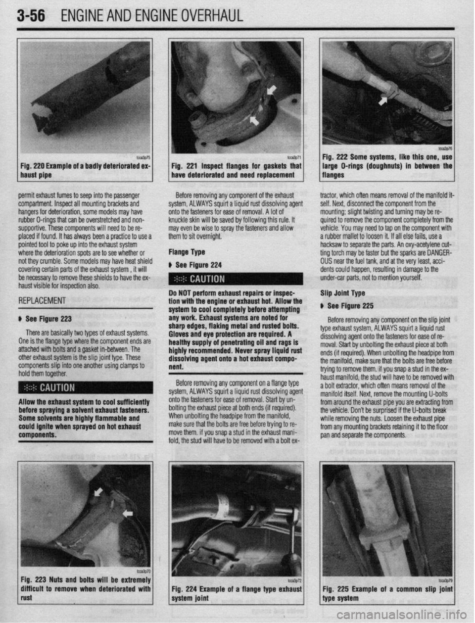
1 See Figure 223
There are basically two types of exhaust systems.
)ne is the flange type where the component ends are
attached with bolts and a gasket in-between. The
)ther exhaust system is the slip joint type. These
:omponents slip into one another using clamps to
iold them together. Do NOT perform exhaust repairs or inspec-
tion with the engine or exhaust hot. Allow the
system to cool completely before attempting
any work. Exhaust systems are noted for
sharp edges, flaking metal and rusted bolts.
Gloves and eye protection are required. A
healthy supply of penetrating oil and
rags is
highly recommended. Never spray liquid rust
dissolving agent onto a hot exhaust compo-
nent. Slip Joint Type
V See Figure 225
Before removing any component on the slip joint
type exhaust system, ALWAYS squirt a liquid rust
dissolving agent onto the fasteners for ease of re-
moval. Start by unbolting the exhaust piece at both
ends (if required). When unbolting the headpipe fron
the manifold, make sure that the bolts are free before
trying to remove them. if you snap a stud in the ex-
haust manifold. the stud will have to be removed wit1
Before removing any component on a flange type
system, ALWAYS squirt a liquid rust dissolving agent a bolt extractor, which often means removal of the
._ manifold itself. Next. remove the mountina U-bolts
liiow the exhaust system to cool sufficiently
Iefore spraying a solvent exhaust fasteners.
Some solvents are highly flammable and
:ould ignite when sprayed on hot exhauti
:omponents. onto the fasteners for ease of removal. Start by un-
bolting the exhaust piece at both ends (if required).
When unbolting the headpipe from the manifold,
make sure that the bolts are free before trying to re-
move them. if you snap a stud in the exhaust mani-
fold, the stud will have to be removed with a bolt ex-
ka3p70 Fig. 223 Nuts and bolts will be extremely
difflcuit to remove when deteriorated with
rust Fig. 224 Example of a flange type exhaust
system joint from around the exhaust pipe you are ext&ting from
the vehicle. Don’t be surprised if the U-bolts break
while removing the nuts. Loosen the exhaust pipe
from any mounting brackets retaining it to the floor
pan and separate the components.
Fig. 225 Example of a common slip joini
type system