4WD MITSUBISHI ECLIPSE 1990 User Guide
[x] Cancel search | Manufacturer: MITSUBISHI, Model Year: 1990, Model line: ECLIPSE, Model: MITSUBISHI ECLIPSE 1990Pages: 391, PDF Size: 15.27 MB
Page 39 of 391
BRAKES - Service Brakes 5-3
$eTandem (with level sensor)
(718)
Brake boosterTYpeEffective dia. of
y3tt$;ivacuum-boost type
powmermc&;der
Proportioning valve Type Dual type
(597)
kPa (psi)
Decompression 0. 3
(15/l 6)
Multiple-vacuum-boost type
c
4,200 (597)
TypeM-R44VM-R44V
cyhnxLy.53.9 (2’/8) 53.9 (2%)
Clearance Automatic Automati
c
I
TypeAD30PAD30P
Cyl~itl;.~. 30.1 (13/16) 30.1 (13/16)
Clearance Automatic Automatic
*:4WD
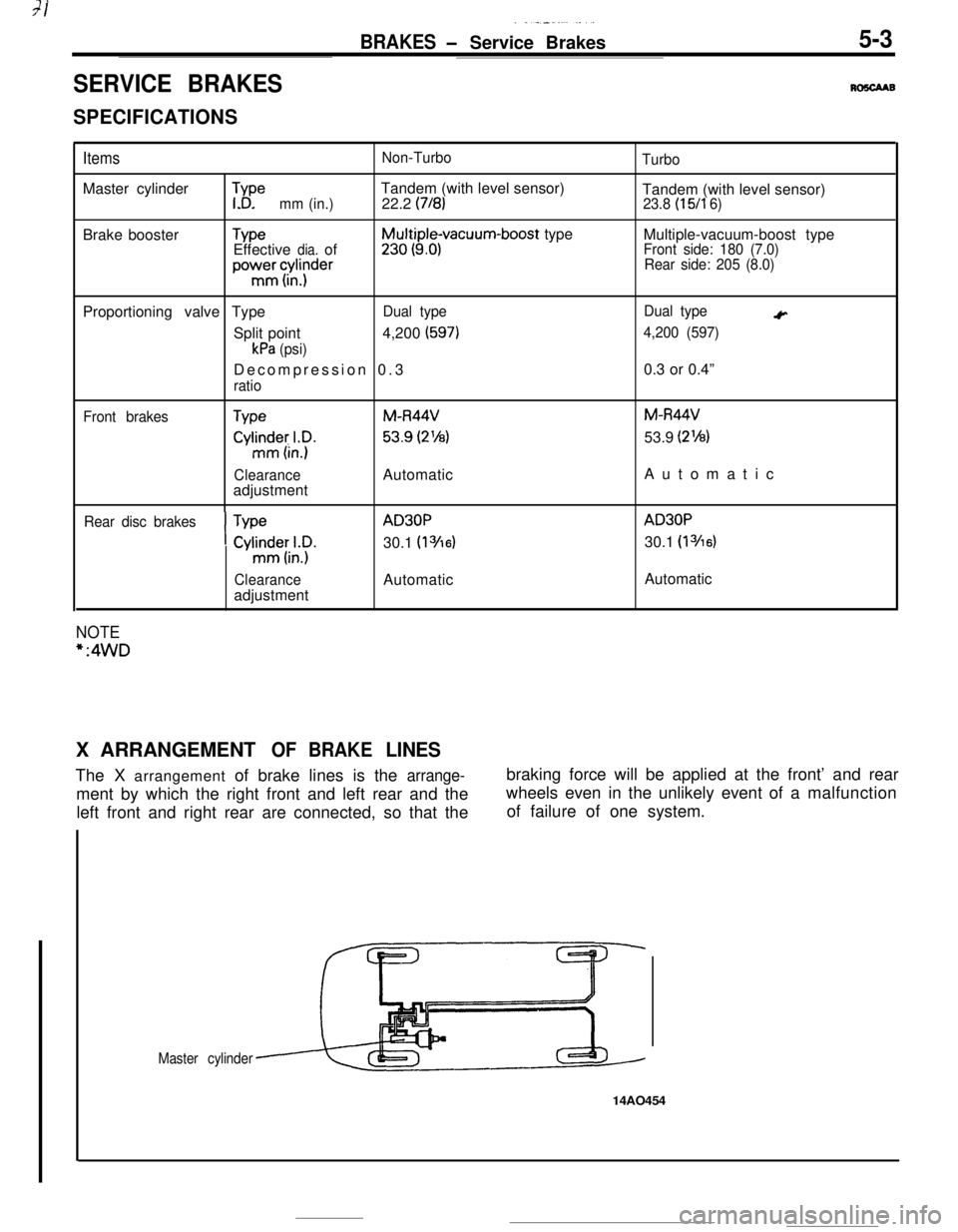
X
ARRANGEMENT OF BRAKE LINES
Page 41 of 391
7-.
BRAKES - Service Brakes5-5
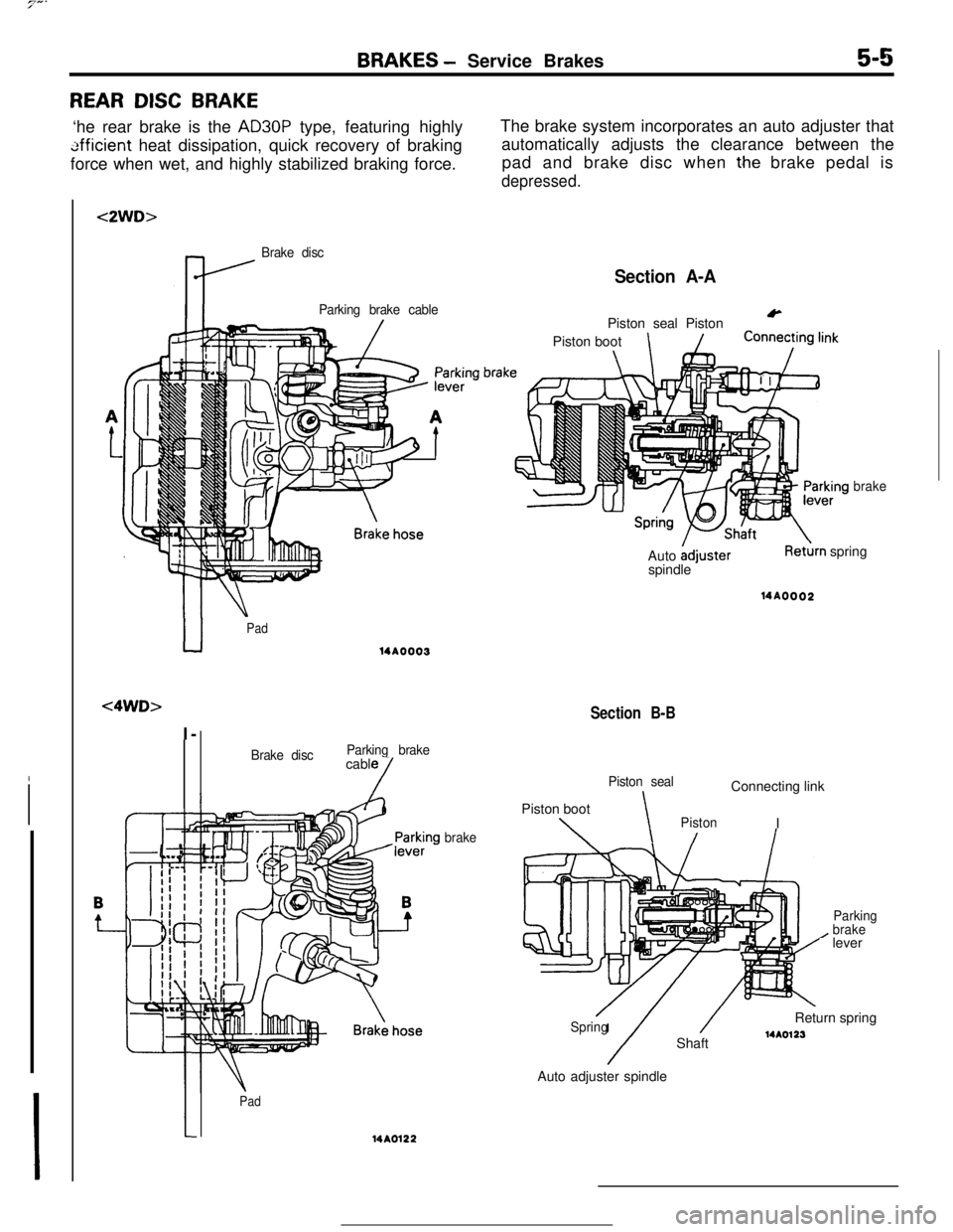
REAR DISC BRAKE‘he rear brake is the
AD30P type, featuring highly
tifficient heat dissipation, quick recovery of braking
force when wet, and highly stabilized braking force.The brake system incorporates an auto adjuster that
automatically adjusts the clearance between the
pad and brake disc when
t.he brake pedal is
depressed.
<2WD>
Brake disc
Parking brake cable
Section A-A
&
u
Pad
<4WD>I-
14A0003
Brake discParking brakecable
/
Pad14A0122
brake
brakPiston seal Piston
Piston boot
\
brakeAuto
AdjusterspindleRet&n spring14AOOO2
Section B-B
Piston sealConnecting link
Piston boot
\\PistonI
/
Parking
brakelever
/Spring
/
/Return spring
Shaft14A0123Auto adjuster spindle
Page 42 of 391
5-6BRAKES - Service Brakes
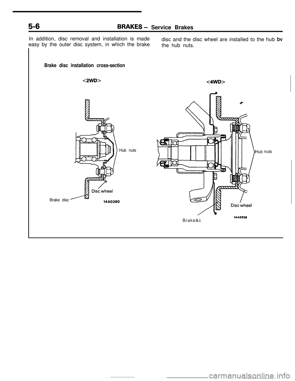
In addition, disc removal and installation is made
easy by the outer disc system, in which the brakedisc and the disc wheel are installed to the hub
bvthe hub nuts.
Brake disc installation cross-section<2WD>
<4WD>
Hub nuts
Brake disc14AO390Hubnuts
Brake&c
14AO622
Page 43 of 391
PARKING BRAKE
BRAKES- Parking Brake5-7
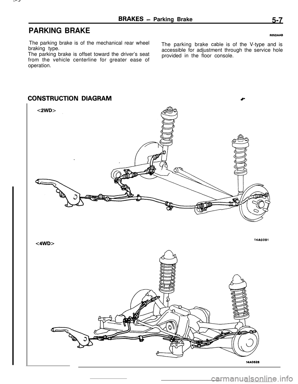
ROSDMBThe parking brake is of the mechanical rear wheel
braking type.The parking brake
cable is of the V-type and is
The parking brake is offset toward the driver’s seataccessible for adjustment through the service hole
provided in the floor console.
from the vehicle centerline for greater ease of
operation.CONSTRUCTION DIAGRAM
Y14AO391
<4WD>14A0626
Page 106 of 391
L1ENGINE
- Mounts9-21MOUNTS
Rost3u
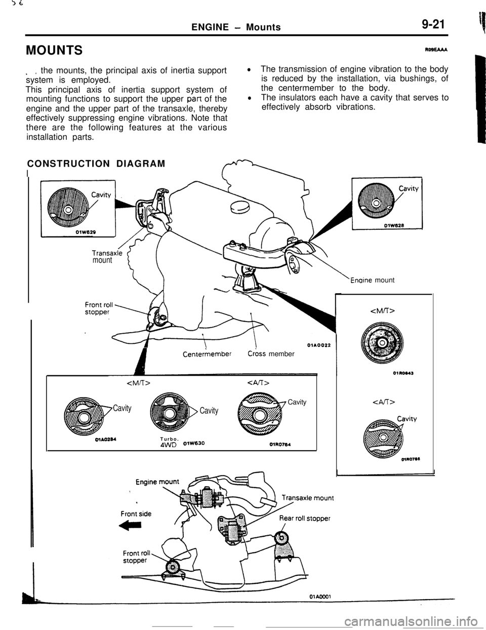
. *the mounts, the principal axis of inertia support
system is employed.
This principal axis of inertia support system of
mounting functions to support the upper
part of the
engine and the upper part of the transaxle, thereby
effectively suppressing engine vibrations. Note that
there are the following features at the various
installation parts.
lThe transmission of engine vibration to the body
is reduced by the installation, via bushings, of
the centermember to the body.
lThe insulators each have a cavity that serves to
effectively absorb vibrations.
CONSTRUCTION DIAGRAM
I
Transaxlemount
‘i::
+g
/v 1b-8
8-,
Enaine mount
A
CenterkemberC&s member
Cavity
CavityCavityolAO284Turbo.
4WD 0lW630OlRO764
Page 117 of 391
_ --_-_ .-..__FUEL SYSTEM
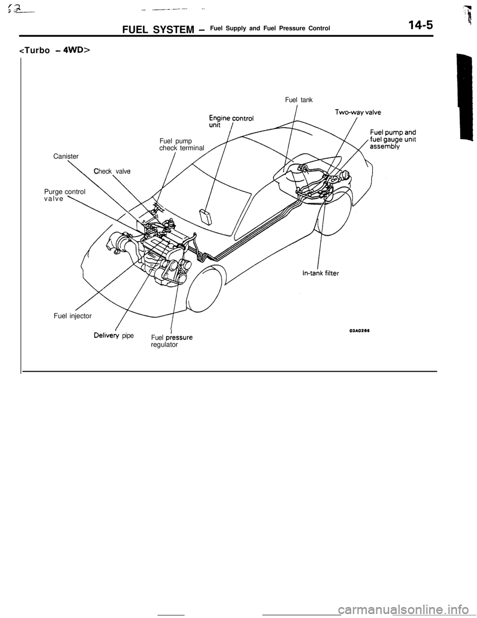
-Fuel Supply and Fuel Pressure Control14-5Canister
Fuel tank
Fuel pumpcheck terminal
\
Check valvePurge control
valve
\Fuel injectorDelivery
pipe
Fuel p:essure
regulator
Page 119 of 391
FUEL SYSTEM -Fuel Supply and Fuel Pressure Control14-7FUEL TANK
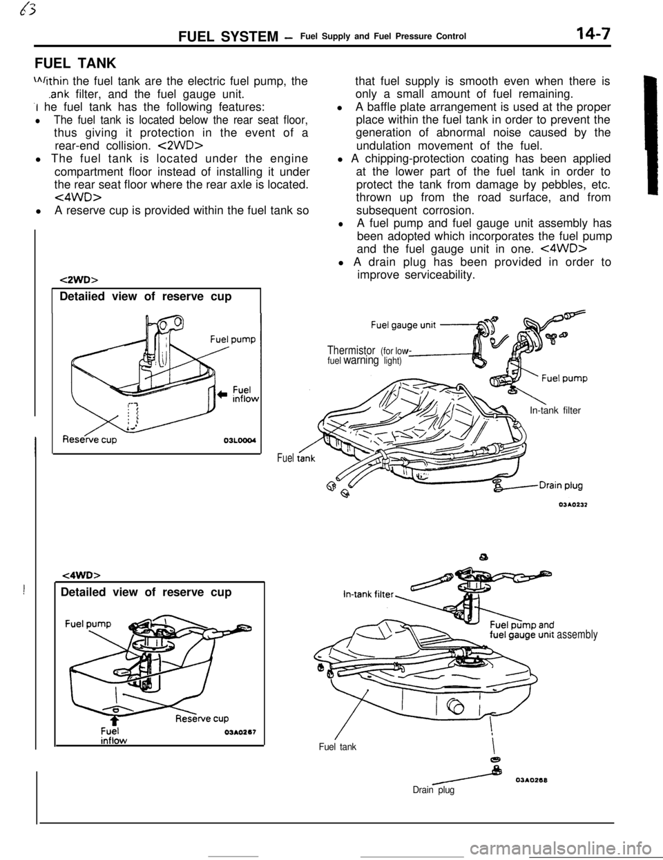
m/ithin the fuel tank are the electric fuel pump, the
.ank filter, and the fuel gauge unit.
-I he fuel tank has the following features:
lThe fuel tank is located below the rear seat floor,thus giving it protection in the event of a
rear-end collision.
<2WD>l The fuel tank is located under the engine
compartment floor instead of installing it under
the rear seat floor where the rear axle is located.
<4WD>lA reserve cup is provided within the fuel tank so
!Detailed view of reserve cup
t2WD>Detaiied view of reserve cup
t4WD>
Fuel03AO267
Fuelthat fuel supply is smooth even when there is
only a small amount of fuel remaining.
lA baffle plate arrangement is used at the proper
place within the fuel tank in order to prevent the
generation of abnormal noise caused by the
undulation movement of the fuel.
l A chipping-protection coating has been applied
at the lower part of the fuel tank in order to
protect the tank from damage by pebbles, etc.
thrown up from the road surface, and from
subsequent corrosion.
lA fuel pump and fuel gauge unit assembly has
been adopted which incorporates the fuel pump
and the fuel gauge unit in one.
<4WD>l A drain plug has been provided in order to
improve serviceability.
Thermistor (for low
fuel warning light)In-tank filter
Fuel tankI
e
/ 03AO268
Drain plug
assembly
Page 201 of 391
.-_. -
17-8REAR SUSPENSION <4WD> - Geneal information
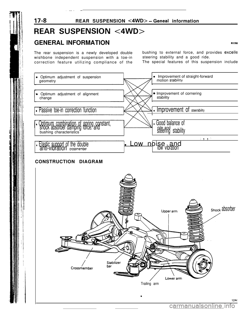
REAR SUSPENSION <4WD>GENERAL INFORMATION
Rl7BEThe rear suspension is a newly developed double
wishbone independent suspension with a toe-in
correction feature utilizing compliance of thebushing to external force, and provides
excellesteering stability and a good ride.
The special features of this suspension include
l Optimum adjustment of suspensiongeometry
l Optimum adjustment of alignment
change
0 Passive toe-in correction function
l Optimum combination of spring constant,
shock absorber damping force. andbushing characteristics
l Elastic support of the doubleanti-vibration croSsmemberl Improvement of straight-forward
motion stability
0 Improvement of cornering
stability
l Improvement of steerability
l Good balance ofride andsteering stability
( , , :l Low noise and
low vibrationCONSTRUCTION DIAGRAM
absorber
Trailing arm
.
12AC
Page 202 of 391
_ -. ..__ .-
REAR SUSPENSION
<4WD> - Geneal (nformation
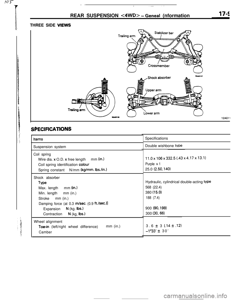
THREE SIDE VIEWS
Trailil
12AOll
SPECiFiCATiONSItems
Suspension system
Coil springWire dia. x O.D.
x free lengthmm (in.)Coil spring identification
colourSpring constantN/mm
(kg/mm. Ibs.An.1
Shock absorberType
Max. lengthmm
(in.)Min. length
mm (in.)Stroke
mm (in.)
Damping force (at 0.3
m/set. (0.9 ft./sec.)l
Expansion
N (kg. Ibs.)Contraction
N (kg, Ibs.)Wheel alignment
Toe-in (left/right wheel difference)mm (in.)
CamberSpecifications
Double wishbone tvpe
11.0x106x332.5(.43x4.17x13.1)
Purple x 125.0
(2.50, 140)Hydraulic, cylindrical double-acting
We
568 (22.4)380
(15.0)
188 (7.4)900
(90. 198)300
(30.66)3.6
f 3 (.14 2 .I21
-1”33’ + 30’
Page 203 of 391
REAR SUSPENSION <4WD> - Wheel Alignment
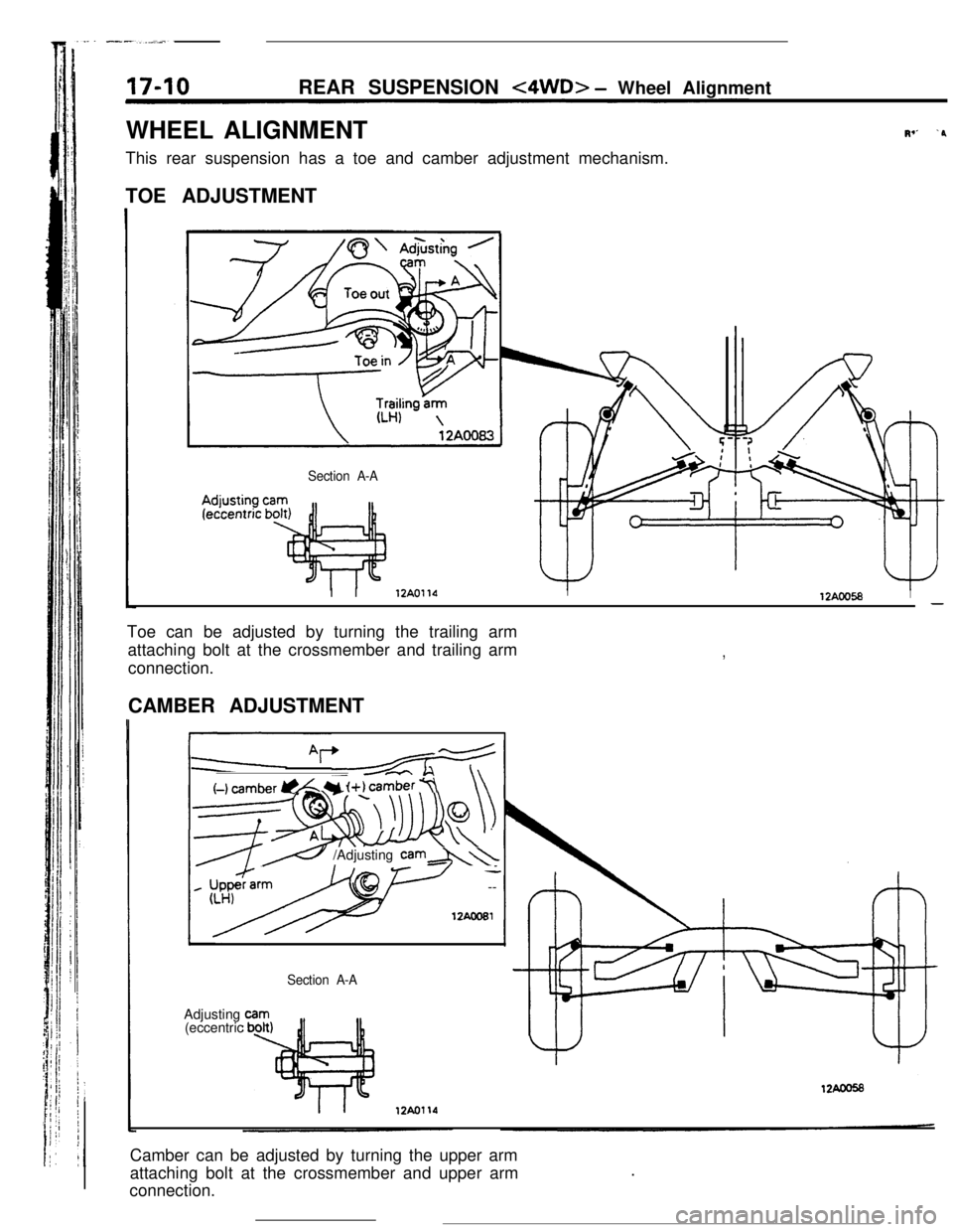
WHEEL ALIGNMENT
This rear suspension has a toe and camber adjustment mechanism.
TOE ADJUSTMENT
Section A-A
Iv’ ‘PI I
12AOllOI12AOO58I-Toe can be adjusted by turning the trailing arm
attaching bolt at the crossmember and trailing arm
connection.
,CAMBER ADJUSTMENT
I
(-1 cam&r @L Y i+) camber 7\\
__cc \
----7--w
’ --
12AcoEl
e /Adjusting cam&\\Adjusting
(eccentric
Section A-ACamber can be adjusted by turning the upper arm
attaching bolt at the crossmember and upper arm
connection..