fuel pump MITSUBISHI ECLIPSE 1990 Service Manual
[x] Cancel search | Manufacturer: MITSUBISHI, Model Year: 1990, Model line: ECLIPSE, Model: MITSUBISHI ECLIPSE 1990Pages: 391, PDF Size: 15.27 MB
Page 67 of 391
. . .&L : __,ELECTRICAL
- Inspection Terminal
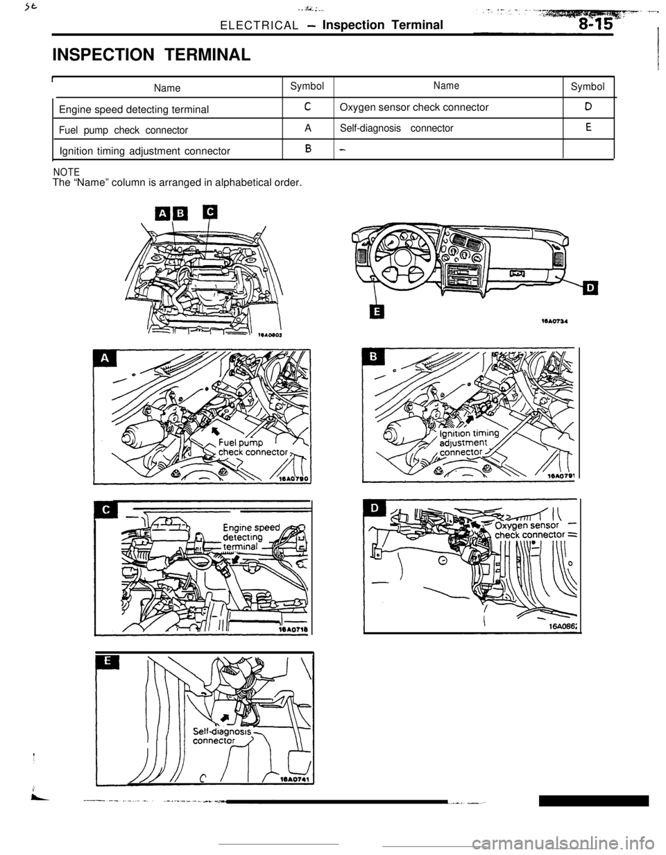
INSPECTION TERMINAL
INameSymbolNameEngine speed detecting terminal
COxygen sensor check connector
Fuel pump check connectorASelf-diagnosis connectorIgnition timing adjustment connector
B -
NOTEThe “Name” column is arranged in alphabetical order.
Symbol
D
E16Ao734
Page 87 of 391
=--Y
jl
1 /
i "
_. ---“._ _ _ ._ ..-..+_LI_y_--- -
9-2ENGINE- General Information
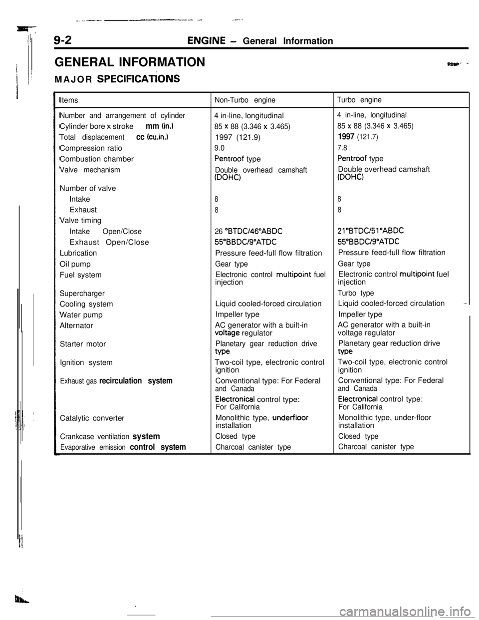
GENERAL INFORMATION
MAJOR
SPEClFlCATiONS
Row- -
Items
Number and arrangement of cylinderCylinder bore x stroke
mm (in.)
Total displacementcc (cu.in.1Compression ratio
Combustion chamber
Valve mechanismNumber of valve
Intake
Exhaust
Valve timing
IntakeOpen/CloseExhaust Open/Close
Lubrication
Oil pump
Fuel system
SuperchargerCooling system
Water pump
Alternator
Starter motor
Ignition system
Exhaust gas recirculation systemCatalytic converter
Crankcase ventilation system
Evaporative emission control system
Non-Turbo engineTurbo engine4 in-line, longitudinal
4 in-line, longitudinal
85 x
88 (3.346 x 3.465)85 x 88 (3.346 x 3.465)1997 (121.9)
1997 (121.7)
9.07.8
Pentroof typePentroof type
Double overhead camshaftDouble overhead camshaft
(DOHC)(DOHC)
88
88
26 “BTDU46”ABDC21”BTDC/Sl”ABDC56BBDUS”ATDC55”BBDUS”ATDC
Pressure feed-full flow filtrationPressure feed-full flow filtration
Gear typeGear type
Electronic control multipoint
fuelElectronic control multipoint fuel
injectioninjection
Turbo typeLiquid cooled-forced circulationLiquid cooled-forced circulation
-Impeller typeImpeller type
AC generator with a built-involtage regulatorAC generator with a built-in
voltage regulator
Planetary gear reduction drivePlanetary gear reduction drivetype
Two-coil type, electronic controlTwo-coil type, electronic control
ignitionignition
Conventional type: For FederalConventional type: For Federal
and Canadaand Canada
Electronical control type:Electronical control type:
For CaliforniaFor CaliforniaMonolithic type,
under-floorMonolithic type, under-floor
installationinstallation
Closed typeClosed type
Charcoal canister typeCharcoal canister type
I
Page 115 of 391
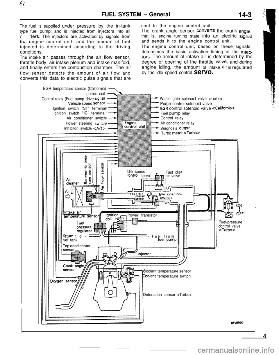
FUEL SYSTEM - General14-3The fuel is supplied under pressure by the in-tanksent to the engine control unit.
type fuel pump, and is injected from injectors into allThe crank angle sensor converts the crank
angle,
cders. The injectors are activated by signals fromthat is, engine turning state into an electric signal
tk, engine control unit, and the amount of fueland sends it to the engine control unit.
injected is determined according to the drivingThe engine control unit, based on these signals,
conditions.determines the basic activation timing of the
injec-The intake air passes through the air flow sensor,
tars. The amount of intake air is determined by the
throttle body, air intake plenum and intake manifold,degree of opening of the throttle
valye,, and during
and finally enters the combustion chamber. The airengine idling, the amount of intake
arr IS regulated
flow sensor detects the amount of air flow and
by the idle speed control servo.converts this data to electric pulse signals that are
EGR temperature sensor (California) 7
Waste gate solenoid valve
Purge control solenoid valve
EGR control solenoid valve
Control relay
Air conditioner relay
Diagnosis output
Ignition coil
Control relay (Fuel pump drive
signal)Vehicle speed
SensorIgnition switch “ST” terminal
Ignition switch
‘IG” terminal
Air conditioner switch
Power steering
switch
Inhibitor switch
Idle speed
ontrol servoFast idle
air valve
-Throttle
&r -kilo m-i&inn’Power transistorleturn to-
uel tank- Fuel from
Coolant temperature sensor
Coolant temperature switchFuel-pressure
control valve
4
Page 116 of 391
FUEL SYSTEM- duel Supply and Fuel Pressure Control
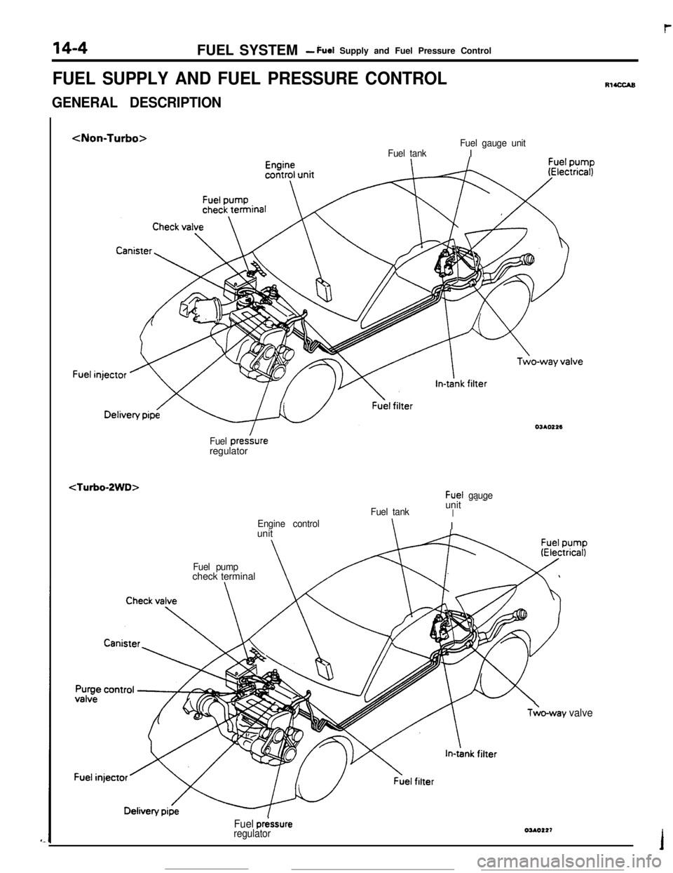
FUEL SUPPLY AND FUEL PRESSURE CONTROL
GENERAL DESCRIPTION
Fuel tankFuel gauge unitIOJAOt26
Fuel presbreregulator
Fuel tankunit - -IEngine control\I
unit
Fuel pumpcheck terminal\
TLo-way valve
Fuel p&sure
regulatorOUO227
RIUXAB
Page 117 of 391
_ --_-_ .-..__FUEL SYSTEM
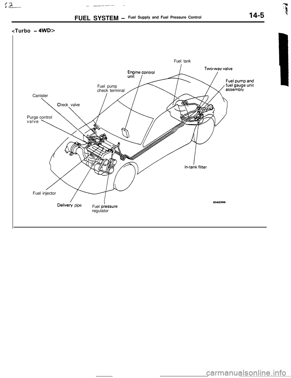
-Fuel Supply and Fuel Pressure Control14-5Canister
Fuel tank
Fuel pumpcheck terminal
\
Check valvePurge control
valve
\Fuel injectorDelivery
pipe
Fuel p:essure
regulator
Page 118 of 391
14-6FUEL SYSTEM -Fuel Supply and Fuel Pressure Control
intake manifold/I\
Engine
Fuel
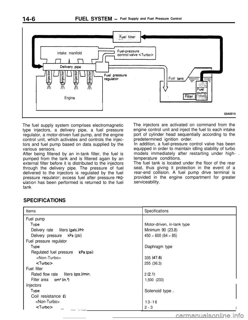
03AOOlOThe fuel supply system comprises electromagnetic
type injectors, a delivery pipe, a fuel pressure
regulator, a motor-driven fuel pump, and the engine
control unit, which activates and controls the injec-
tors and fuel pump based on data supplied by the
various sensors.
After being filtered by an in-tank filter, the fuel is
pumped from the tank and is filtered again by an
external filter before it is distributed to the injectors
through the delivery pipe. The pressure of fuel
delivered to the injectors is regulated by the fuel
pressure
reoulator; excess fuel after pressure reg-ulation has been performed is returned to the fuel
tankThe injectors are activated on command from the
engine control unit and inject the fuel to each intake
port of cylinder head sequentially according to the
predetermined ignition order.
In addition, a fuel-pressure control valve has been
equipped in order to maintain idling stability of turbo
models immediately after restarting under high- -
temperature conditions.
The fuel tank is located under the floor of the rear
seat, thus giving it protection in the event of a
rear-end collision. A fuel pump drive terminal is
provided in the engine compartment for greater
serviceability.
-
SPECIFICATIONSItems
Fuel pump
Type
Delivery rate
liters (gals.VHr
Delivery pressurekPa (psi)
Fuel pressure regulator
Tvw
Regulated fuel pressurekPa (psi)
Fuel filter
Rated flow rate
liters (qts.)/min.
Filter areacm’ (in.‘)
Injectors
TypeCoil resistance
n
--
.- -_-_
SpecificationsMotor-driven, in-tank type
Minimum 90 (23.8)
450 - 600 (64 - 85)
Diaphragm type
335 (47.6)
255 (36.3)
2
(2.1)
1,500 (233)Solenoid type
,.13-16
2-3
I
Page 119 of 391
FUEL SYSTEM -Fuel Supply and Fuel Pressure Control14-7FUEL TANK
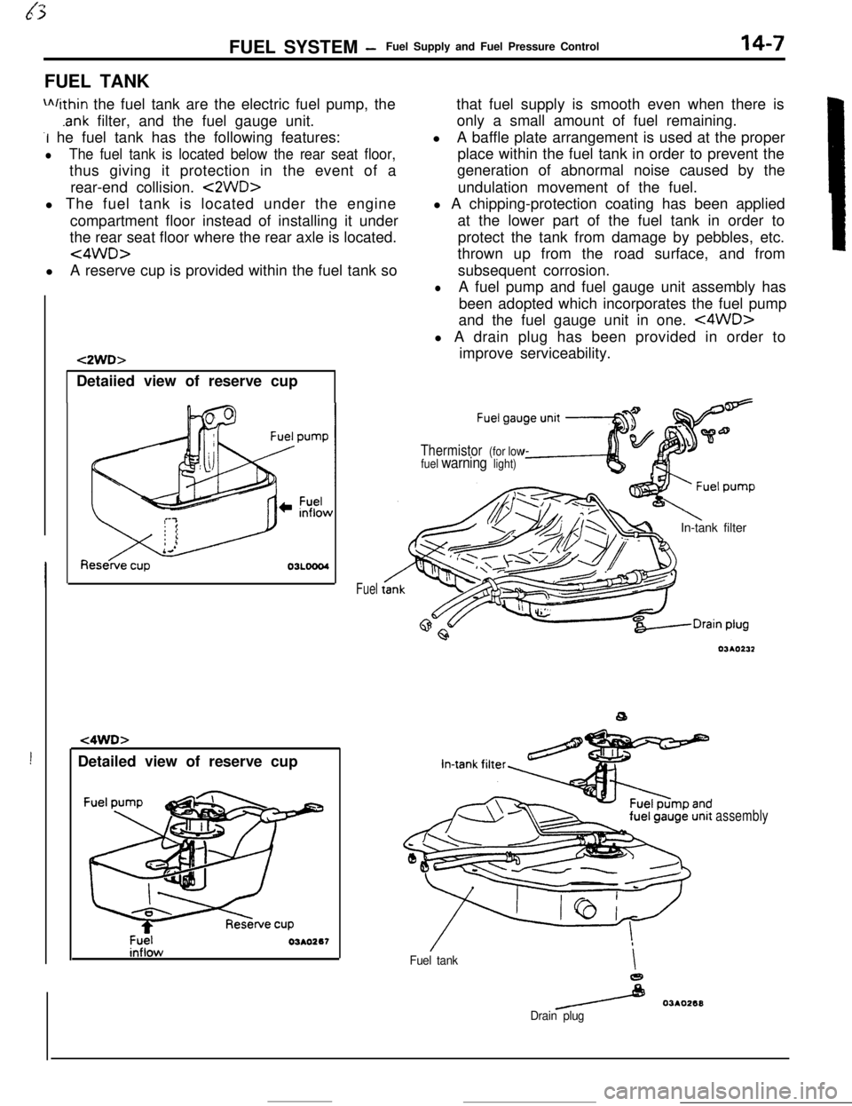
m/ithin the fuel tank are the electric fuel pump, the
.ank filter, and the fuel gauge unit.
-I he fuel tank has the following features:
lThe fuel tank is located below the rear seat floor,thus giving it protection in the event of a
rear-end collision.
<2WD>l The fuel tank is located under the engine
compartment floor instead of installing it under
the rear seat floor where the rear axle is located.
<4WD>lA reserve cup is provided within the fuel tank so
!Detailed view of reserve cup
t2WD>Detaiied view of reserve cup
t4WD>
Fuel03AO267
Fuelthat fuel supply is smooth even when there is
only a small amount of fuel remaining.
lA baffle plate arrangement is used at the proper
place within the fuel tank in order to prevent the
generation of abnormal noise caused by the
undulation movement of the fuel.
l A chipping-protection coating has been applied
at the lower part of the fuel tank in order to
protect the tank from damage by pebbles, etc.
thrown up from the road surface, and from
subsequent corrosion.
lA fuel pump and fuel gauge unit assembly has
been adopted which incorporates the fuel pump
and the fuel gauge unit in one.
<4WD>l A drain plug has been provided in order to
improve serviceability.
Thermistor (for low
fuel warning light)In-tank filter
Fuel tankI
e
/ 03AO268
Drain plug
assembly
Page 120 of 391
14-8
rFUEL SYSTEM
-Fuel Supply and Fuel Pressure Control
FUEL PUMP
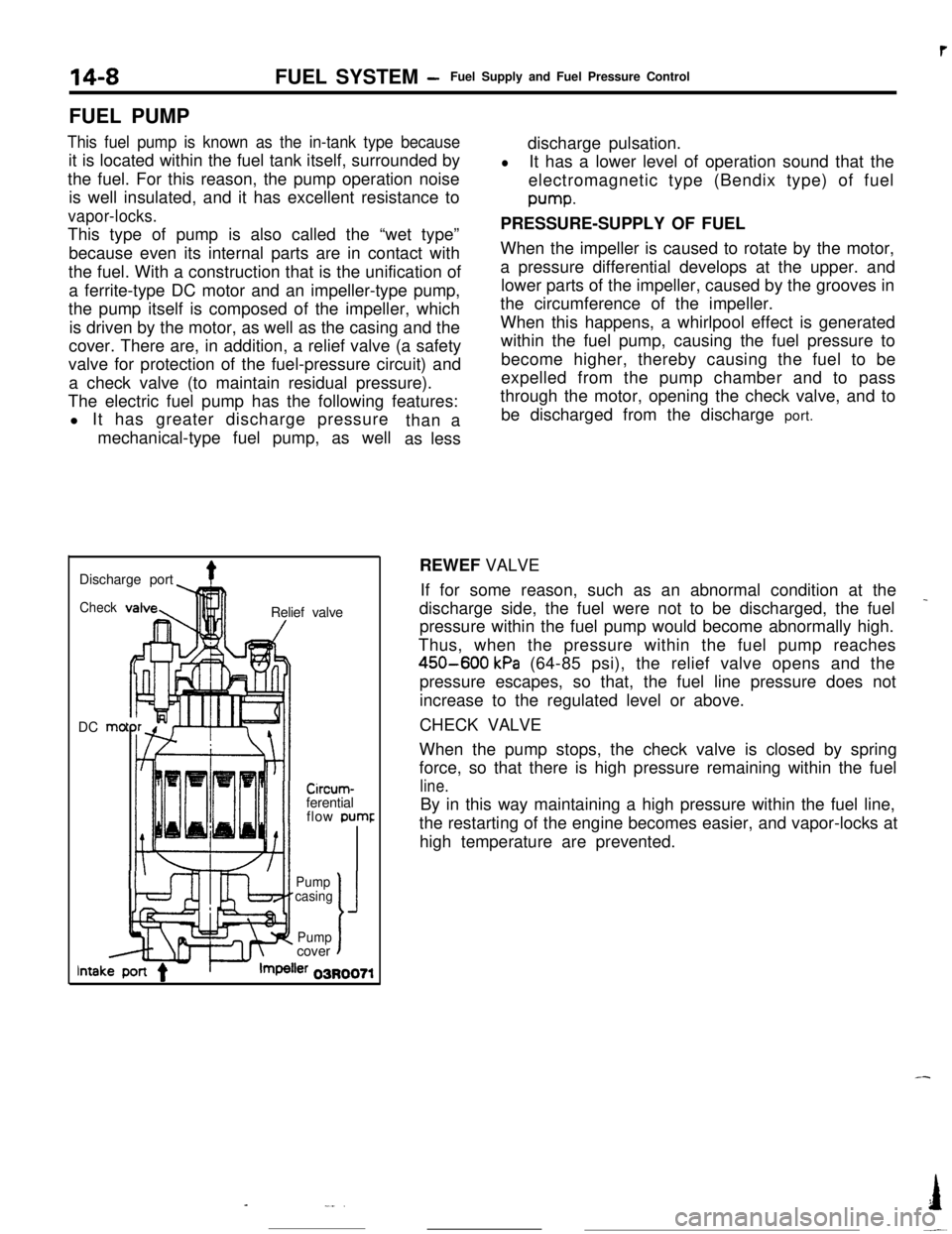
This fuel pump is known as the in-tank type becauseit is located within the fuel tank itself, surrounded by
the fuel. For this reason, the pump operation noise
is well insulated, and it has excellent resistance to
vapor-locks.This type of pump is also called the “wet type”
because even its internal parts are in contact with
the fuel. With a construction that is the unification of
a ferrite-type DC motor and an impeller-type pump,
the pump itself is composed of the impeller, which
is driven by the motor, as well as the casing and the
cover. There are, in addition, a relief valve (a safety
valve for protection of the fuel-pressure circuit) and
a check valve (to maintain residual pressure).
The electric fuel pump has the following features:
l It has greater discharge pressure
mechanical-type fuel pump, as wellthan a
as lessdischarge pulsation.
lIt has a lower level of operation sound that the
electromagnetic type (Bendix type) of fuelpump.
PRESSURE-SUPPLY OF FUEL
When the impeller is caused to rotate by the motor,
a pressure differential develops at the upper. and
lower parts of the impeller, caused by the grooves in
the circumference of the impeller.
When this happens, a whirlpool effect is generated
within the fuel pump, causing the fuel pressure to
become higher, thereby causing the fuel to be
expelled from the pump chamber and to pass
through the motor, opening the check valve, and to
be discharged from the discharge port.
Discharge port
4Check!nRelief valve
DC mo
-lllll1 I/
Circum-ferential
flow pumr
II’ f-Pump
casing
J
Pumpcovert
lntakler 03R0071REWEF VALVE
If for some reason, such as an abnormal condition at the
_discharge side, the fuel were not to be discharged, the fuel
pressure within the fuel pump would become abnormally high.
Thus, when the pressure within the fuel pump reaches
450-600 kPa (64-85 psi), the relief valve opens and the
pressure escapes, so that, the fuel line pressure does not
increase to the regulated level or above.
CHECK VALVE
When the pump stops, the check valve is closed by spring
force, so that there is high pressure remaining within the fuel
line.By in this way maintaining a high pressure within the fuel line,
the restarting of the engine becomes easier, and vapor-locks at
high temperature are prevented.
-
-_..I
-~
Page 121 of 391
FUEL SYSTEM -Fuel Supply and Fuel Pressure Control14-9
03Poo4:Diaphragm
from intake
4Fuel from delivery pipe
4m
B(42.7)QQ
2
sl -196 2
(26.4) g
t
$!a d
9
0)Positive5 z‘. pressure
(E.2)
w
FUEL FILTERA high-pressure type filter is installed at the delivery end of the
fuel pump.
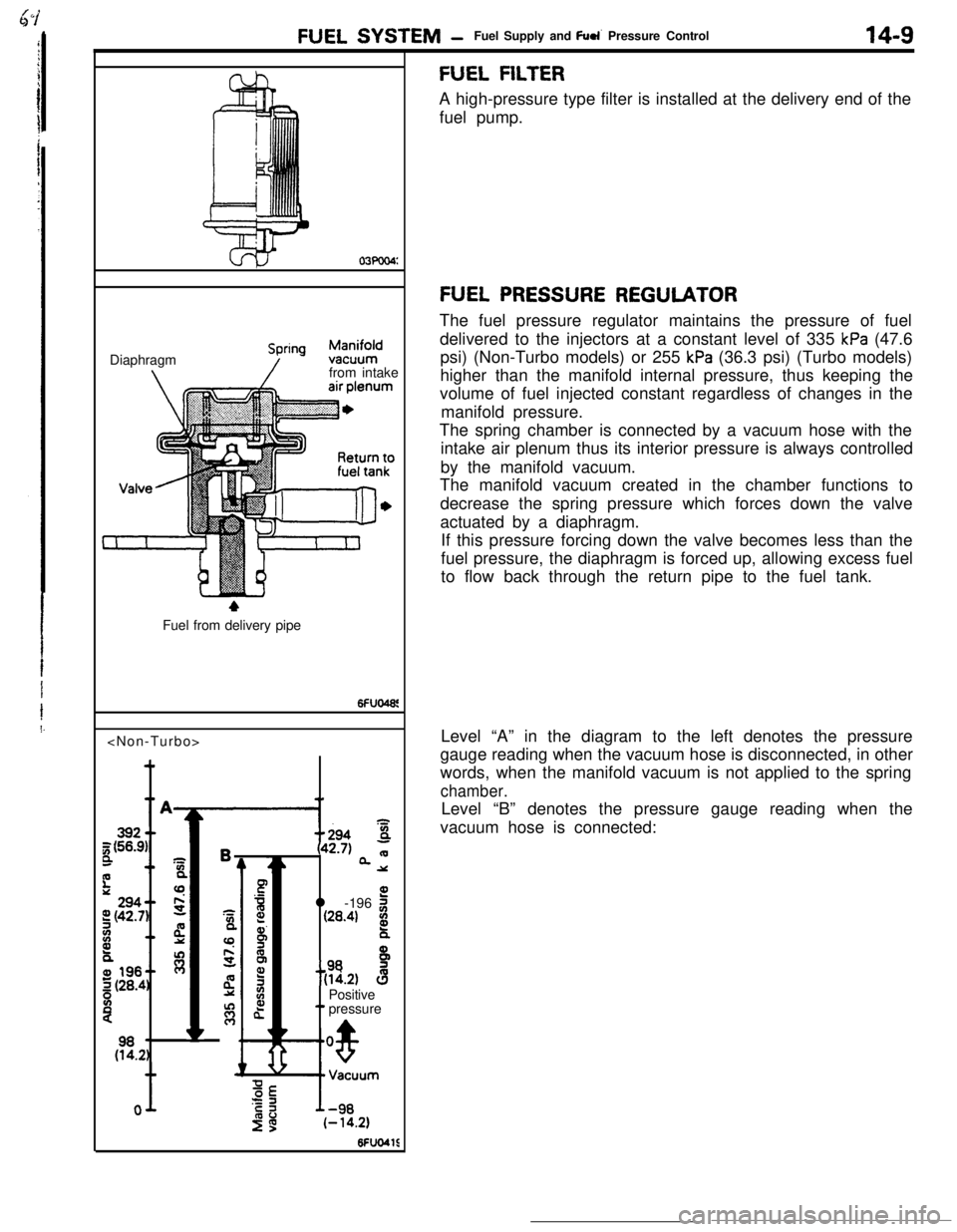
FUEL PRESSURE REGULATORThe fuel pressure regulator maintains the pressure of fuel
delivered to the injectors at a constant level of 335
kPa (47.6
psi) (Non-Turbo models) or 255
kPa (36.3 psi) (Turbo models)
higher than the manifold internal pressure, thus keeping the
volume of fuel injected constant regardless of changes in the
manifold pressure.
The spring chamber is connected by a vacuum hose with the
intake air plenum thus its interior pressure is always controlled
by the manifold vacuum.
The manifold vacuum created in the chamber functions to
decrease the spring pressure which forces down the valve
actuated by a diaphragm.
If this pressure forcing down the valve becomes less than the
fuel pressure, the diaphragm is forced up, allowing excess fuel
to flow back through the return pipe to the fuel tank.
Level “A” in the diagram to the left denotes the pressure
gauge reading when the vacuum hose is disconnected, in other
words, when the manifold vacuum is not applied to the spring
chamber.Level “B” denotes the pressure gauge reading when the
vacuum hose is connected:
Page 123 of 391
FUEL SYSTEM -Fuel Supply and Fuel Pressure Control
FUEL-PRESSURE CONTROL VALVE
14-11To fuel
-
Fuel-pressureregulatorFuel-pressurecontrol valve
Intake-airEnginecontrol
unit
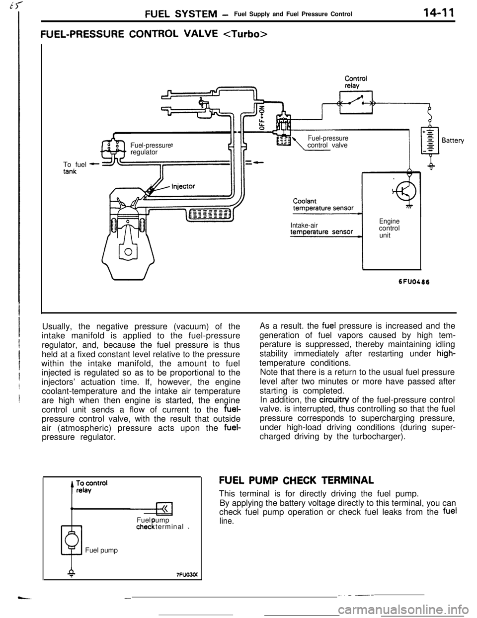
Usually, the negative pressure (vacuum) of the
intake manifold is applied to the fuel-pressure
regulator, and, because the fuel pressure is thus
held at a fixed constant level relative to the pressure
within the intake manifold, the amount to fuel
injected is regulated so as to be proportional to the
injectors’ actuation time. If, however, the engine
coolant-temperature and the intake air temperature
are high when then engine is started, the engine
control unit sends a flow of current to the fuel-
pressure control valve, with the result that outside
air (atmospheric) pressure acts upon the fuel-
pressure regulator.
0Fuel ump
1chec terminal 1!Fuel pumpAs a result. the
fuel pressure is increased and the
generation of fuel vapors caused by high tem-
perature is suppressed, thereby maintaining idling
stability immediately after restarting under
high-temperature conditions.
Note that there is a return to the usual fuel pressure
level after two minutes or more have passed after
starting is completed.
In addition, the circuitry of the fuel-pressure control
valve. is interrupted, thus controlling so that the fuel
pressure corresponds to supercharging pressure,
under high-load driving conditions (during super-
charged driving by the turbocharger).
FU,EL PUMP CHECK TERMINAL
This terminal is for directly driving the fuel pump.
By applying the battery voltage directly to this terminal, you can
check fuel pump operation or check fuel leaks from the
fuel
line.
__. - ---