differential MITSUBISHI ECLIPSE 1990 User Guide
[x] Cancel search | Manufacturer: MITSUBISHI, Model Year: 1990, Model line: ECLIPSE, Model: MITSUBISHI ECLIPSE 1990Pages: 391, PDF Size: 15.27 MB
Page 120 of 391
14-8
rFUEL SYSTEM
-Fuel Supply and Fuel Pressure Control
FUEL PUMP
This fuel pump is known as the in-tank type becauseit is located within the fuel tank itself, surrounded by
the fuel. For this reason, the pump operation noise
is well insulated, and it has excellent resistance to
vapor-locks.This type of pump is also called the “wet type”
because even its internal parts are in contact with
the fuel. With a construction that is the unification of
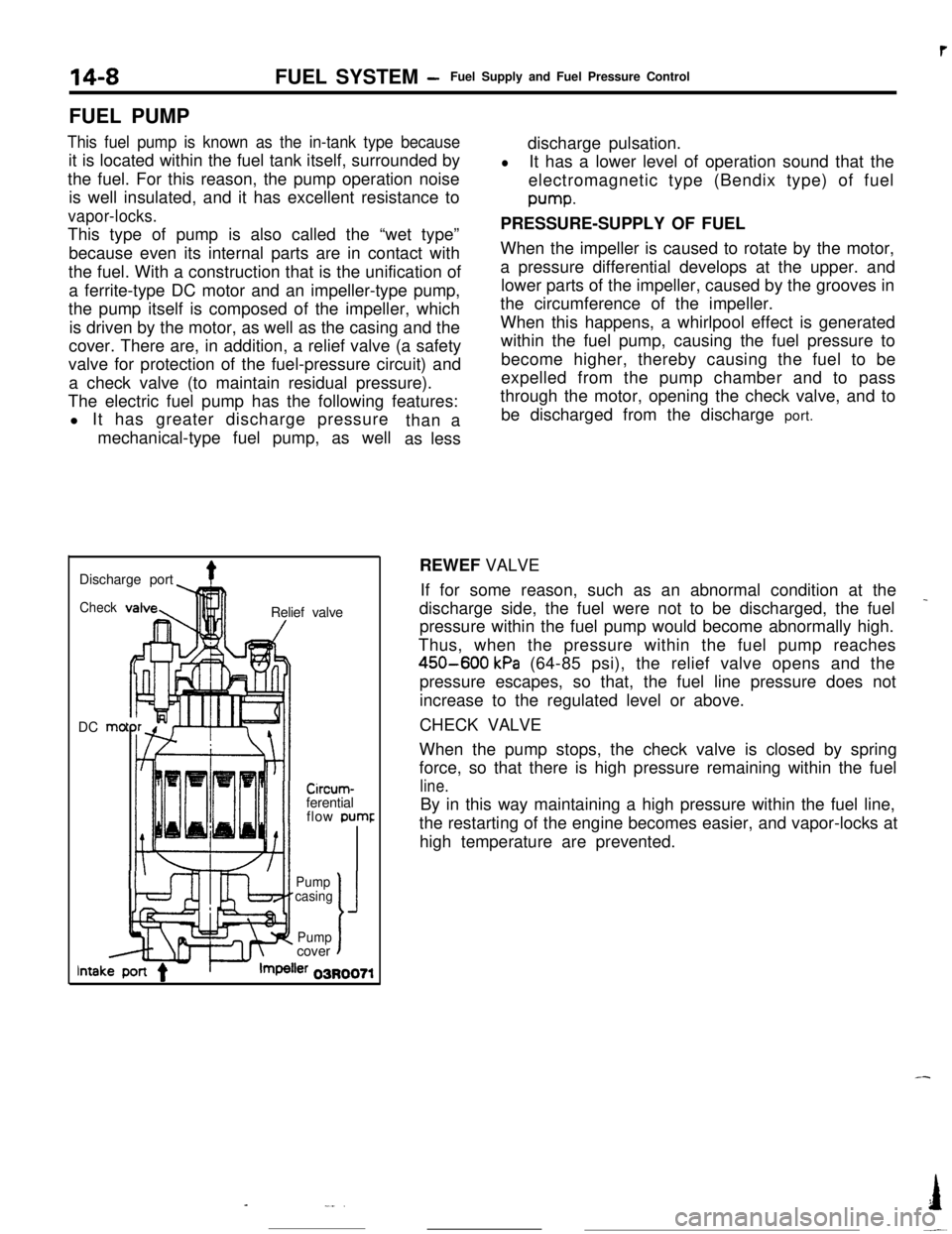
a ferrite-type DC motor and an impeller-type pump,
the pump itself is composed of the impeller, which
is driven by the motor, as well as the casing and the
cover. There are, in addition, a relief valve (a safety
valve for protection of the fuel-pressure circuit) and
a check valve (to maintain residual pressure).
The electric fuel pump has the following features:
l It has greater discharge pressure
mechanical-type fuel pump, as wellthan a
as lessdischarge pulsation.
lIt has a lower level of operation sound that the
electromagnetic type (Bendix type) of fuelpump.
PRESSURE-SUPPLY OF FUEL
When the impeller is caused to rotate by the motor,
a pressure differential develops at the upper. and
lower parts of the impeller, caused by the grooves in
the circumference of the impeller.
When this happens, a whirlpool effect is generated
within the fuel pump, causing the fuel pressure to
become higher, thereby causing the fuel to be
expelled from the pump chamber and to pass
through the motor, opening the check valve, and to
be discharged from the discharge port.
Discharge port
4Check!nRelief valve
DC mo
-lllll1 I/
Circum-ferential
flow pumr
II’ f-Pump
casing
J
Pumpcovert
lntakler 03R0071REWEF VALVE
If for some reason, such as an abnormal condition at the
_discharge side, the fuel were not to be discharged, the fuel
pressure within the fuel pump would become abnormally high.
Thus, when the pressure within the fuel pump reaches
450-600 kPa (64-85 psi), the relief valve opens and the
pressure escapes, so that, the fuel line pressure does not
increase to the regulated level or above.
CHECK VALVE
When the pump stops, the check valve is closed by spring
force, so that there is high pressure remaining within the fuel
line.By in this way maintaining a high pressure within the fuel line,
the restarting of the engine becomes easier, and vapor-locks at
high temperature are prevented.
-
-_..I
-~
Page 206 of 391
-
REAR SUSPENSION -Double Wishbone Suspension17-13
Member supponbushingI
12AOO5
Upper arm
Link diagram of ordinarydouble wishbone suspension system
5. The suspension crossmember is mounted with the mem-
ber support bushing on the body. The input from the wheel
is first damped by the trailing arm and the bushings of the
lateral arms. It is then further damped by the member
support bushing. This dual anti-vibration construction
provides low vibration and low noise.
In addition, mounting of the differential carrier on this
crossmember decreases the natural frequency of the
crossmember, further damping vibrations.
The lower natural frequency of the crossmember allows
harder adjustment of the support bushing so that the
tendency toward oversteering of the suspension due to
side force, occurring during cornering can be reduced. This,
combined with understeering tendency by middle joint
.displacement described in (3) above, results in totally slight
understeering tendency.
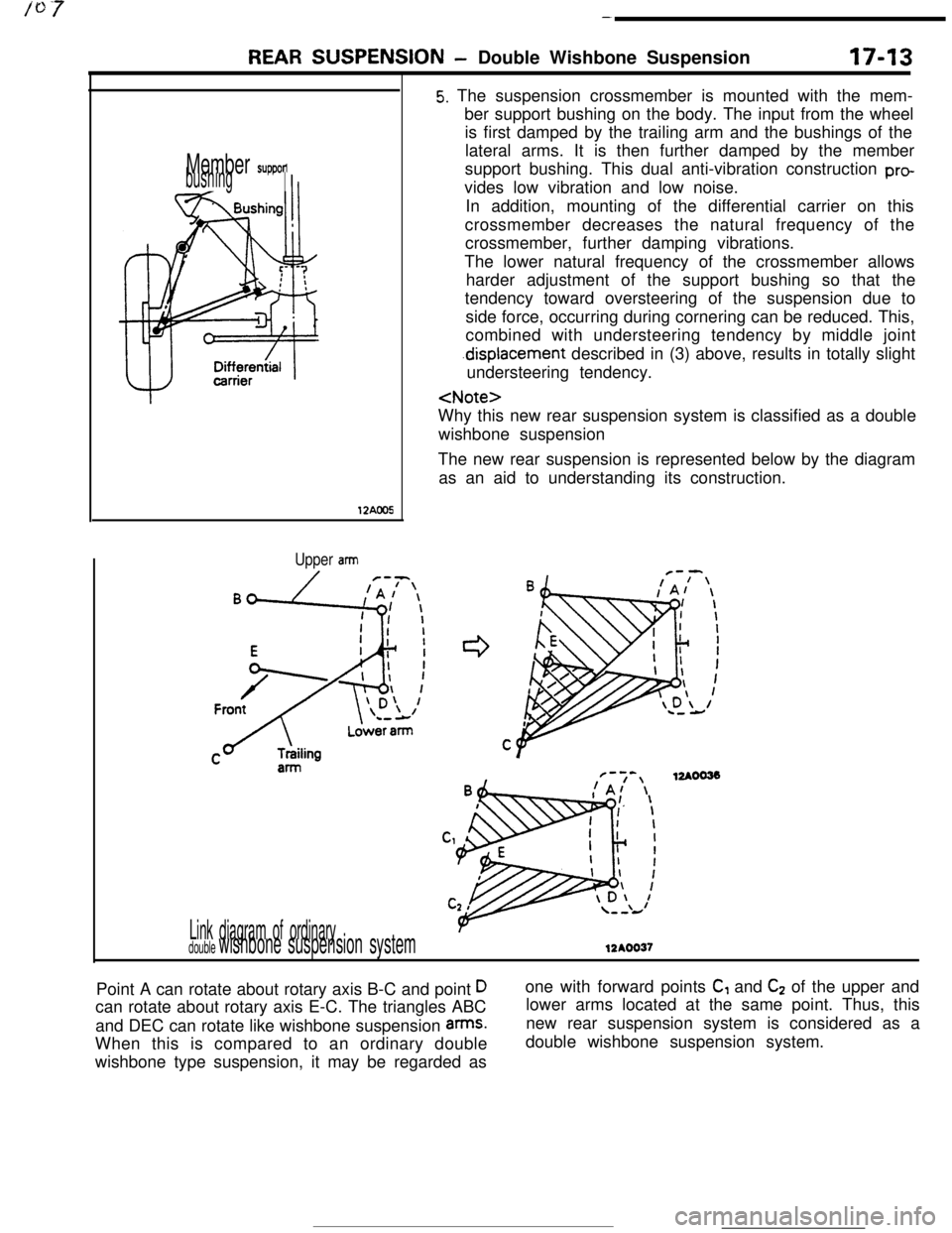
wishbone suspension
The new rear suspension is represented below by the diagram
as an aid to understanding its construction.
F-7-,12AOO33!A/ \
12AOO37Point A can rotate about rotary axis B-C and point
Dcan rotate about rotary axis E-C. The triangles ABC
and DEC can rotate like wishbone suspension
arms.When this is compared to an ordinary double
wishbone type suspension, it may be regarded asone with forward points
C, and C2 of the upper and
lower arms located at the same point. Thus, this
new rear suspension system is considered as a
double wishbone suspension system.
Page 228 of 391
MANUAL TRANSAXLE <2WD> - General InformationF5M33
Clutch housing
Bearing retainer
\1st speedgear
2nd speed gear
I3rd speed gear
3rd-4th speed synchronizer assembly
4th speed gear
I5th speed gear
1 st-2nd
speedsynchro-
nizerassembly5th speed
synchronizer
assembly
- Rear Cover
. Reyerse gear
now-prevention
device
-5th speed inter
mediate gear
Intermediate
Differential drive gear
SpacerDrain plug
gear
Page 230 of 391
MANUAL TRANSAXLE <4WD> - General Information
MANUAL TRANSAXLE <4WD>
GENERAL INFORMATION
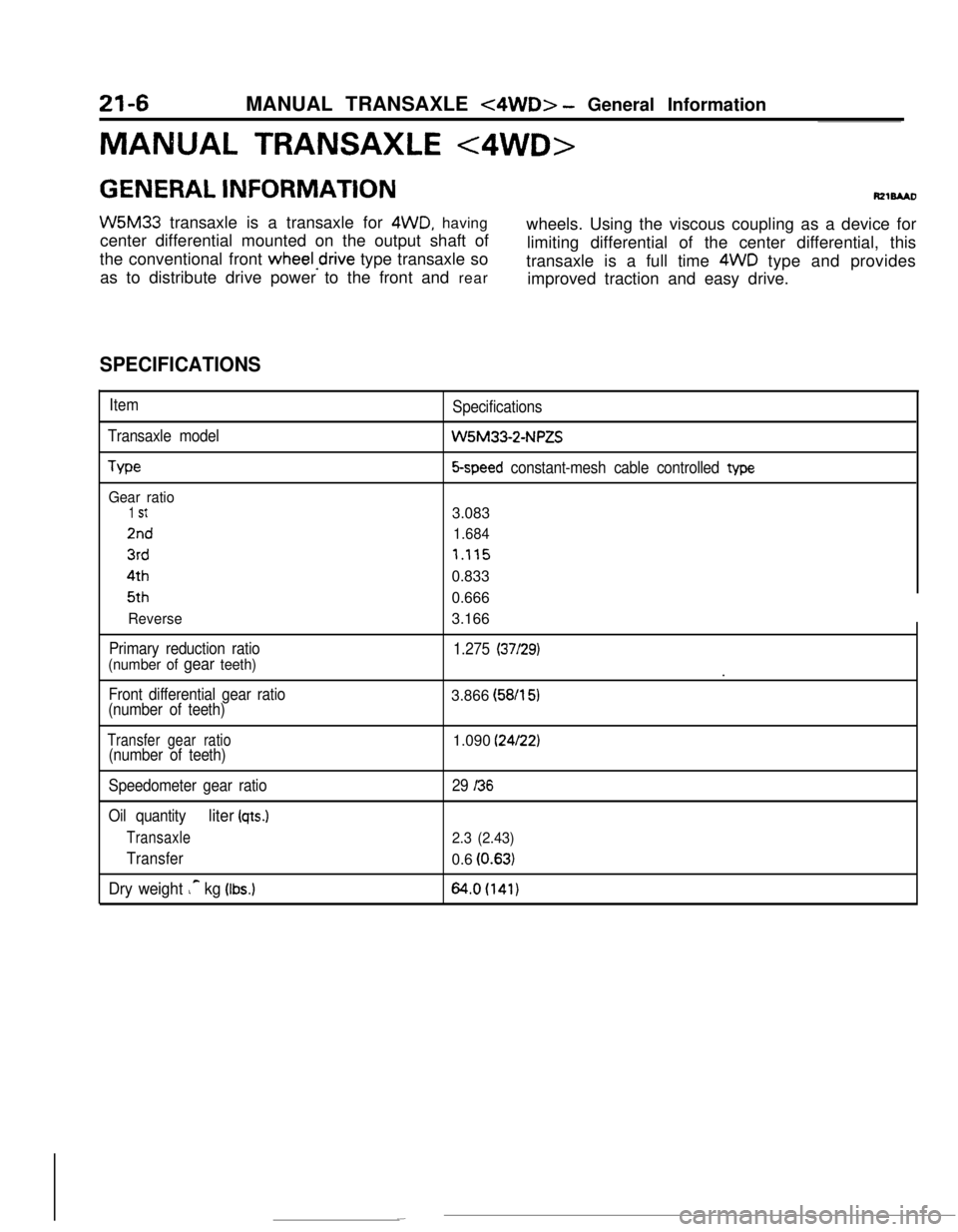
W5M33 transaxle is a transaxle for 4WD, having
center differential mounted on the output shaft ofwheels. Using the viscous coupling as a device for
the conventional front
wheeledrive type transaxle solimiting differential of the center differential, this
as to distribute drive power to the front and reartransaxle is a full time 4WD type and provides
improved traction and easy drive.
SPECIFICATIONS
Item
Transaxle model
We
Gear ratio
1 St
2nd
3rd4th5th
Reverse
Primary reduction ratio
(number of gear teeth)
Front differential gear ratio
(number of teeth)Specifications
W5M33-2-NPZS
5-speed constant-mesh cable controlled type3.083
1.684
7.1150.833
0.666
3.166
1.275 (37/29).
3.866 (58/l
51
Transfer gear ratio(number of teeth)1.090 (24/22)
Speedometer gear ratio
Oil quantity
liter (qts.)
Transaxle
Transfer
Dry weight ic kg (Ibs.)
29 I36
2.3 (2.43)0.6
(0.63)
64.0(141)
Page 231 of 391
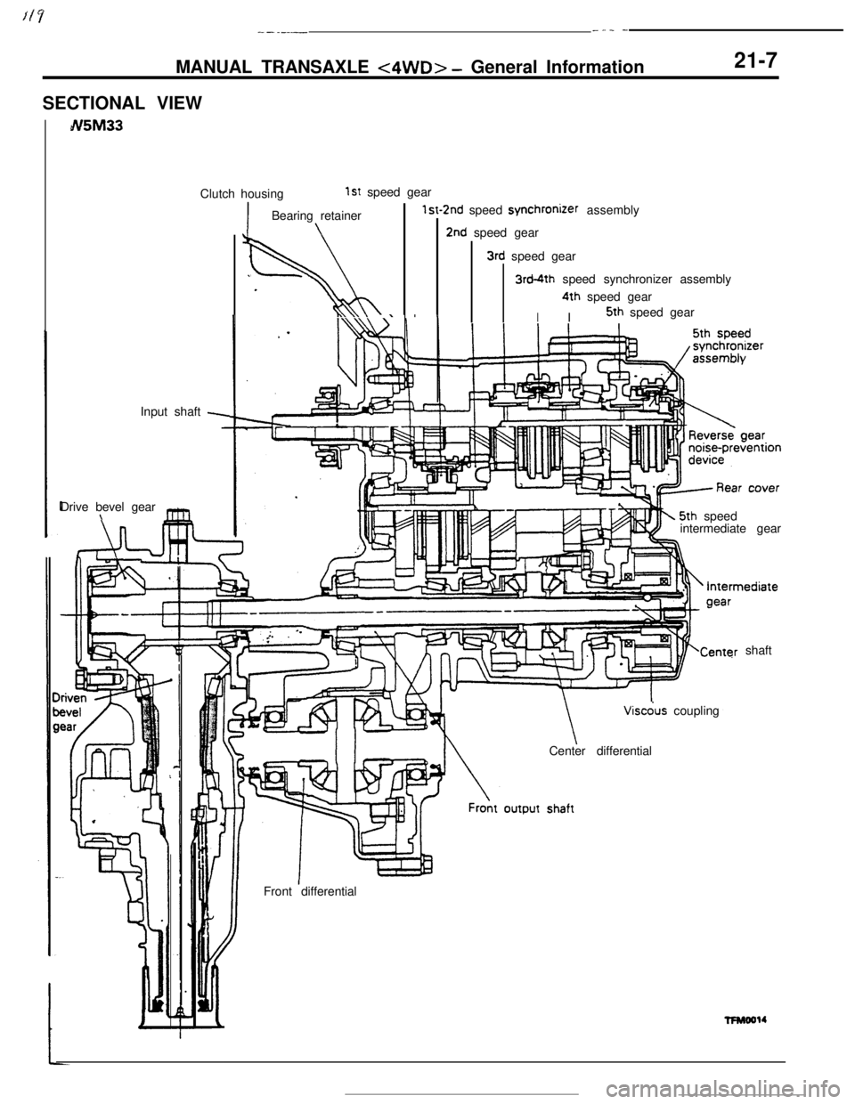
--.-.--_ _ _-MANUAL TRANSAXLE
<4WD> - General Information
SECTIONAL VIEWN5M3321-7Clutch housing
1st speed gear
Input shaft
-Drive bevel gear
\r
l!
.IBearing retainer\
St-1
w
.
I,..\\I \ I I
2nd speed synchronizer assembly
2nd speed gear
3rd speed gear
3rd-4th speed synchronizer assembly
I4th speed gear
I5th speed gear
5th speed
intermediate gear
shaft
Center differential
Front differentialViscdus coupling
wMool4
Page 232 of 391
_.c.
21-8MANUAL TRANSAXLE <4WD> - General Information4WD SYSTEM
Viscous couplingCenter differential
cous coupling
kCenth differential
I
IFro& differential
Rear differential
I
I
I [[lll,i, ‘- h-
1 p’f’ ,* , l/i\
/IViscous couplingL
(Option)
3
2210105CONSTRUCTION
OF THE 4WD SYSTEM
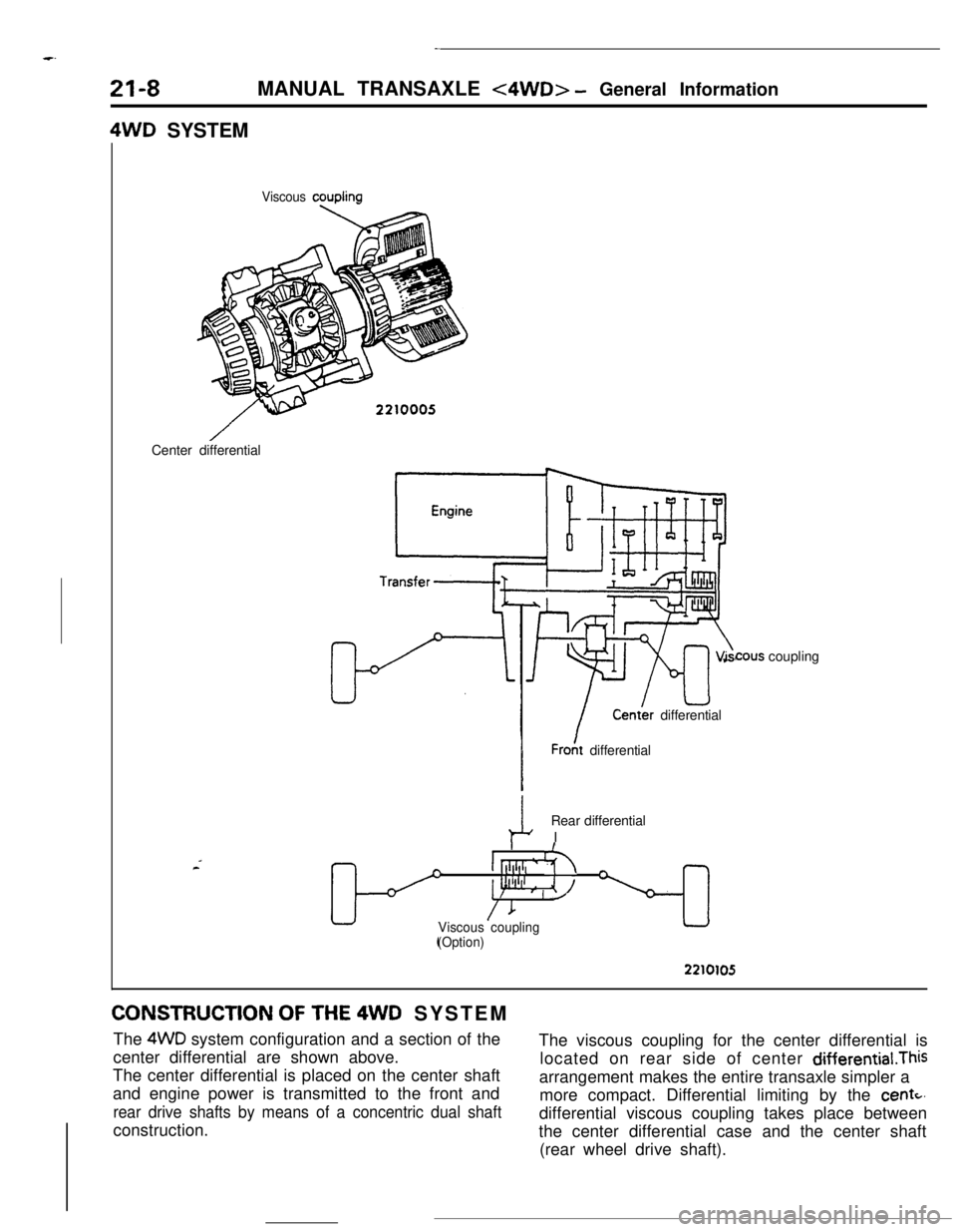
The 4WD system configuration and a section of the
center differential are shown above.The viscous coupling for the center differential is
The center differential is placed on the center shaftlocated on rear side of center differential.This
and engine power is transmitted to the front andarrangement makes the entire transaxle simpler a
rear drive shafts by means of a concentric dual shaftmore compact. Differential limiting by the
centc,construction.differential viscous coupling takes place between
the center differential case and the center shaft
(rear wheel drive shaft).
Page 233 of 391
-MANUAL TRANSAXLE
<4WD> - General information
21-9
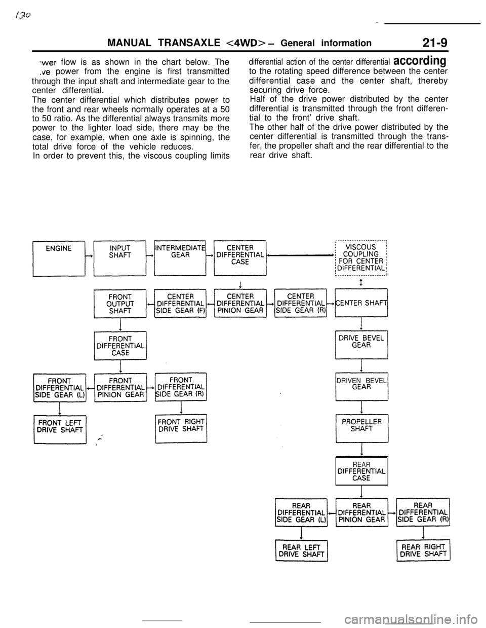
wer flow is as shown in the chart below. The
.ire power from the engine is first transmitted
through the input shaft and intermediate gear to the
center differential.
The center differential which distributes power to
the front and rear wheels normally operates at a 50
to 50 ratio. As the differential always transmits more
power to the lighter load side, there may be the
case, for example, when one axle is spinning, the
total drive force of the vehicle reduces.
In order to prevent this, the viscous coupling limits
differential action of the center differential accordingto the rotating speed difference between the center
differential case and the center shaft, thereby
securing drive force.
Half of the drive power distributed by the center
differential is transmitted through the front differen-
tial to the front’ drive shaft.
The other half of the drive power distributed by the
center differential is transmitted through the trans-
fer, the propeller shaft and the rear differential to the
rear drive shaft.
DRIVEN BEVEL
REARDIFF~;MfTIAL
,
Page 234 of 391
21-10MANUAL TRANSAXLE <4WD> - General Information4WD SYSTEM OPERATION
Conventional 4WD systems (direct-coupled
4WD,or center differential type 4WDl have their own
merits and demerits; they rely on manual operation
(switching between 4WD and 2WD modes, center
differential locking) to cope with their demerits.
With this new 4WD system, the viscous coupling
built in the center differential automatically performssuch operations used to be made manually. The
driver can participate with the merits of 4WD at alltimes.The operation of the differential and the
viscous
coupling under representative conditions
are described in the following section.
I
Reardifferential
Center
differential
U differential
Viscous AuDk?TFNOO5’difference
ce271010i
TFMMYTFMMY
0
Turningdirection
ITFMOO!X
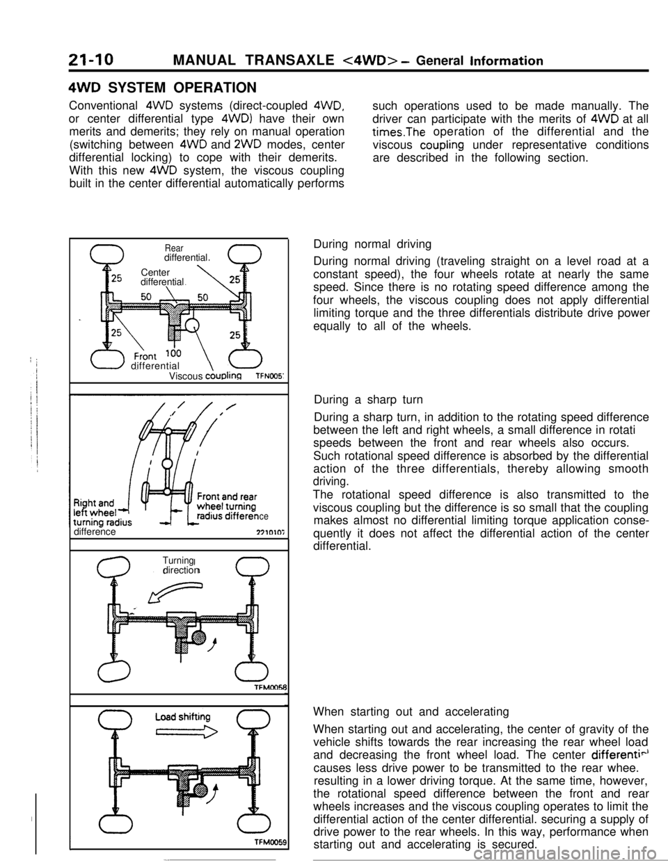
-.During normal driving
During normal driving (traveling straight on a level road at a
constant speed), the four wheels rotate at nearly the same
speed. Since there is no rotating speed difference among the
four wheels, the viscous coupling does not apply differential
limiting torque and the three differentials distribute drive power
equally to all of the wheels.
During a sharp turn
During a sharp turn, in addition to the rotating speed difference
between the left and right wheels, a small difference in rotati
speeds between the front and rear wheels also occurs.
Such rotational speed difference is absorbed by the differential
action of the three differentials, thereby allowing smooth
driving.The rotational speed difference is also transmitted to the
viscous coupling but the difference is so small that the coupling
makes almost no differential limiting torque application conse-
quently it does not affect the differential action of the center
differential.
When starting out and accelerating
When starting out and accelerating, the center of gravity of the
vehicle shifts towards the rear increasing the rear wheel load
and decreasing the front wheel load. The center
differenti”causes less drive power to be transmitted to the rear whee.
resulting in a lower driving torque. At the same time, however,
the rotational speed difference between the front and rear
wheels increases and the viscous coupling operates to limit the
differential action of the center differential. securing a supply of
drive power to the rear wheels. In this way, performance when
starting out and accelerating is secured.
Page 235 of 391
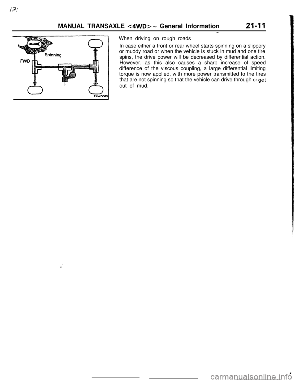
MANUAL TRANSAXLE <4WD> - General Information21-I 1When driving on rough roads. . .In case either a front or rear wheel starts spinning on a slippery
or muddy road or when the vehicle is stuck in mud and one tire
spins, the drive power will be decreased by differential action.
However, as this also causes a sharp increase of speed
difference of the viscous coupling, a large differential limiting
torque is now applied, with more power transmitted to the tires
that are not spinning so that the vehicle can drive through or
getout of mud.A
Page 236 of 391
21-12MANUAL TRANSAXLE <4WD> - Viscous Coupling (VCU)
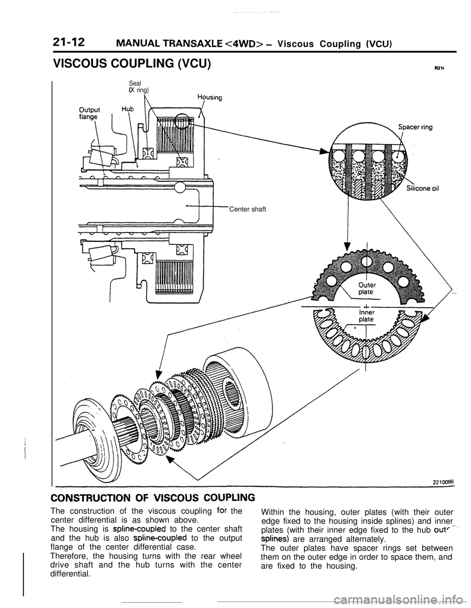
VISCOUS COUPLING (VCU)
RZlL
Seal(X ring)Center shaftCONSTRUCTION
OF VISCOUS COUPLINGThe construction of the viscous coupling
fck the
Within the housing, outer plates (with their outer
center differential is as shown above.
edge fixed to the housing inside splines) and inner
The housing is splinecoupled to the center shaft
plates (with their inner edge fixed to the hub
outF--and the hub is also
spline-coupled to the outputsplines) are arranged alternately.
flange of the center differential case.
The outer plates have spacer rings set between
Therefore, the housing turns with the rear wheel
them on the outer edge in order to space them, and
drive shaft and the hub turns with the center
are fixed to the housing.
differential.