differential MITSUBISHI ECLIPSE 1990 Owner's Manual
[x] Cancel search | Manufacturer: MITSUBISHI, Model Year: 1990, Model line: ECLIPSE, Model: MITSUBISHI ECLIPSE 1990Pages: 391, PDF Size: 15.27 MB
Page 237 of 391

MANUAL TRANSAXLE <4WD> - Viscous Coupling .(VClJ)21-13In contrast, the inner plates have no such spacer rings, and
each can slide to some extent over the hub spline shaft
between the outer plates.
The space between the housing and outer and inner plates is
filled with mixture of silicone oil and air.
Plate A
Moving atvelocity V*
OPERATION OF THE VISCOUS COUPLINGPrinciples of operation
The viscous coupling is a kind of fluid clutch that uses viscous
resistance (shear stress) of the fluid to transmit power or limit
differential action.
For this purpose, the viscous coupling uses silicone oil whose
viscosity is less variable with temperature changes.
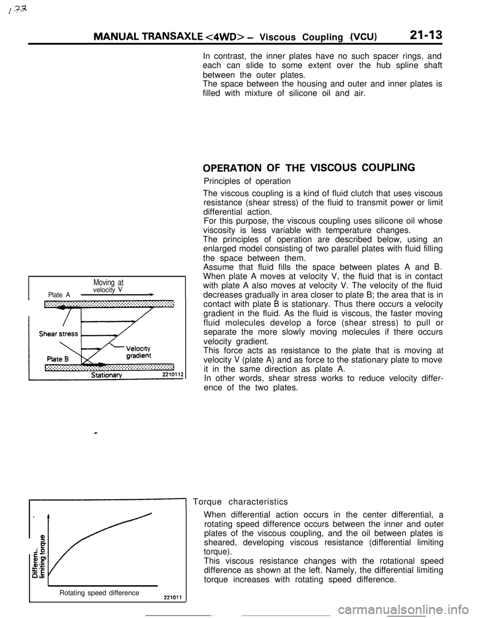
The principles of operation are described below, using an
enlarged model consisting of two parallel plates with fluid filling
the space between them.
Assume that fluid fills the space between plates A and
B.When plate A moves at velocity V, the fluid that is in contact
with plate A also moves at velocity V. The velocity of the fluid
decreases gradually in area closer to plate B; the area that is in
contact with plate
B is stationary. Thus there occurs a velocity
gradient in the fluid. As the fluid is viscous, the faster moving
fluid molecules develop a force (shear stress) to pull or
separate the more slowly moving molecules if there occurs
velocity gradient.
This force acts as resistance to the plate that is moving at
velocity
V (plate A) and as force to the stationary plate to move
it in the same direction as plate A.
In other words, shear stress works to reduce velocity differ-
ence of the two plates.
1 Torque characteristics
Rotating speed differenceWhen differential action occurs in the center differential, a
rotating speed difference occurs between the inner and outer
plates of the viscous coupling, and the oil between plates is
sheared, developing viscous resistance (differential limiting
torque).This viscous resistance changes with the rotational speed
difference as shown at the left. Namely, the differential limiting
torque increases with rotating speed difference.
Page 238 of 391

21-14MANUAL TRANSAXLE t4WD> - Viscous Coupling (VCU)
Rotating speed difference
Transmitted
torque
TemperatureII I
t
/
IIc
P&e surface‘II I
preTYl-LLL
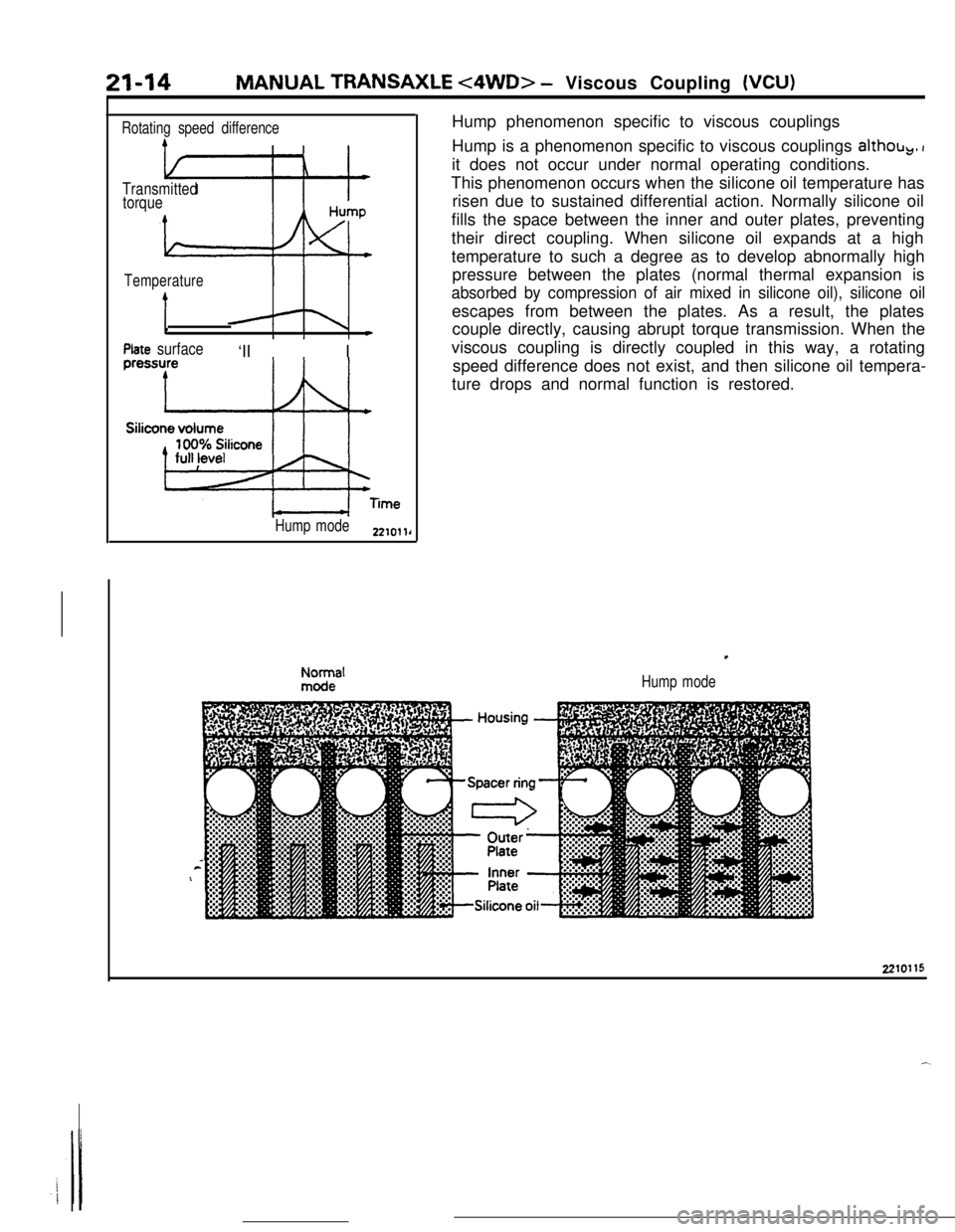
Hump mode2210llrHump phenomenon specific to viscous couplings
Hump is a phenomenon specific to viscous couplings
althob,, Iit does not occur under normal operating conditions.
This phenomenon occurs when the silicone oil temperature has
risen due to sustained differential action. Normally silicone oil
fills the space between the inner and outer plates, preventing
their direct coupling. When silicone oil expands at a high
temperature to such a degree as to develop abnormally high
pressure between the plates (normal thermal expansion is
absorbed by compression of air mixed in silicone oil), silicone oilescapes from between the plates. As a result, the plates
couple directly, causing abrupt torque transmission. When the
viscous coupling is directly coupled in this way, a rotating
speed difference does not exist, and then silicone oil tempera-
ture drops and normal function is restored.
Hump mode2210115
Page 240 of 391

_-
21-16AUTOMATIC TRANSAXLE - General InformationAUTOMATIC
TRANSAXLE
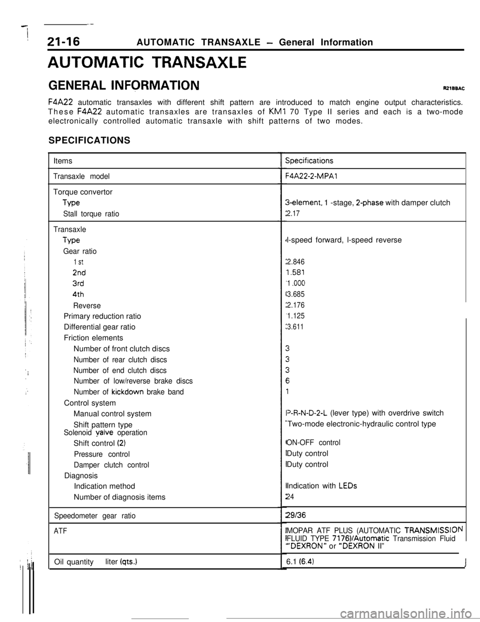
GENERAL INFQRMATIONRzlBBACF4A22 automatic transaxles with different shift pattern are introduced to match engine output characteristics.
These F4A22 automatic transaxles are transaxles of KM1 70 Type II series and each is a two-mode
electronically controlled automatic transaxle with shift patterns of two modes.
SPECIFICATIONS
Items
Transaxle modelTorque convertor
Me
Stall torque ratio
TransaxleType
Gear ratio
1 St
2nd
3rd4th
ReversePrimary reduction ratio
Differential gear ratio
Friction elements
Number of front clutch discs
Number of rear clutch discs
Number of end clutch discs
Number of low/reverse brake discs
Number of
kickdown brake bandControl system
Manual control system
Shift pattern type
Solenoid yalve operationShift control
(2)
Pressure control
Damper clutch controlDiagnosis
Indication method
Number of diagnosis items
Speedometer gear ratio
ATFOil quantityliter
(qts.)
Specifications-4A22-2-MPAl3element, 1 -stage,
2-phase with damper clutch
2.17l-speed forward, l-speed reverse
2.846
1.581
1
.ooo
3.685
2.176
1.125
3.611V&N-D-2-L (lever type) with overdrive switch
Two-mode electronic-hydraulic control type
ON-OFF controlDuty control
Duty control
Indication with
LEDs
24
29136
MOPAR ATF PLUS (AUTOMATIC TRANSMISSIOI
FLUID TYPE 7176VAutomatic Transmission Fluid“DEXRON” or “DEXRON II”
\I6.1
(6.4)J
Page 327 of 391

BODY - Main Bodv23-9
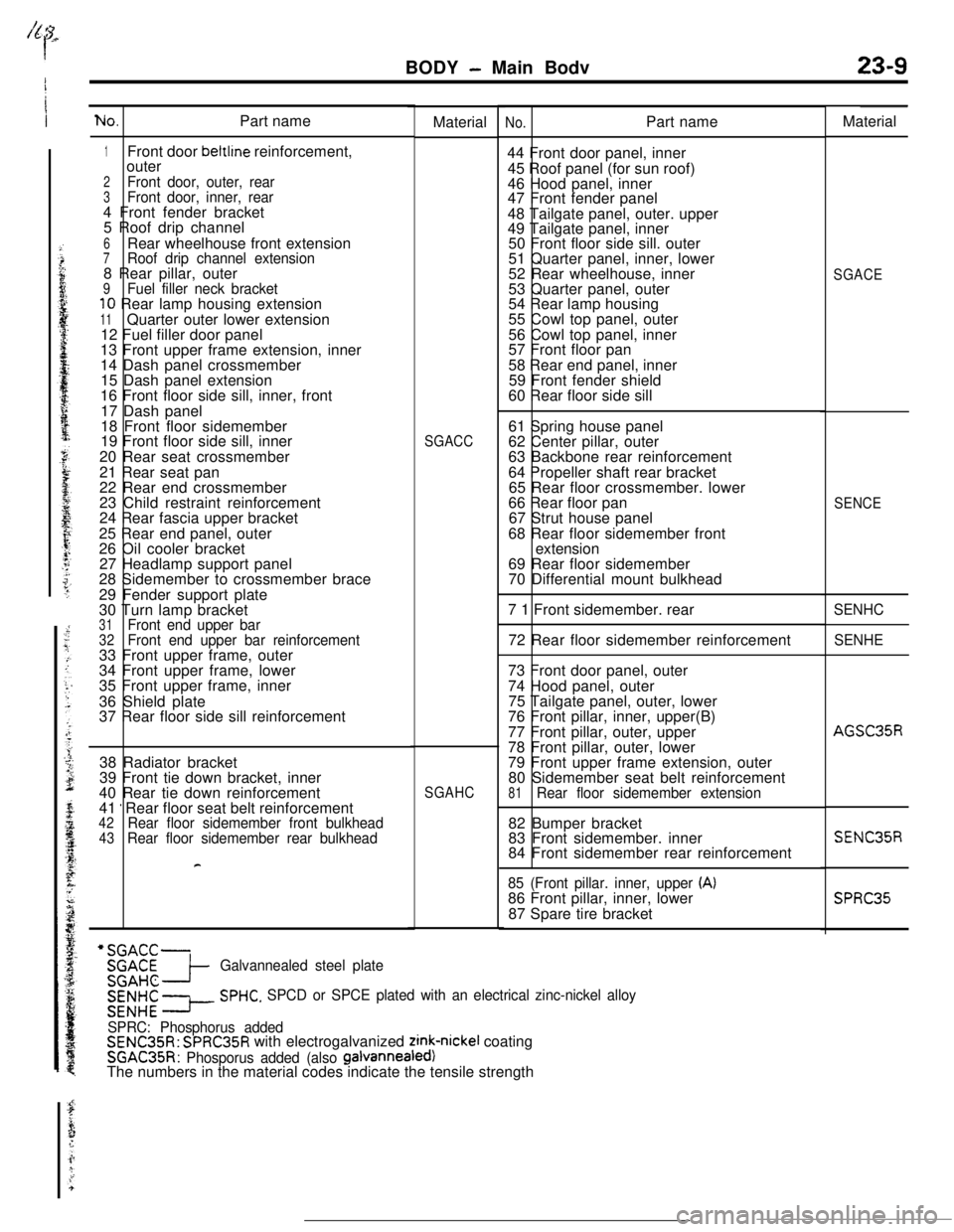
No.Part name
1Front door beltline reinforcement,
outer
2Front door, outer, rear3Front door, inner, rear4 Front fender bracket
5 Roof drip channel
6Rear wheelhouse front extension7Roof drip channel extension8 Rear pillar, outer
9Fuel filler neck bracket10 Rear lamp housing extension
11Quarter outer lower extension
12 Fuel filler door panel
13 Front upper frame extension, inner
14 Dash panel crossmember
15 Dash panel extension
16 Front floor side sill, inner, front
17 Dash panel
18 Front floor sidemember
19 Front floor side sill, inner
20 Rear seat crossmember
21 Rear seat pan
22 Rear end crossmember
23 Child restraint reinforcement
24 Rear fascia upper bracket
25 Rear end panel, outer
26 Oil cooler bracket
27 Headlamp support panel
28 Sidemember to crossmember brace
29 Fender support plate
30 Turn lamp bracket
31Front end upper bar32Front end upper bar reinforcement33 Front upper frame, outer
34 Front upper frame, lower
35 Front upper frame, inner
36 Shield plate
37 Rear floor side sill reinforcementMaterial
No.Part name
44 Front door panel, inner
45 Roof panel (for sun roof)
46 Hood panel, inner
47 Front fender panel
48 Tailgate panel, outer. upper
49 Tailgate panel, inner
50 Front floor side sill. outer
51 Quarter panel, inner, lower
52 Rear wheelhouse, inner
53 Quarter panel, outer
54 Rear lamp housing
55 Cowl top panel, outer
56 Cowl top panel, inner
57 Front floor pan
58 Rear end panel, inner
59 Front fender shield
60 Rear floor side sill
SGACC61 Spring house panel
62 Center pillar, outer
63 Backbone rear reinforcement
64 Propeller shaft rear bracket
65 Rear floor crossmember. lower
66 Rear floor pan
67 Strut house panel
68 Rear floor sidemember front
extension
69 Rear floor sidemember
70 Differential mount bulkhead
7 1 Front sidemember. rear
72 Rear floor sidemember reinforcement
38 Radiator bracket
39 Front tie down bracket, inner
40 Rear tie down reinforcement
41
’ Rear floor seat belt reinforcement42Rear floor sidemember front bulkhead43Rear floor sidemember rear bulkhead
F
SGAHC73 Front door panel, outer
74 Hood panel, outer
75 Tailgate panel, outer, lower
76 Front pillar, inner, upper(B)
77 Front pillar, outer, upper
78 Front pillar, outer, lower
79 Front upper frame extension, outer
80 Sidemember seat belt reinforcement81Rear floor sidemember extension82 Bumper bracket
83 Front sidemember. inner
84 Front sidemember rear reinforcement
85 (Front pillar. inner, upper (A)86 Front pillar, inner, lower
87 Spare tire bracket
x::-SGAHC-I-Galvannealed steel plate
E% x--
SPHC. SPCD or SPCE plated with an electrical zinc-nickel alloy
SPRC: Phosphorus added
SENC35R: SPRC35R with electrogalvanized zink-nickel coating
SGAC35R: Phosporus added (also galvanneafed)The numbers in the material codes indicate the tensile strengthMaterial
SGACE
SENCE
SENHC
SENHE
AGSC35R
SENC35R
SPRC35