cruise control MITSUBISHI ECLIPSE 1990 Owner's Manual
[x] Cancel search | Manufacturer: MITSUBISHI, Model Year: 1990, Model line: ECLIPSE, Model: MITSUBISHI ECLIPSE 1990Pages: 391, PDF Size: 15.27 MB
Page 187 of 391

_-.-, ._ u .-, 4. ::; bt-i 3,. F-7__ . ._,_ _ ” -- --.-....
FUEL SYSTEM- Auto-cruise Control System14-75INTERMEDIATE LINKS
Intermediate
iink A(accelerator pedal side)Accelerator cable
A
(accelerator pedal side)
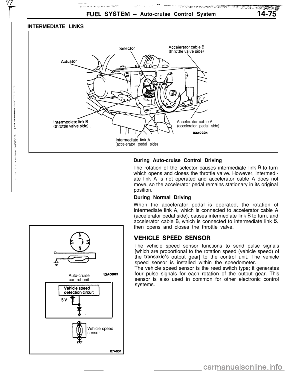
03AO224During Auto-cruise Control Driving
The rotation of the selector causes intermediate link
B to turn
which opens and closes the throttle valve. However, intermedi-
ate link A is not operated and accelerator cable A does not
move, so the accelerator pedal remains stationary in its original
position.During Normal Driving
When the accelerator pedal is operated, the rotation of
intermediate link A, which is connected to accelerator cable A
(accelerator pedal side), causes intermediate link
B to turn, and
accelerator cable
B, which is connected to intermediate link B,then opens and closes the throttle valve.
N
0
s -?s
*=Auto-cruise
control unit
13AOO62Vehicle speed
sensor07Aml
VEHICLE SPEED SENSORThe vehicle speed sensor functions to send pulse signals
[which are proportional to the rotation speed (vehicle speed) of
the transaxle’s output gear] to the control unit. The vehicle
speed sensor is installed within the speedometer.
The vehicle speed sensor is the reed switch type; it generates
four pulse signals for each rotation of the output gear. This
sensor is also used in common for other electronic control
systems.
Page 188 of 391

- -----.--..
14-76FUEL SYSTEM -Auto-cruise Control System
Ignition switch
IGI
9
RESUActuator electro-
Microcomputer
1 T 1
rn’Auto-cruise control unit
Autocruisecontrol switch
IGlMAIN
;FF -+++&Control unit
power supply
terminal voltage
03AO264NC: Normally closed
07*0040
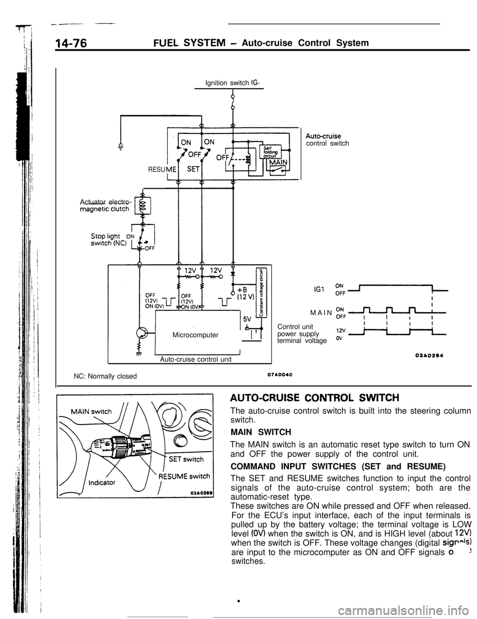
AUTO-CRUISE CONTROL SWITCH
The auto-cruise control switch is built into the steering column
switch.MAIN SWITCH
The MAIN switch is an automatic reset type switch to turn ON
and OFF the power supply of the control unit.
COMMAND INPUT SWITCHES (SET and RESUME)
The SET and RESUME switches function to input the control
signals of the auto-cruise control system; both are the
automatic-reset type.
These switches are ON while pressed and OFF when released.
For the ECU’s input interface, each of the input terminals is
pulled up by the battery voltage; the terminal voltage is LOW
level
(OV) when the switch is ON, and is HIGH level (about 12V)when the switch is OFF. These voltage changes (digital
sig*)are input to the microcomputer as ON and OFF signals
o.:
switches.
.
Page 189 of 391

-- --.-*-.e *._,_-.&” :,.>~‘c,-.y~~ 7, . . --
FUEL SYSTEM- Auto-cruise Control System14-77
(For stop light)
OFF +-ON
0N -+-OFF
(For auto-cruise control)
16RO99r4 3
12
NCNO-w-w
I/0l-COFFOFF*~ON4
321NO: Normally opened
NC: Normally closed
07AOOl:
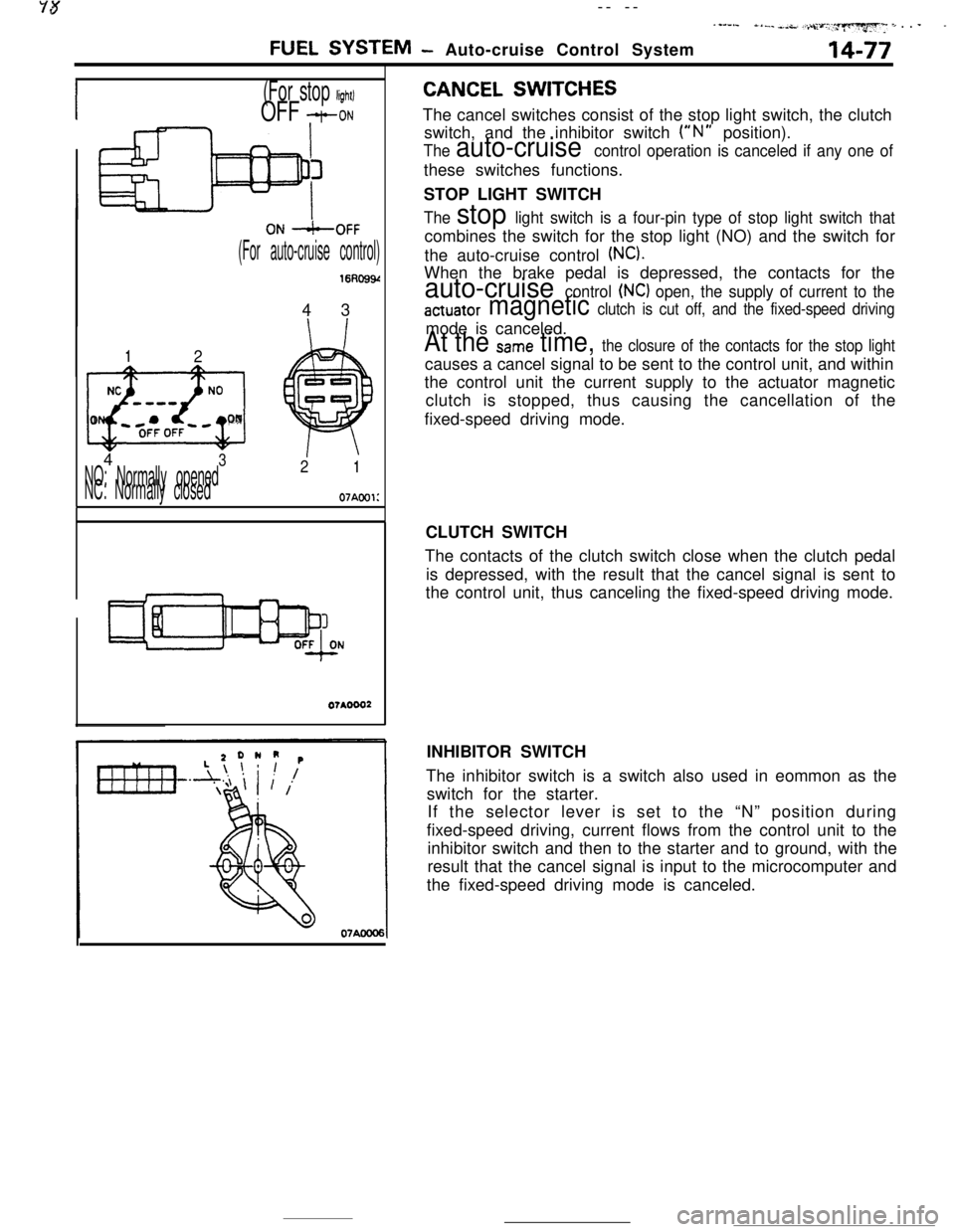
CANCEL SWITCHESThe cancel switches consist of the stop light switch, the clutch
switch, and the inhibitor switch
(“N” position).
The auto-cruise control operation is canceled if any one ofthese switches functions.
STOP LIGHT SWITCH
The stop light switch is a four-pin type of stop light switch thatcombines the switch for the stop light (NO) and the switch for
the auto-cruise control
(NC).When the brake pedal is depressed, the contacts for the
auto-cruise control (NC) open, the supply of current to the
actuator magnetic clutch is cut off, and the fixed-speed drivingmode is canceled.
At the Same time, the closure of the contacts for the stop lightcauses a cancel signal to be sent to the control unit, and within
the control unit the current supply to the actuator magnetic
clutch is stopped, thus causing the cancellation of the
fixed-speed driving mode.
CLUTCH SWITCH
The contacts of the clutch switch close when the clutch pedal
is depressed, with the result that the cancel signal is sent to
the control unit, thus canceling the fixed-speed driving mode.
INHIBITOR SWITCH
The inhibitor switch is a switch also used in eommon as the
switch for the starter.
If the selector lever is set to the “N” position during
fixed-speed driving, current flows from the control unit to the
inhibitor switch and then to the starter and to ground, with the
result that the cancel signal is input to the microcomputer and
the fixed-speed driving mode is canceled.