check oil MITSUBISHI ECLIPSE 1990 Service Manual
[x] Cancel search | Manufacturer: MITSUBISHI, Model Year: 1990, Model line: ECLIPSE, Model: MITSUBISHI ECLIPSE 1990Pages: 391, PDF Size: 15.27 MB
Page 94 of 391
CYLINDER BLOCKENGINE
- Base Engine9-9
Engine oil tocylinder
headCoolant inlet
ASilent
front
Engine oil main gallery
Silent shaft bearing,
rear
\shaft bearing,
A taw
Silenishaft bearing.
rearengine only)
6EN0246
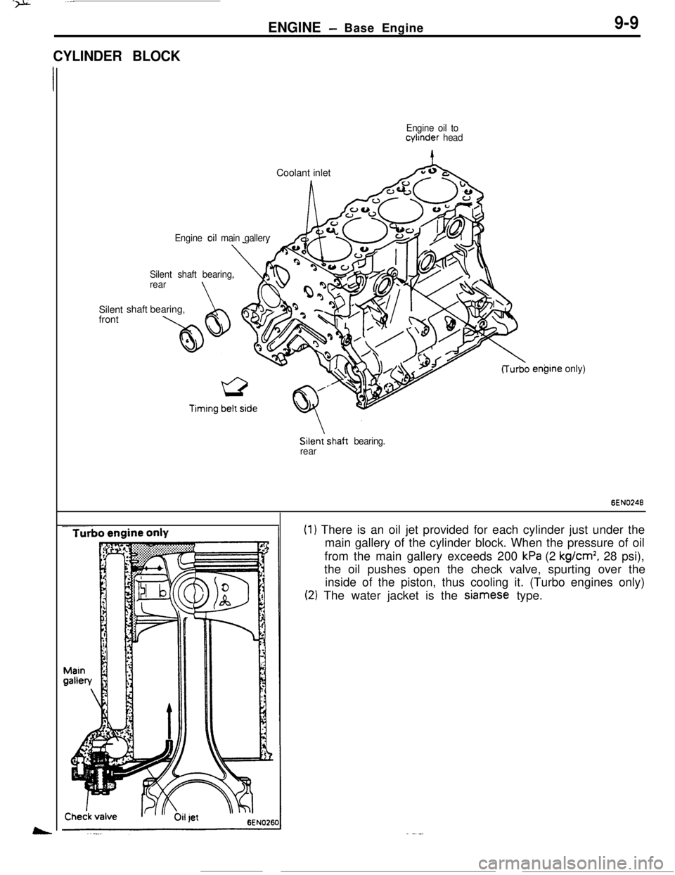
(1) There is an oil jet provided for each cylinder just under the
main gallery of the cylinder block. When the pressure of oil
from the main gallery exceeds 200
kPa (2 kg/cm’, 28 psi),
the oil pushes open the check valve, spurting over the
inside of the piston, thus cooling it. (Turbo engines only)
(2) The water jacket is the Siamese type.
Page 100 of 391
5-jENGINE- Base Engine9-15Operation of the Lash Adjuster
When the valve starts opening
/f-b
During the valve opening stroke
n
6EN0254
When the valve coiqpletesthe opening stroke
6EN0257
6EN0256
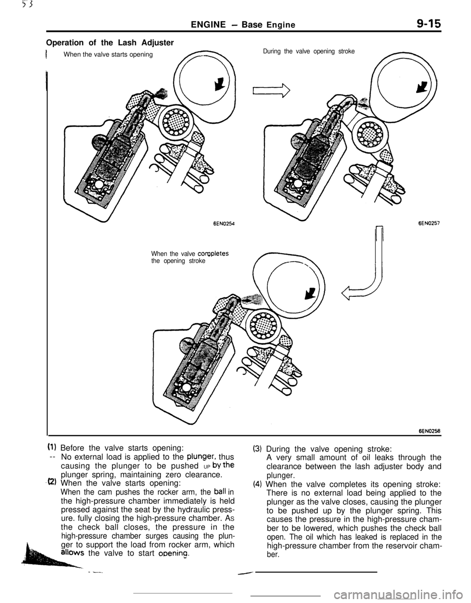
(1) Before the valve starts opening:
--
No external load is applied to the
plunger, thus
causing the plunger to be pushed UP
by theplunger spring, maintaining zero clearance.
.(2) When the valve starts opening:
When the cam pushes the rocker arm, the ball inthe high-pressure chamber immediately is held
pressed against the seat by the hydraulic press-
ure. fully closing the high-pressure chamber. AS
the check ball closes, the pressure in the
high-pressure chamber surges causing the plun-ger to support the load from rocker arm, which
.allows the valve to start ooenino.
- -__
(3) During the valve opening stroke:
A very small amount of oil leaks through the
clearance between the lash adjuster body and
plunger.
(4) When the valve completes its opening stroke:
There is no external load being applied to the
plunger as the valve closes, causing the plunger
to be pushed up by the plunger spring. This
causes the pressure in the high-pressure cham-
ber to be lowered, which pushes the check ball
open. The oil which has leaked is replaced in thehigh-pressure chamber from the reservoir cham-
ber.
-
Page 103 of 391
9-18ENGINE- Base Engine
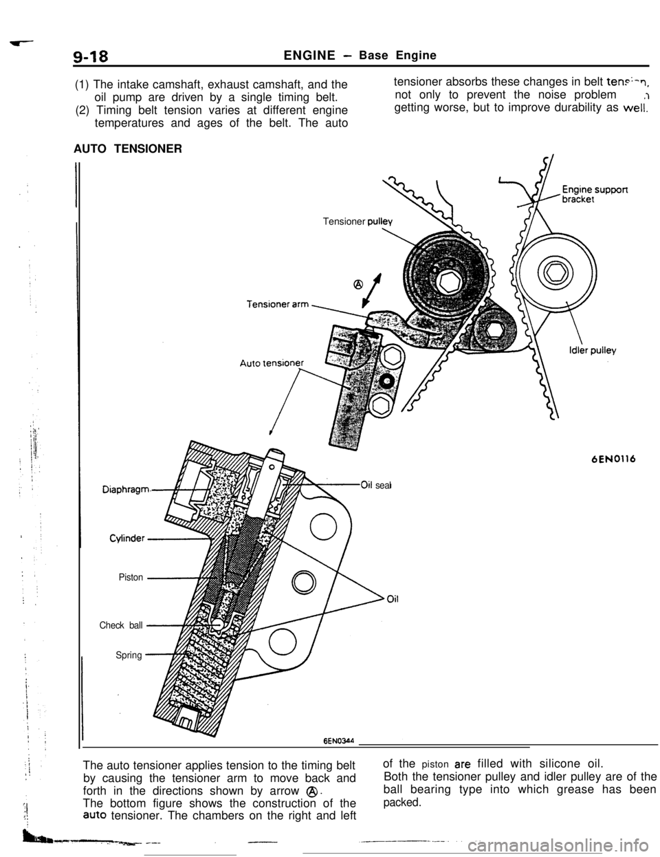
(1) The intake camshaft, exhaust camshaft, and the
oil pump are driven by a single timing belt.
(2) Timing belt tension varies at different engine
temperatures and ages of the belt. The autotensioner absorbs these changes in belt
ten+n,not only to prevent the noise problem
getting worse, but to improve durability as weli’l
AUTO TENSIONER
Piston -1
Check ball-4,
SpringTensioner
cwllev
6EN0116
LOoil seal
6ENOWThe auto tensioner applies tension to the timing belt
by causing the tensioner arm to move back and
forth in the directions shown by arrow
@I.The bottom figure shows the construction of the
aUt0 tensioner. The chambers on the right and leftof the piston
are filled with silicone oil.
Both the tensioner pulley and idler pulley are of the
ball bearing type into which grease has been
packed.
Page 104 of 391
,_-.._-~_._. I _ ‘... ----
ENGINE- Base Engine9-19
Reservoir
chamber/
Reservoir
chamber
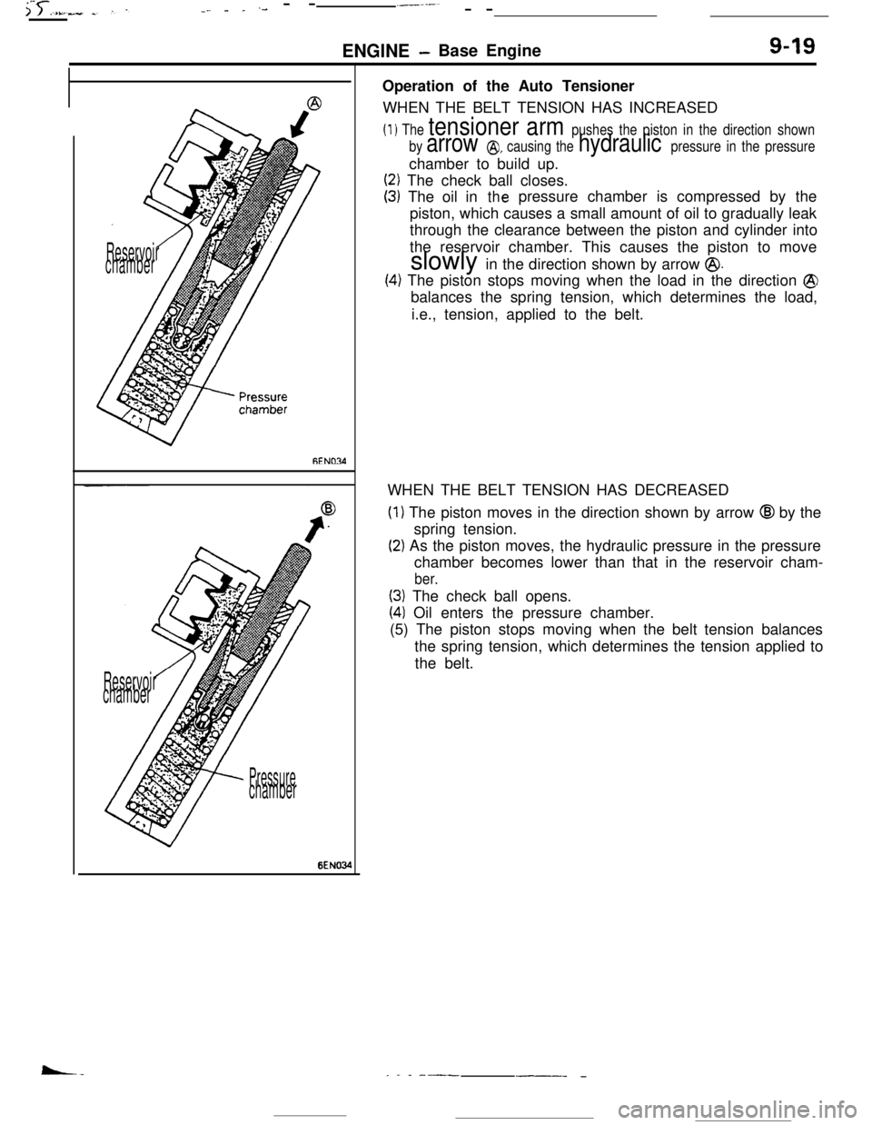
PressurechamberOperation of the Auto Tensioner
WHEN THE BELT TENSION HAS INCREASED
(1) The tensioner arm pushes the piston in the direction shown
by
arrow @, causing the hydraulic pressure in the pressurechamber to build up.
(2) The check ball closes.
(3) The oil inthepressure chamber is compressed by the
piston, which causes a small amount of oil to gradually leak
through the clearance between the piston and cylinder into
the reservoir chamber. This causes the piston to move
slowly in the direction shown by arrow
@.
(4) The piston stops moving when the load in the direction @balances the spring tension, which determines the load,
i.e., tension, applied to the belt.
WHEN THE BELT TENSION HAS DECREASED
(1) The piston moves in the direction shown by arrow @I by the
spring tension.
(2) As the piston moves, the hydraulic pressure in the pressure
chamber becomes lower than that in the reservoir cham-
ber.
(3) The check ball opens.
(41 Oil enters the pressure chamber.
(5) The piston stops moving when the belt tension balances
the spring tension, which determines the tension applied to
the belt.
_ . _ ---___- -
Page 181 of 391
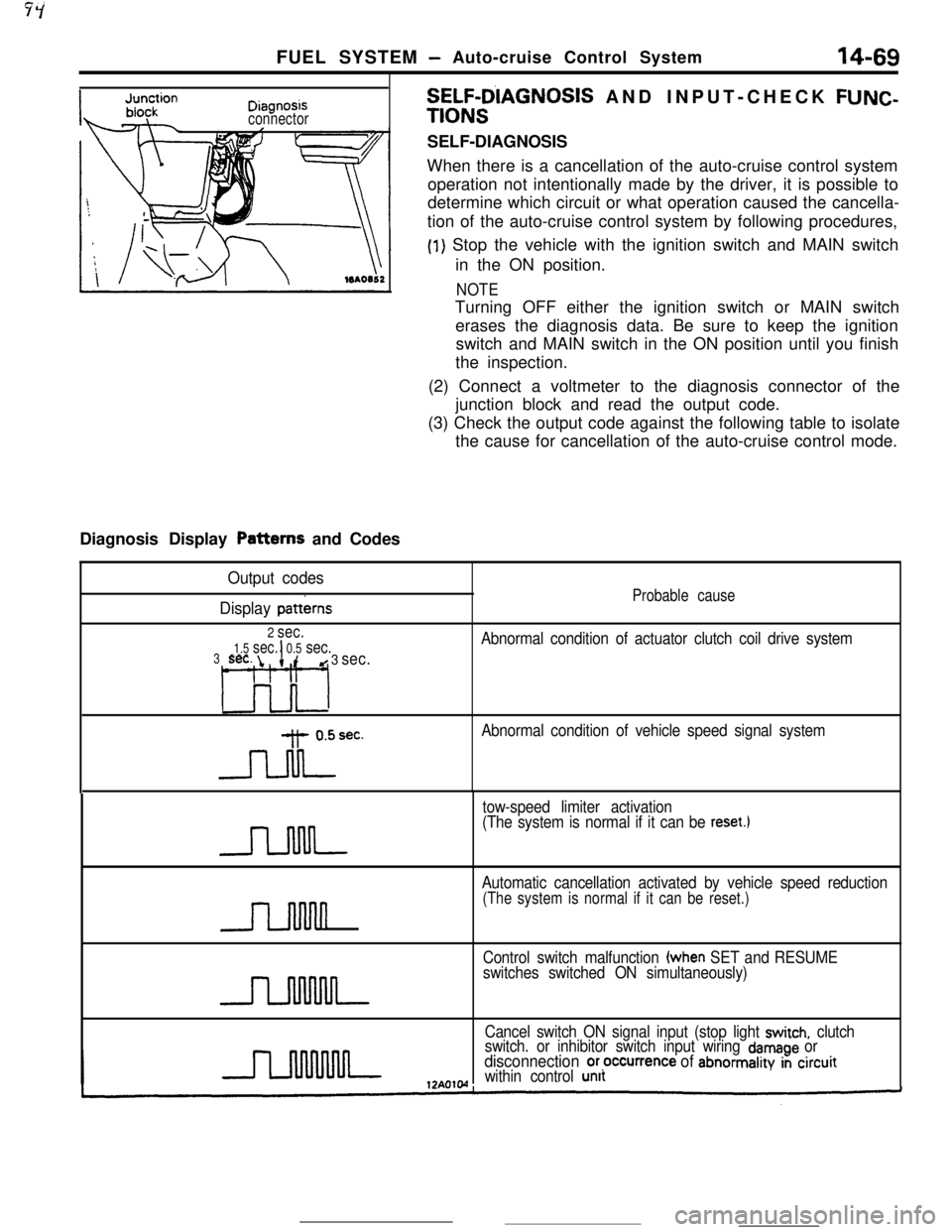
FUEL SYSTEM- Auto-cruise Control System14-69
ni2nnncisv,“y’I”“.-
connectorDiagnosis Display Patterns and Codes
SELF-D’IAGNOSIS AND INPUT-CHECK FUNC-
TIONSSELF-DIAGNOSIS
When there is a cancellation of the auto-cruise control system
operation not intentionally made by the driver, it is possible to
determine which circuit or what operation caused the cancella-
tion of the auto-cruise control system by following procedures,
(1) Stop the vehicle with the ignition switch and MAIN switch
in the ON position.
NOTETurning OFF either the ignition switch or MAIN switch
erases the diagnosis data. Be sure to keep the ignition
switch and MAIN switch in the ON position until you finish
the inspection.
(2) Connect a voltmeter to the diagnosis connector of the
junction block and read the output code.
(3) Check the output code against the following table to isolate
the cause for cancellation of the auto-cruise control mode.
Output codes
Display
patterns
2 sec.
1.5 sec.I0.5 sec.3sec. id 3 sec.
L3o-l
-Jdrec.
Probable cause
Abnormal condition of actuator clutch coil drive system
Abnormal condition of vehicle speed signal system
tow-speed limiter activation
(The system is normal if it can be
reset.1
n
Automatic cancellation activated by vehicle speed reduction
(The system is normal if it can be reset.)
Control switch malfunction (when SET and RESUME
switches switched ON simultaneously)
Cancel switch ON signal input (stop light
switch, clutch
switch. or inhibitor switch input wiring damage ordisconnection or,occurrence of abnormality in circuitwithin control unit