ignition MITSUBISHI ECLIPSE 1990 Owner's Manual
[x] Cancel search | Manufacturer: MITSUBISHI, Model Year: 1990, Model line: ECLIPSE, Model: MITSUBISHI ECLIPSE 1990Pages: 391, PDF Size: 15.27 MB
Page 118 of 391
14-6FUEL SYSTEM -Fuel Supply and Fuel Pressure Control
intake manifold/I\
Engine
Fuel
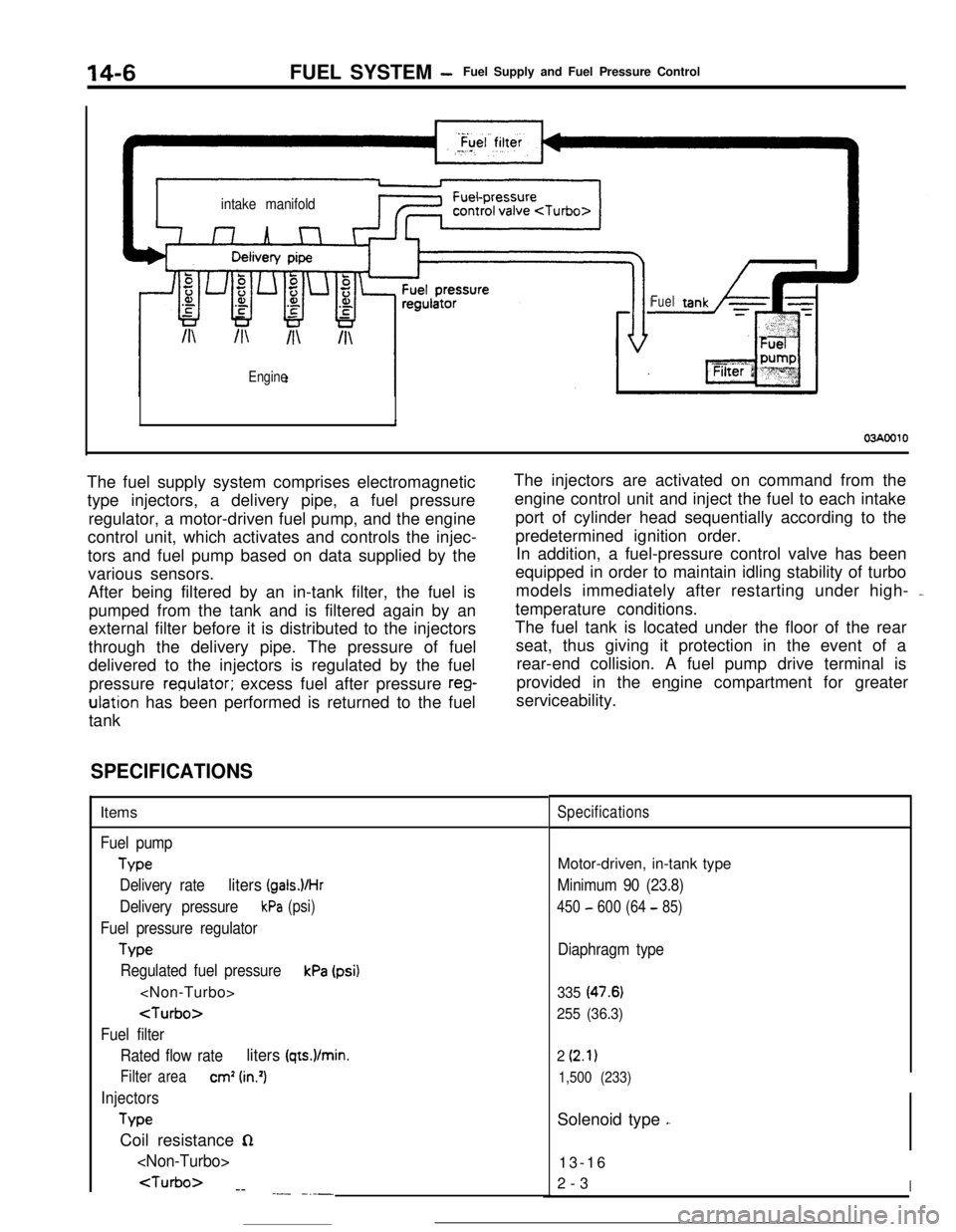
03AOOlOThe fuel supply system comprises electromagnetic
type injectors, a delivery pipe, a fuel pressure
regulator, a motor-driven fuel pump, and the engine
control unit, which activates and controls the injec-
tors and fuel pump based on data supplied by the
various sensors.
After being filtered by an in-tank filter, the fuel is
pumped from the tank and is filtered again by an
external filter before it is distributed to the injectors
through the delivery pipe. The pressure of fuel
delivered to the injectors is regulated by the fuel
pressure
reoulator; excess fuel after pressure reg-ulation has been performed is returned to the fuel
tankThe injectors are activated on command from the
engine control unit and inject the fuel to each intake
port of cylinder head sequentially according to the
predetermined ignition order.
In addition, a fuel-pressure control valve has been
equipped in order to maintain idling stability of turbo
models immediately after restarting under high- -
temperature conditions.
The fuel tank is located under the floor of the rear
seat, thus giving it protection in the event of a
rear-end collision. A fuel pump drive terminal is
provided in the engine compartment for greater
serviceability.
-
SPECIFICATIONSItems
Fuel pump
Type
Delivery rate
liters (gals.VHr
Delivery pressurekPa (psi)
Fuel pressure regulator
Tvw
Regulated fuel pressurekPa (psi)
Fuel filter
Rated flow rate
liters (qts.)/min.
Filter areacm’ (in.‘)
Injectors
TypeCoil resistance
n
--
.- -_-_
SpecificationsMotor-driven, in-tank type
Minimum 90 (23.8)
450 - 600 (64 - 85)
Diaphragm type
335 (47.6)
255 (36.3)
2
(2.1)
1,500 (233)Solenoid type
,.13-16
2-3
I
Page 126 of 391
14-14
.._~- ---.FUEL SYSTEM
- Sensors
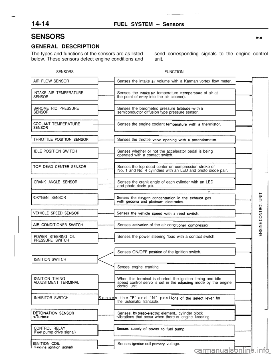
SENSORSRlUGENERAL DESCRIPTION
The types and functions of the sensors are as listedsend corresponding signals to the engine control
below. These sensors detect engine conditions and
unit.
SENSORSFUNCTION
AIR FLOW SENSOR
fSenses the intake arr volume with a Karman vortex flow meter.
INTAKE AIR TEMPERATURE
SENSORSenses the Intake air temperature (temperature of air at
the point of entry into the air cleaner).I
BAROMETRIC PRESSURE
SENSORISenses the barometric pressure faltrtude) wrth a
semiconductor diffusion type pressure sensor.
$;;OOf;T TEMPERATURESenses the engine coolant tern
THROTTLE
POSITISenses the throttle
tI
IDLE POSITION SWITCHSenses whether or not the accelerator pedal is being
operated with a contact switch.
Senses the top dead center on compression stroke of
NO. 1 and No. 4 cylinders with an LED and photo diode pair.
CRANK ANGLE SENSORSenses the crank angle of each cylinder with an LED
and photo diodepair.
T
OXYGEN SENSORSenses
actrvation of the air con
POWER STEERING OIL
PRESSURE SWITCHc-lSenses the power steering ‘load with a contact switch.
IGNITION SWITCHSenses ON/OFF
posrtion of the ignition switch.I
Senses engine cranking.
,
IGNITION TIMING
ADJUSTMENT TERMINALWhen this terminal is shorted, the ignition timing and idle
speed control servo is set in the adjustrng mode by the enginecontrol unit.
INHIBITOR SWITCHSenses the *P” and “N” positthe automatic transaxle.Senses.
by pieto-electric element,. cylinder block
vibrations that occur when there ISengineknocking.
CONTROL RELAY
(Fuel pump drive signal)
lFnorne ianitron sianal!Senses ignrtton coil prIman/ voltage.
Page 130 of 391
14-18FUEL SYSTEM - Sensors
tBAROMETRIC PRESSURE SENSOR
Barometnc rxessure sensor
EC1537
Barometncpressure sensor
Enginecontrol unit
1OFUO576
/
760 (30)Barometric pressure mmHg
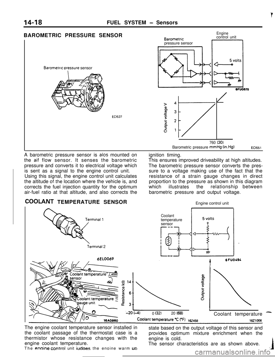
(in.Hg)EC1551A barometric pressure sensor is
alas mounted on
the
aif flow sensor. It senses the barometric
pressure and converts it to electrical voltage which
is sent as a signal to the engine control unit.
Using this signal, the engine control unit calculates
the altitude
of.the location where the vehicle is, and
corrects the fuel injection quantity for the optimum
air-fuel ratio at that altitude, and also corrects the
COOLANT TEMPERATURE SENSOR
Terminal 26EL0069ignition timing.
This ensures improved driveability at high altitudes.
The barometric pressure sensor converts the pres-
sure to a voltage making use of the fact that the
resistance of a strain gauge changes in direct
proportion to the pressure as shown in this diagram
which
illustratestherelationship between
barometric pressure and output voltage.
Engine control unit
Coolanttemperature
sensor
-a
Tg-I
h-esI
*
LizIdr
tSFUOLSL
L0 (32120 (68)Coolant temperature -The engine coolant temperature sensor installed in
the coolant passage of the thermostat case is a
thermistor whose resistance changes with the
engine coolant temperature.
The
annine control unit iudoes the enoine warm UDstate based on the output voltage of this sensor and
provides optimum mixture enrichment when the
engine is cold.
The sensor characteristics are as shown above..:I
Page 136 of 391
--
,
14-24FUEL SYSTEM - Sensors
POWER STEERING OIL PRESSURE SWITCHEngine control unit
Power steering oil
pressure switchBattery
voltage
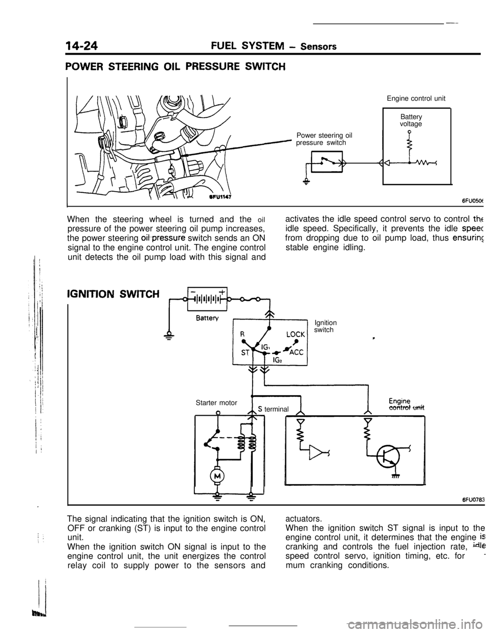
6FUO5OtIWhen the steering wheel is turned and the oil
pressure of the power steering oil pump increases,
the power steering oifpressure switch sends an ON
signal to the engine control unit. The engine control
unit detects the oil pump load with this signal andactivates the idle speed control servo to control
theidle speed. Specifically, it prevents the idle
speecfrom dropping due to oil pump load, thus
ensuringstable engine idling.IGNITION
SWITCH
1IBattery
Ignition
switch
Starter motor
aS terminalcontrol unit
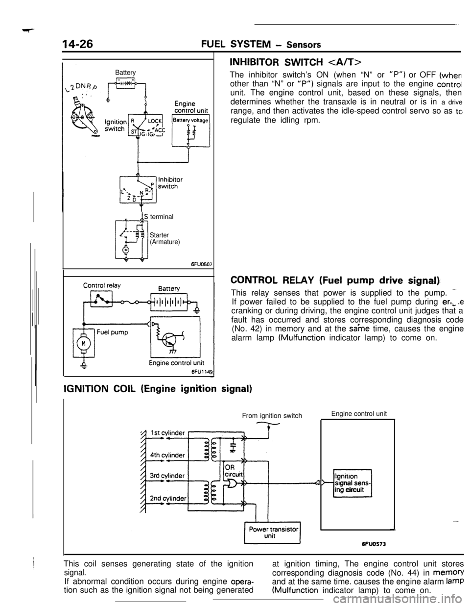
6FUO762The signal indicating that the ignition switch is ON,
OFF or cranking (ST) is input to the engine control
unit.
When the ignition switch ON signal is input to the
engine control unit, the unit energizes the control
relay coil to supply power to the sensors and
actuators.When the ignition switch ST signal is input to the
engine control unit, it determines that the engine
iscranking and controls the fuel injection rate,
despeed control servo, ignition timing, etc. for
-mum cranking conditions.
Page 137 of 391

FUEL SYSTEM - Sensors14-25Terminal for
ignition timing
adjustment
l-l6FUO51:7
W$ht(/.
Piezo-electncelements
I6FUOSlO
DetonationEngine control
unit
sensor
I-
I t i A-- >--t.--‘-3 -
wt4rlIGNITION TlMlNG ADJUSTMENT TERMINAL
This terminal
is used when adjusting the basic ignition timing or
basic idle speed.
When this terminal is shorted to ground, the engine control unit
cancels the
ignition timing control and idle speed control, and
sets the ignition
timing and idle speed control servos in their
adjusting mode.
For the basic idle speed adjustment, the diagnosis terminal is
also shorted to ground.
DETONATION SENSOR
The detonation sensor is installed at a position where it can
detect, with a high degree of precision, knocking generated at
each cylinder; it detects cylinder block vibrations caused by
knocking, and outputs voltage proportional to the magnitude of
those vibrations.
Because cylinder block vibrations caused by knocking vary
from engine to engine, the engine control unit passes this
through a frequncy filter, detecting only the knocking, thus
resulting in a spark retardation of the ignition timing that
corresponds to the strength of the knocking.
Page 138 of 391
Page 139 of 391
‘73.- .-_ _ .-__ .- -..- - .-----___. _____^. -._ __--.
FUEL SYSTEM- Enaine Control Unit14-27
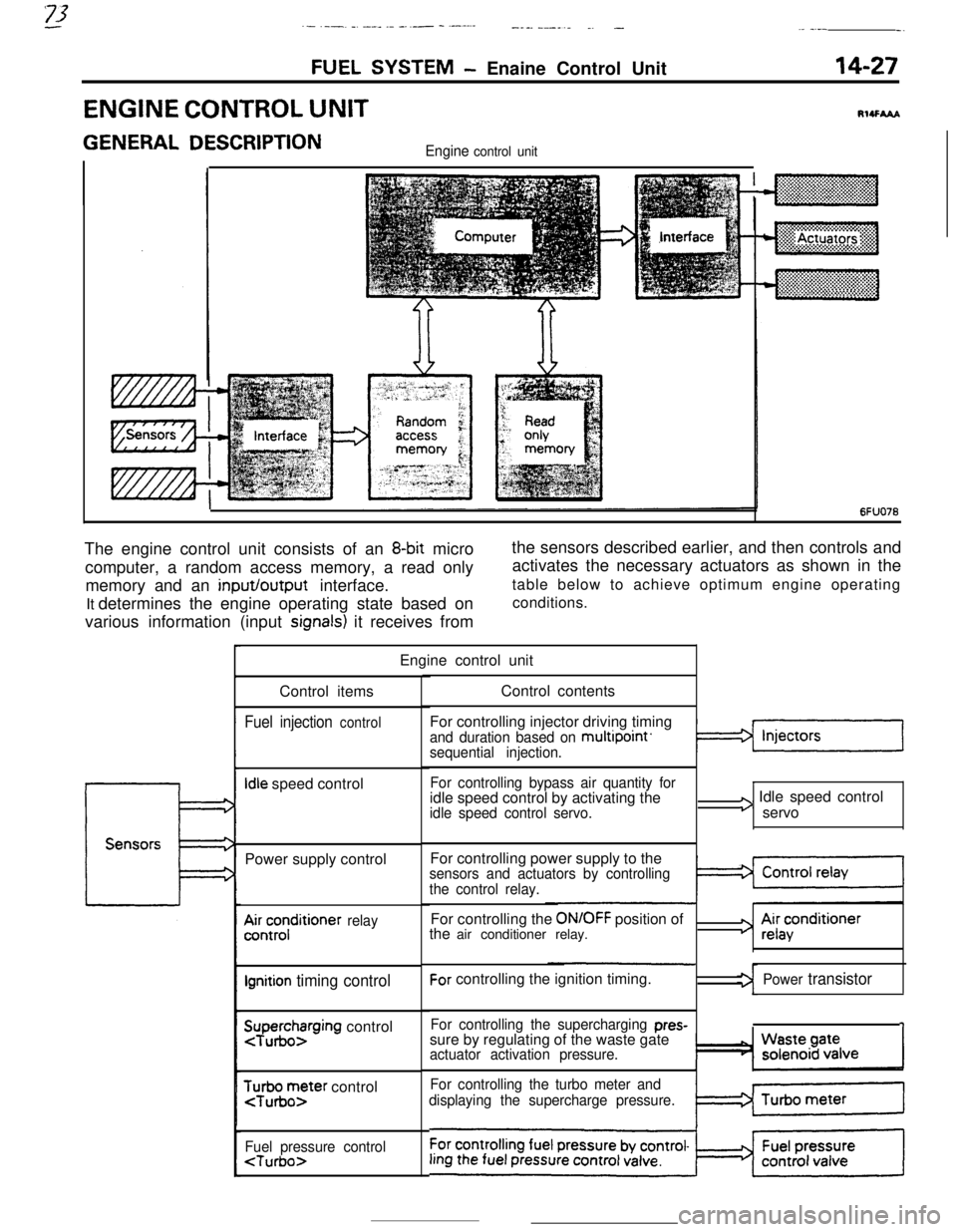
ENGINE CONTROL UNITRI4FhAA
GENERAL DESCRIPTIONEngine control unit
~
~~:~~~~~~~~~:~~
~. . . . .. .. . . . ... . . . . ... .. :+:.:.:.:.:.:.:.~.:.~+~.
6FUO76The engine control unit consists of an
8-bit micro
computer, a random access memory, a read only
memory and an input/output interface.
It determines the engine operating state based on
various information (input
signals) it receives fromthe sensors described earlier, and then controls and
activates the necessary actuators as shown in the
table below to achieve optimum engine operating
conditions.
Engine control unit
Control items
Fuel injection control
Idle speed control
Power supply control
A&;;;ditioner relay
Ignition timing control
SuTpuegohzrging control
$r;ir;;ter control
Fuel pressure control
For controlling injector driving timing
and duration based on multipoint’sequential injection.
For controlling bypass air quantity foridle speed control by activating the
idle speed control servo.
I3 Idle speed control
servo
For controlling power supply to the
sensors and actuators by controlling
the control relay.For controlling the
ON/OFF position of
the air conditioner relay.For controlling the ignition timing.
For controlling the supercharging pres-sure by regulating of the waste gate
actuator activation pressure.
For controlling the turbo meter and
displaying the supercharge pressure.
3 Ai;acenditioner
Power transistor
1
Page 141 of 391
FUEL SYSTEM- Engine Control Unit14-29
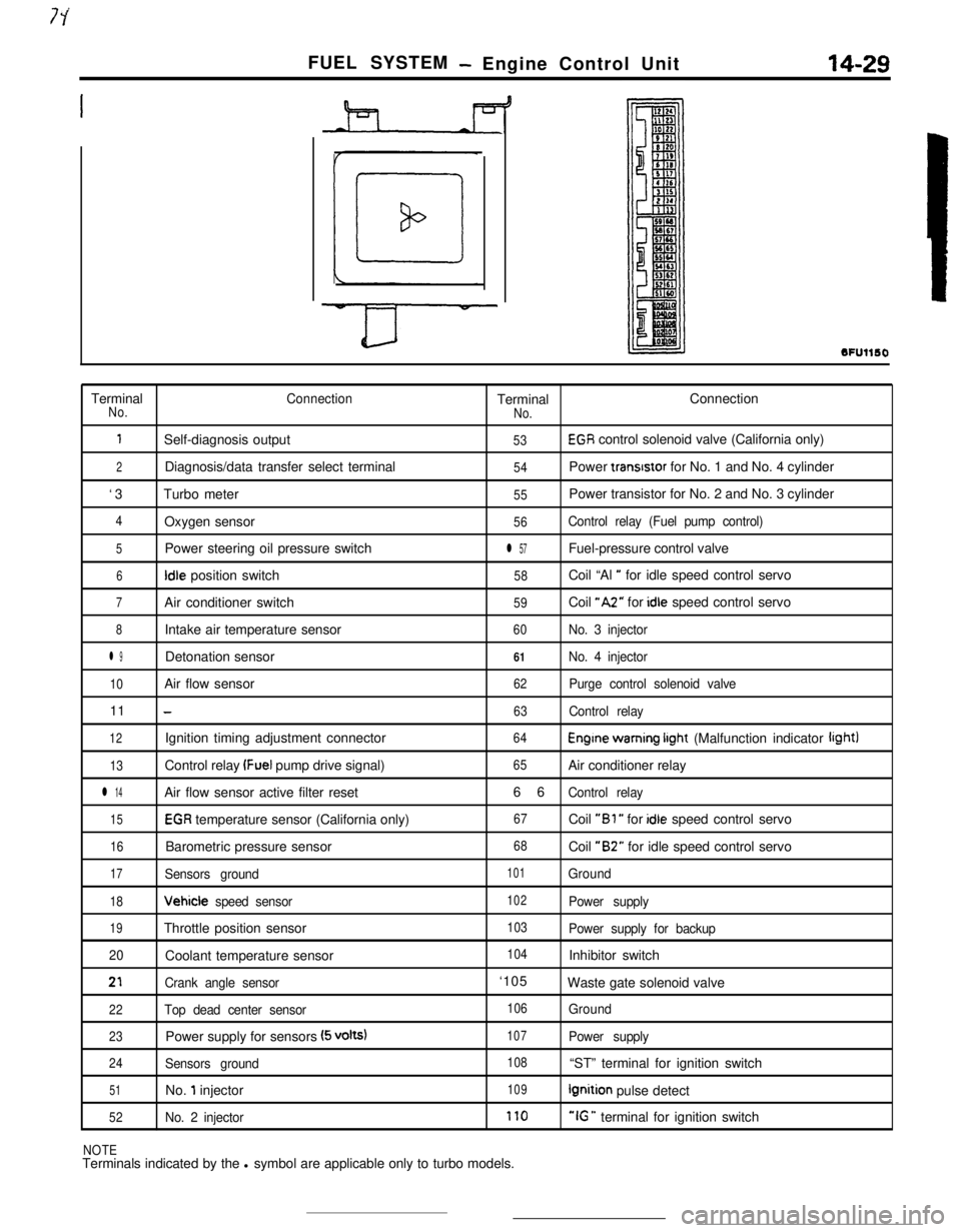
SFUllSOTerminal
ConnectionTerminalConnectionNo.
No.
1Self-diagnosis output53EGR control solenoid valve (California only)
2Diagnosis/data transfer select terminal54Power transrstor for No. 1 and No. 4 cylinder
‘3Turbo meter
55Power transistor for No. 2 and No. 3 cylinder
4Oxygen sensor56Control relay (Fuel pump control)
5Power steering oil pressure switchl 57Fuel-pressure control valve
6Idle position switch58Coil “Al ” for idle speed control servo
7Air conditioner switch59Coil “A2” for idle speed control servo
8Intake air temperature sensor60No. 3 injector
l 9Detonation sensor61No. 4 injector
10Air flow sensor62Purge control solenoid valve11
-63Control relay
12Ignition timing adjustment connector64Engine warning irght (Malfunction indicator light)
13Control relay (Fuel pump drive signal)65Air conditioner relay
l 14Air flow sensor active filter reset66Control relay
15EGR temperature sensor (California only)67Coil “Bl ” for idle speed control servo
16Barometric pressure sensor68Coil “B2” for idle speed control servo
17Sensors ground101Ground
18Vehicle speed sensor102Power supply
19Throttle position sensor103Power supply for backup
20Coolant temperature sensor
104Inhibitor switch
21Crank angle sensor‘105
Waste gate solenoid valve
22Top dead center sensor106Ground
23Power supply for sensors (5 volts)107Power supply
24Sensors ground108“ST” terminal for ignition switch
51No. 1 injector109Ignition pulse detect
52No. 2 injector170“IG ” terminal for ignition switch
NOTETerminals indicated by the l symbol are applicable only to turbo models.
Page 142 of 391
14-30SELF-DIAGNOSISFUEL SYSTEM- Engine Control Unit
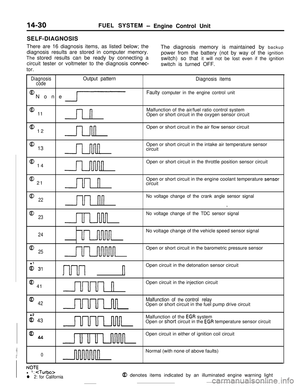
There are 16 diagnosis items, as listed below; the
diagnosis results are stored in computer memory.The diagnosis memory is maintained by backup
The stored results can be ready by connecting apower from the battery (not by way of the ignition
circuit tester or voltmeter to the diagnosis
connec-switch) so that it will not be lost even if the ignition
switch is turned OFF.
tor.
DiagnosisOutput pattern
codeEl
None
lP
@ 11l-l
@ 12n@ 13
@ 14
@ 21Ul n
Diagnosis items
Faulty computer in the engine control unitMalfunction of the air/fuel ratio control system
Open or short circuit in the oxygen sensor circuit
Open or short circuit in the air flow sensor circuit
Open or short circuit in the intake air temperature sensor
circuit
Open or short circuit in the throttle position sensor circuit
Open or short circuit in the engine coolant temperature sensor
circuit
022u1 nn
No voltage change of the crank angle sensor signal
,
@
23
u u-inn
No voltage change of the TDC sensor signal
24uu-uvinnnnNo voltage change of the vehicle speed sensor signal
Q25uuuuuunnnnnOpen or short circuit in the barometric pressure sensor
2 31I-~-~---~ nOpen circuit in the detonation sensor circuit
@ 41uuul nOpen circuit in the injection circuit
042UUuLJul
Malfunction of the control relayOpen or short circuit in the fuel pump drive circuit
z 43UUULnlulMalfunction of the
EGR system
Open or short circuit in the EGR temperature sensor circuit
%4u u u uvinnOpen circuit in either of ignition coil circuit
0nNormal (with none of above faults)
. IA-r-NUltl 1:
Page 143 of 391
FUEL SYSTEM - Engine Control Unit14-31
r
L
IMPI
Ground
1 Engine control unit
Engine wam-
$b?Stionindicator
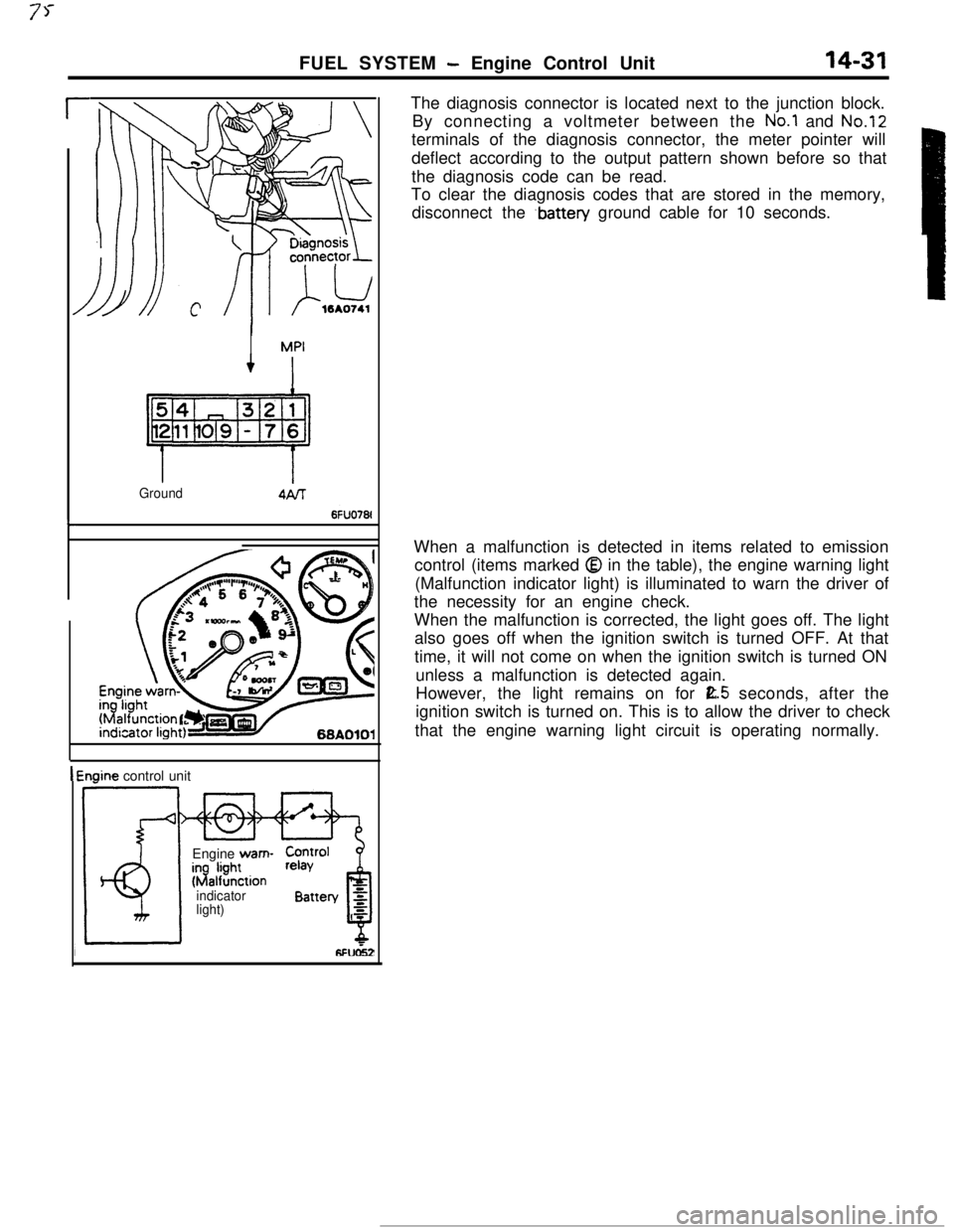
light)The diagnosis connector is located next to the junction block.
By connecting a voltmeter between the
No.1 and No.12terminals of the diagnosis connector, the meter pointer will
deflect according to the output pattern shown before so that
the diagnosis code can be read.
To clear the diagnosis codes that are stored in the memory,
disconnect the
.battery ground cable for 10 seconds.
When a malfunction is detected in items related to emission
control (items marked
Q in the table), the engine warning light
(Malfunction indicator light) is illuminated to warn the driver of
the necessity for an engine check.
When the malfunction is corrected, the light goes off. The light
also goes off when the ignition switch is turned OFF. At that
time, it will not come on when the ignition switch is turned ON
unless a malfunction is detected again.
However, the light remains on for
E.5 seconds, after the
ignition switch is turned on. This is to allow the driver to check
that the engine warning light circuit is operating normally.