ignition MITSUBISHI ECLIPSE 1990 Service Manual
[x] Cancel search | Manufacturer: MITSUBISHI, Model Year: 1990, Model line: ECLIPSE, Model: MITSUBISHI ECLIPSE 1990Pages: 391, PDF Size: 15.27 MB
Page 9 of 391
GENERAL - Technical Featureso-5ENGINE
The engines are the transverse-mounted engine
especially for front-engine/front-wheeldrive orfront-engine/4-wheel drive models, the
2.OL DOHC
16-valve engine with high-performance, silent-
operation,low-vibration,low-noise,low-fuel-
consumption features, an engine that fully displays
the most
up-todate engine technology.
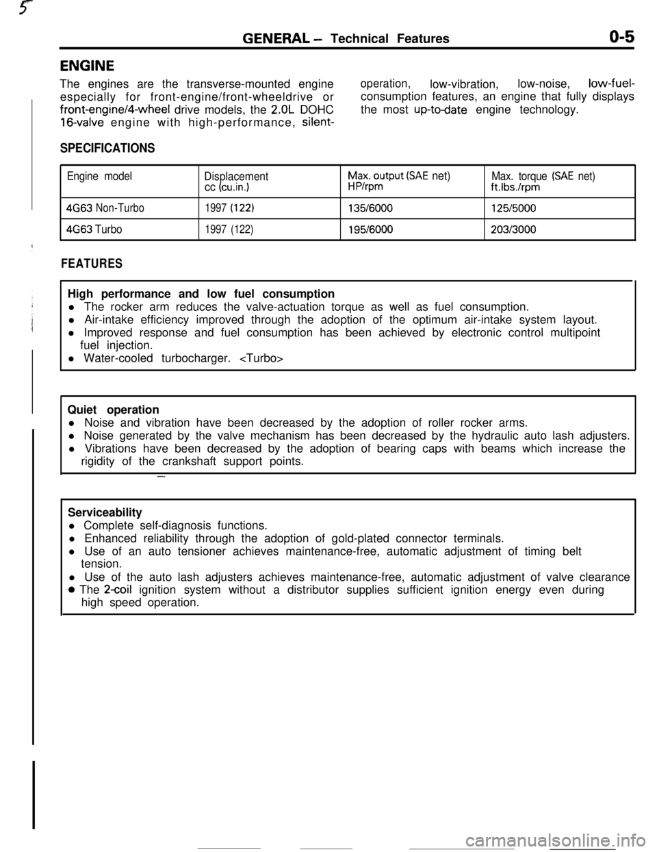
SPECIFICATIONS
Engine model
Displacement
cc (cu.in.1
h$xo$put (SAE net)Max. torque (SAE net)
ft.Ibs./rpm
4G63Non-Turbo1997(122)135/6000125/5000
4663Turbo1997(122)195/6000203/3000
FEATURESHigh performance and low fuel consumption
l The rocker arm reduces the valve-actuation torque as well as fuel consumption.
l Air-intake efficiency improved through the adoption of the optimum air-intake system layout.
l Improved response and fuel consumption has been achieved by electronic control multipoint
fuel injection.
l Water-cooled turbocharger.
Quiet operation
l Noise and vibration have been decreased by the adoption of roller rocker arms.
l Noise generated by the valve mechanism has been decreased by the hydraulic auto lash adjusters.
l Vibrations have been decreased by the adoption of bearing caps with beams which increase the
rigidity of the crankshaft support points.
-Serviceability
l Complete self-diagnosis functions.
l Enhanced reliability through the adoption of gold-plated connector terminals.
l Use of an auto tensioner achieves maintenance-free, automatic adjustment of timing belt
tension.
l Use of the auto lash adjusters achieves maintenance-free, automatic adjustment of valve clearance
.o The 2coil ignition system without a distributor supplies sufficient ignition energy even during
high speed operation.
Page 10 of 391
O-6GENERAL - Technical Features
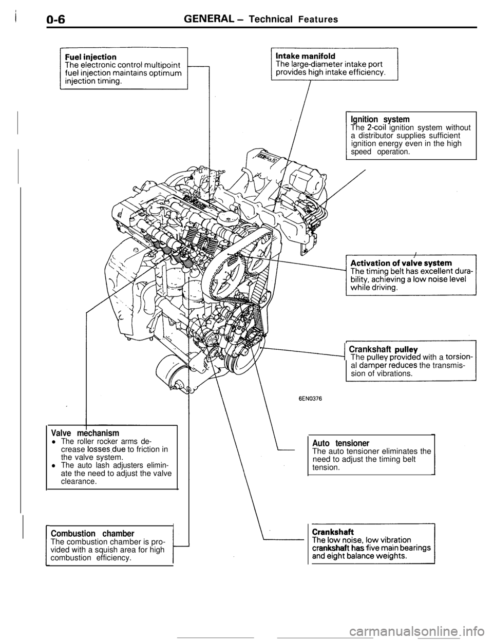
Valve mechanisml The roller rocker arms de-crease losses.due to friction in
the valve system.
l The auto lash adjusters elimin-ate the need to adjust the valve
clearance.
ICombustion chamberThe combustion chamber is pro-
vided with a squish area for high
combustion efficiency.
tJ
Ignition systemThe 2coil ignition system without
a distributor supplies sufficient
ignition energy even in the high
speed operation.
76-4 Crankshaft pu!leyThe oullev orovrded with a torsion-
al
da’mper ieduces the transmis-
sion of vibrations.
EN0376
Auto tensionerThe auto tensioner eliminates the
need to adjust the timing belt
tension.
]Icrankshaft has five marn bearings
Page 11 of 391
GENERAL -Technical Featureso-74WD
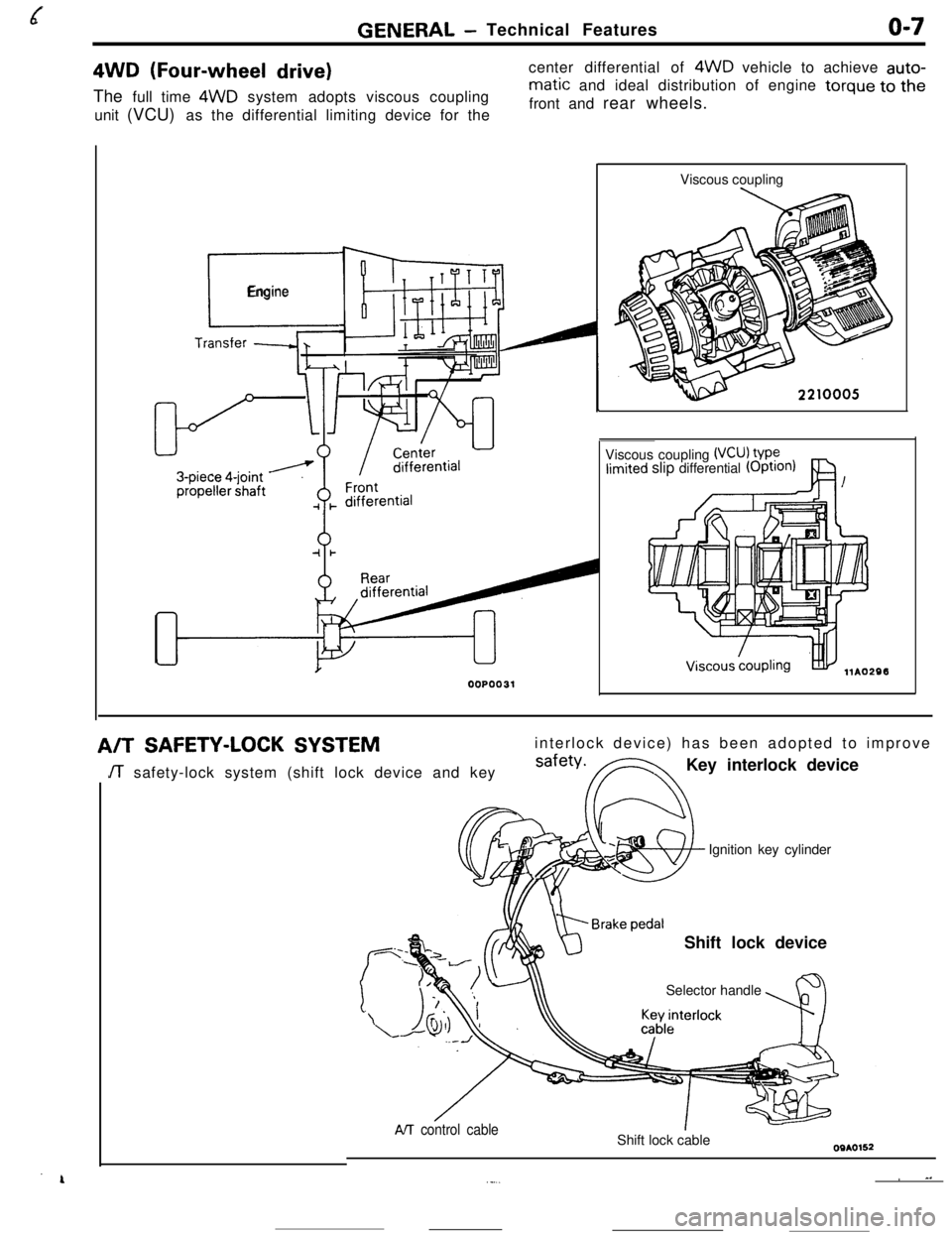
(Four-wheel drive)The full time 4WD system adopts viscous coupling
unit (VCU) as the differential limiting device for thecenter differential of 4WD vehicle to achieve auto-
matic and ideal distribution of engine torque to the
front and rear wheels.
r_
Engine
00P0031Viscous coupling
Viscous coupling
(VCU) VP?limited slip differential (OptIOn)
A/TSAFETY-LOCK SYSTEMinterlock device) has been adopted to improve
JT safety-lock system (shift lock device and keysafety*FNKey interlock device
Ignition key cylinder
Shift lock device
Selector handle
AIT control cableShift lock cable
~ ^.._...
Page 55 of 391
ELECTRICAL - Fuses8-3q
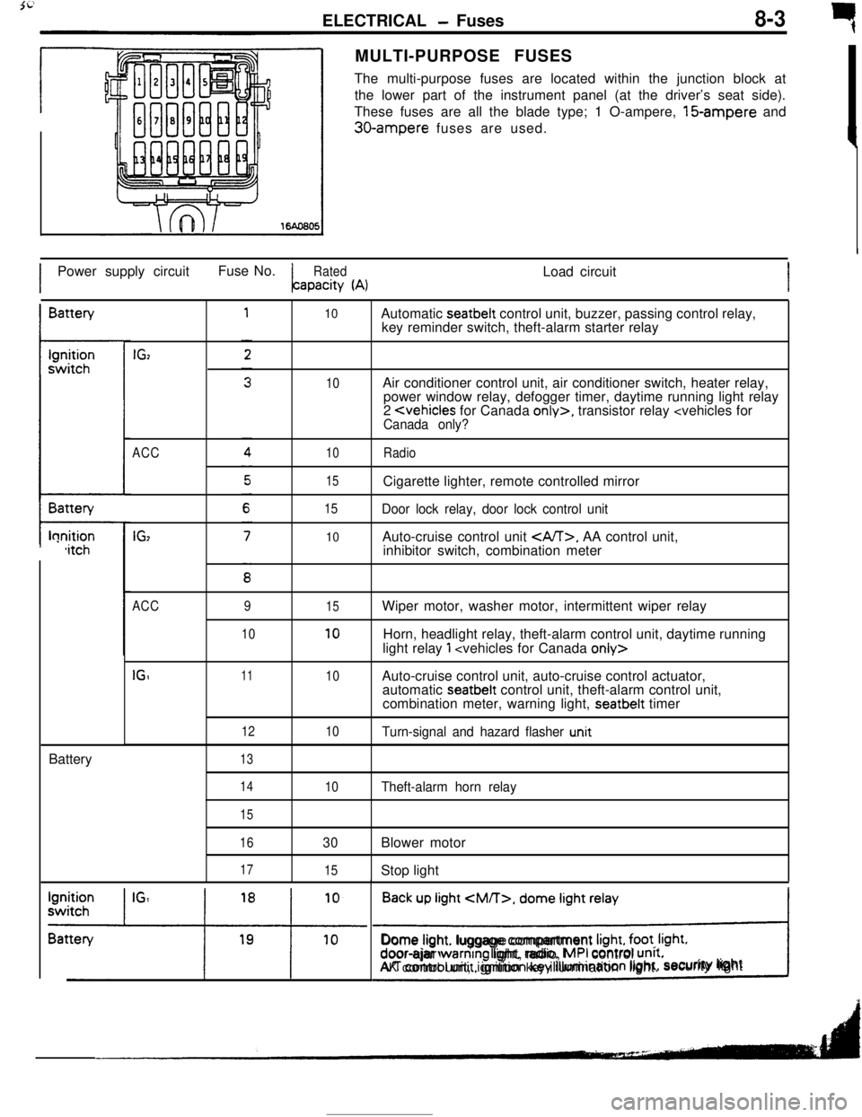
rMULTI-PURPOSE FUSES
The multi-purpose fuses are located within the junction block at
the lower part of the instrument panel (at the driver’s seat side).
These fuses are all the blade type; 1 O-ampere, 15-ampere and
30-ampere fuses are used.
IPower supply circuitFuse No.
RatedLoad circuitapacity
(A)IBattery
t-lonition,itchBattery
IGz
ACC
IG,
10
10
10
15
15
10Automatic seatbelt control unit, buzzer, passing control relay,
key reminder switch, theft-alarm starter relay
Air conditioner control unit, air conditioner switch, heater relay,
power window relay, defogger timer, daytime running light relay
2
Door lock relay, door lock control unitAuto-cruise control unit
, AA control unit,
inhibitor switch, combination meter
ACC
IGI9
1011
12
1315
10
10
10Wiper motor, washer motor, intermittent wiper relay
Horn, headlight relay, theft-alarm control unit, daytime running
light relay
1
automatic seatbelt control unit, theft-alarm control unit,
combination meter, warning light, seatbelt timer
Turn-signal and hazard flasher u.nit
14
15
16
17
10Theft-alarm horn relay
30Blower motor
15Stop light
Back up light
CM/T>, dome light relay
!Dome light. luggage compartment
Irght, foot. Irght.door-ajar warntng light, radio, MPI control unrt.AK control unit, ignition key illumination light.security lightI
Page 67 of 391
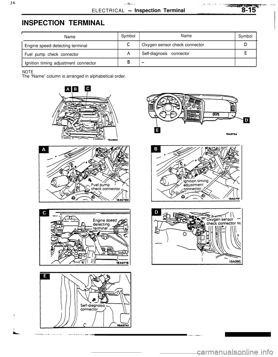
. . .&L : __,ELECTRICAL
- Inspection Terminal
INSPECTION TERMINAL
INameSymbolNameEngine speed detecting terminal
COxygen sensor check connector
Fuel pump check connectorASelf-diagnosis connectorIgnition timing adjustment connector
B -
NOTEThe “Name” column is arranged in alphabetical order.
Symbol
D
E16Ao734
Page 74 of 391
8-22ELECTRICAL - Lighting--Ignition ON
switch OFF
prDoor ON
switch OFF
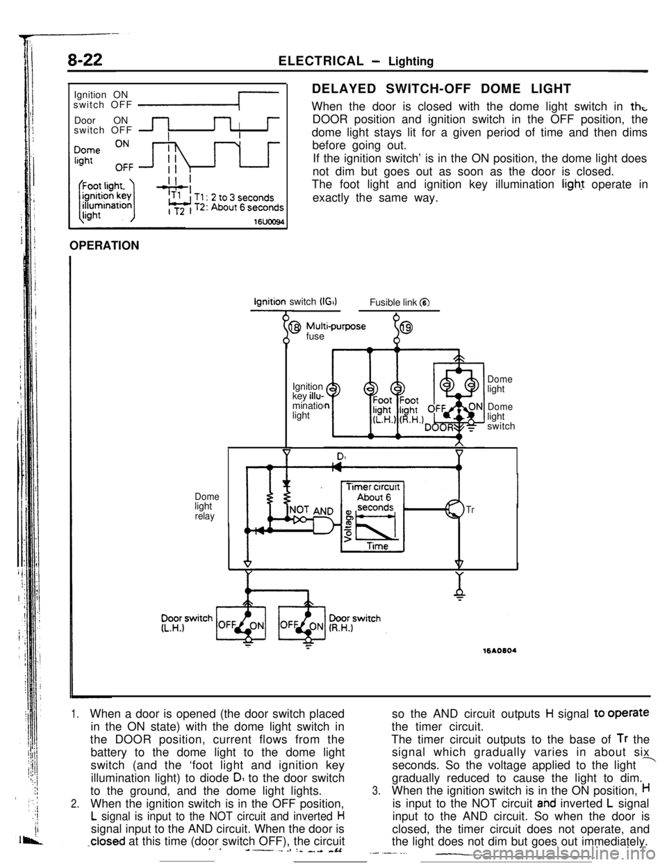
IDELAYED SWITCH-OFF DOME LIGHT
When the door is closed with the dome light switch in
thtDOOR position and ignition switch in the OFF position, the
dome light stays lit for a given period of time and then dims
before going out.
If the ignition switch’ is in the ON position, the dome light does
not dim but goes out as soon as the door is closed.
The foot light and ignition key illumination light operate in
exactly the same way.
16UOO94OPERATIONIgnition switch
(G)Fusible link a
Domelight
relay
9 Mutti-purpose
fuse
%69Ignition
key illu-
minatio
light
Domelight
Domelight
switch
Tr
;:16AO604
1.When a door is opened (the door switch placed
in the ON state) with the dome light switch in
the DOOR position, current flows from the
battery to the dome light to the dome light
switch (and the ‘foot light and ignition key
illumination light) to diode
DI to the door switch
to the ground, and the dome light lights.
2.When the ignition switch is in the OFF position,
L signal is input to the NOT circuit and inverted Hsignal input to the AND circuit. When the door is
-closed at this time (door switch OFF), the circuit
. .----es :- _.a -&Aso the AND circuit outputs
H signal to operate
the timer circuit.
The timer circuit outputs to the base of
Tr the
signal which gradually varies in about six
seconds. So the voltage applied to the light
-gradually reduced to cause the light to dim.
3.When the ignition switch is in the ON position,His input to the NOT circuit
ahd inverted L signal
input to the AND circuit. So when the door is
closed, the timer circuit does not operate, and
the light does not dim but goes out immediately.
_- .-._. ._-__._
Page 77 of 391
IGNITION SYSTEMELECTRICAL - Engine Electrical8-25
I
Sensors
Engine control unitlgnltlon switch
Battery
11 IPower transfstor
hhP 1
Ilgnltion coil
C To tachometerTerminal for engine
speed detectton
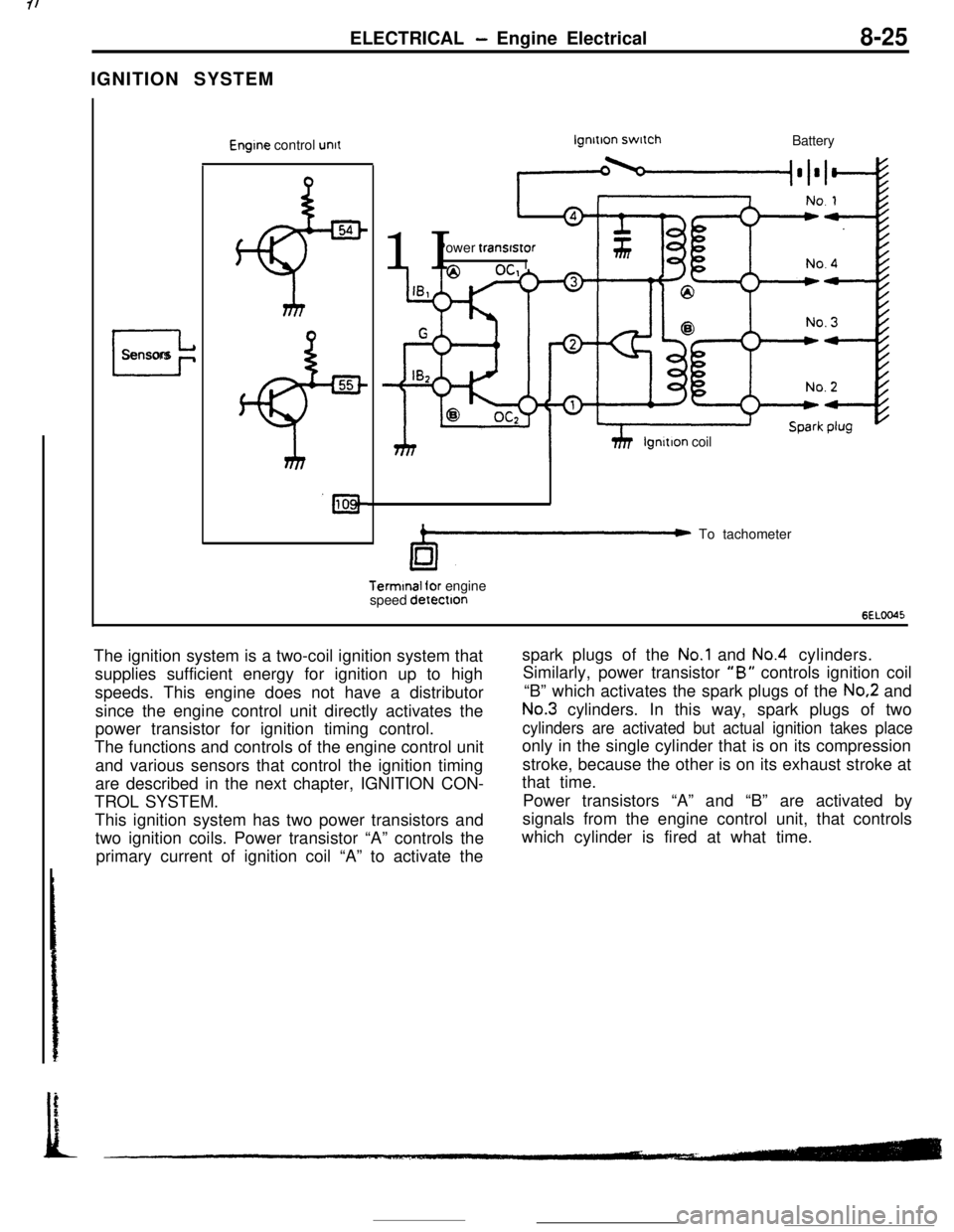
6ELOO45The ignition system is a two-coil ignition system that
supplies sufficient energy for ignition up to high
speeds. This engine does not have a distributor
since the engine control unit directly activates the
power transistor for ignition timing control.
The functions and controls of the engine control unit
and various sensors that control the ignition timing
are described in the next chapter, IGNITION CON-
TROL SYSTEM.
This ignition system has two power transistors and
two ignition coils. Power transistor “A” controls the
primary current of ignition coil “A” to activate thespark plugs of the
No.1 and No.4 cylinders.
Similarly, power transistor
“B” controls ignition coil
“B” which activates the spark plugs of the
No.2 and
No.3 cylinders. In this way, spark plugs of two
cylinders are activated but actual ignition takes placeonly in the single cylinder that is on its compression
stroke, because the other is on its exhaust stroke at
that time.
Power transistors “A” and “B” are activated by
signals from the engine control unit, that controls
which cylinder is fired at what time.
Page 78 of 391
8-26ELECTRICAL - Engine Electrical
No.:
4Signal unit for
, tachometer
71
x
No. 3
6EL0025
Capa &orCylinderNo. mark
6EL0057
To No. 1spark plug
To No. 4
spark plug
To No. 3spark plug
To No. 2spark plug
6EL005t
OC,IB, G
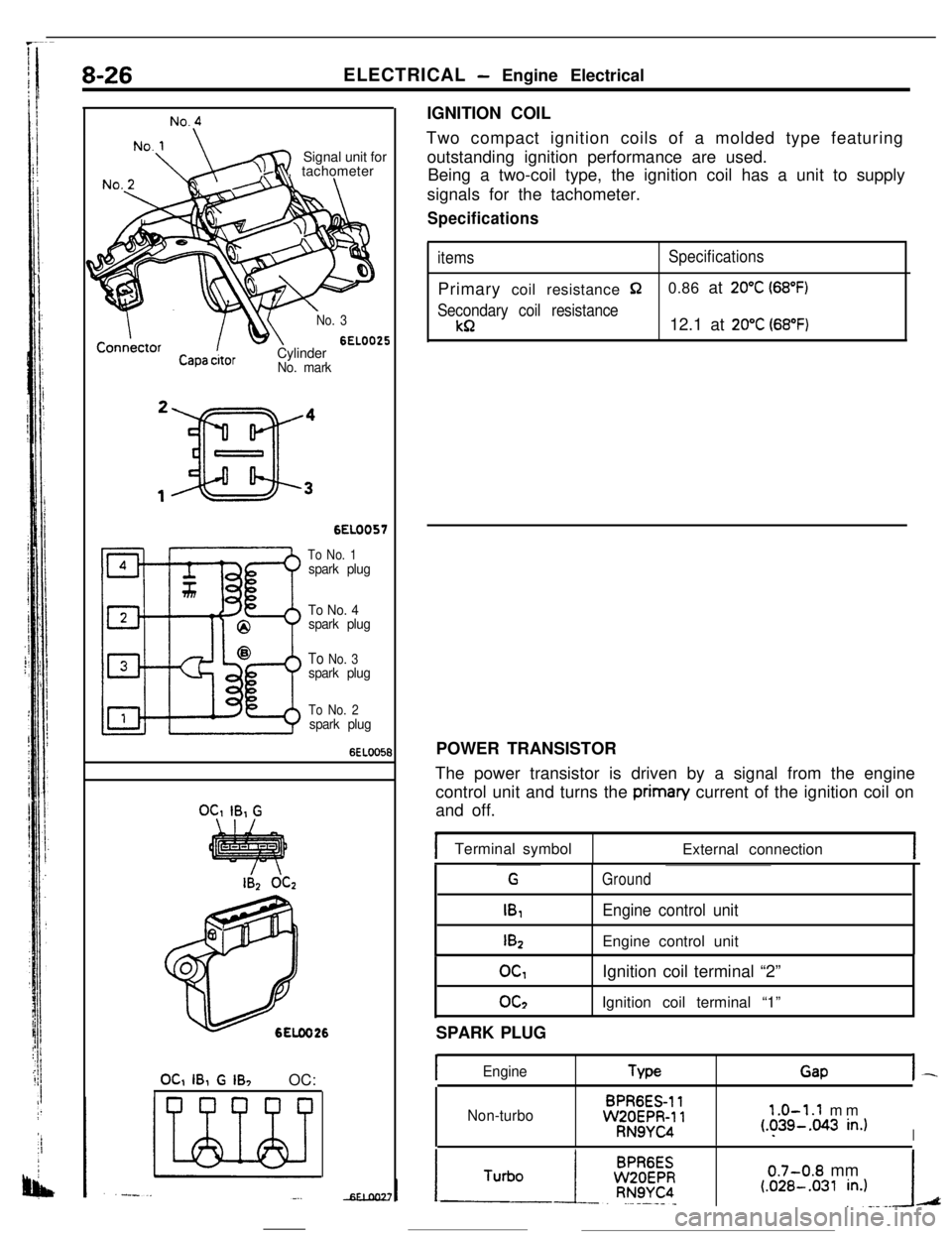
OC, IB, G IB, OC:IGNITION COIL
Two compact ignition coils of a molded type featuring
outstanding ignition performance are used.
Being a two-coil type, the ignition coil has a unit to supply
signals for the tachometer.
Specifications
itemsSpecificationsPrimary coil resistance
$20.86 at 20°C (68°F)
Secondary coil resistance
kR12.1 at 20°C (68°F)POWER TRANSISTOR
The power transistor is driven by a signal from the engine
control unit and turns the priman/ current of the ignition coil on
and off.
Terminal symbol
External connection
G
IB,
I&
Ground
Engine control unitEngine control unit
OGoc2Ignition coil terminal “2”
Ignition coil terminal “1”
SPARK PLUG
IEngineTypeGapI-
Non-turboBPR6ES-11WZOEPR-11RN9YC4
1.0-1.1 mm(.?39-.043 in.)I
0.7-0.8 mm(.OZB-.031 in.)A
Page 79 of 391
-----. _-- ___ELECTRICAL
- Engine Electrical8-27IGNITION TIMING CONTROL SYSTEM
Air flow sensor
Engtne control unit
Intake air temp. sensor
Barometric pressure sensor
Engine coolant temp. sensorIdle position switch
:+
Top dead center sensor
Crank angle sensorVehicle speed sensor
;+Ignition switch “ST” terminal
Detonation sensor for
turbo engine only
4 Power= tranststor “B”P Ignition coil
109
_
I
1
12a”- To tachometer
Terminal for engine speed detection
Terminal for ignition,timing
and idle speed adjustment
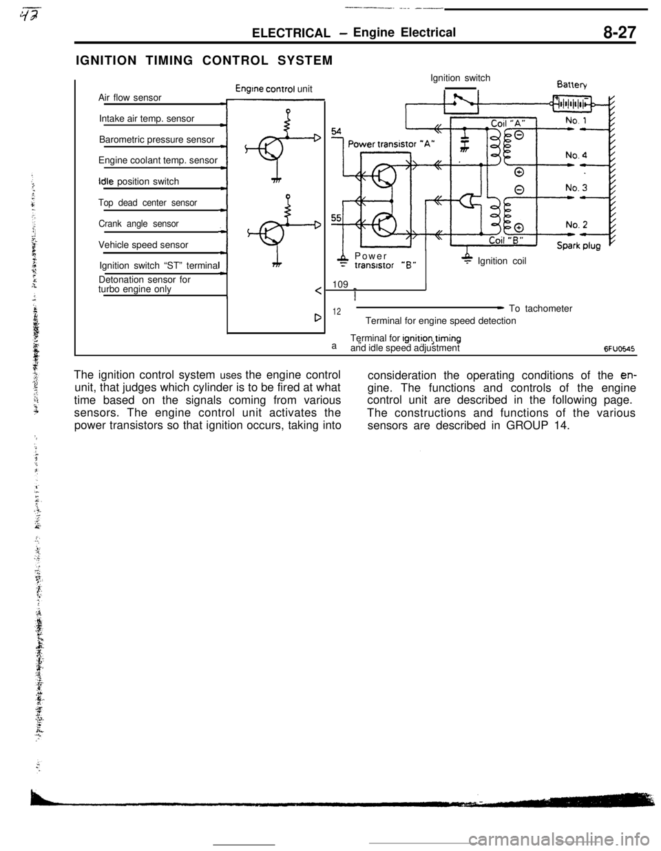
6FUoE.45The ignition control system uses the engine control
consideration the operating conditions of the
en-unit, that judges which cylinder is to be fired at what
gine. The functions and controls of the engine
time based on the signals coming from variouscontrol unit are described in the following page.
sensors. The engine control unit activates the
The constructions and functions of the various
power transistors so that ignition occurs, taking into
sensors are described in GROUP 14.
Page 80 of 391
8-28ELECTRICAL- Engine Electrical
IGNITION TIMING CONTROL
Reading of Input signallgnitlon power
distribution control
(selection of power
transistor actlvatlon)Control mode
I II II IControl mode
dectsion data
Basic energlzatlon
I’
Engine control unitPower
Powertranststor “A”tranststor “B”
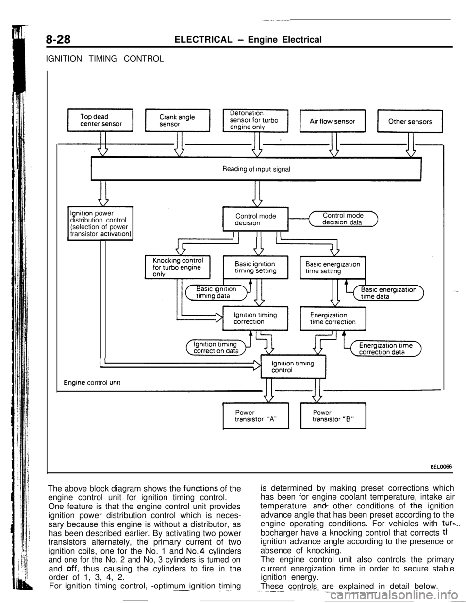
6ELOO66The above block diagram shows the
fljnctions of the
engine control unit for ignition timing control.
One feature is that the engine control unit provides
ignition power distribution control which is neces-
sary because this engine is without a distributor, as
has been described earlier. By activating two power
transistors alternately, the primary current of two
ignition coils, one for the No. 1 and No.4 cylinders
and one for the No. 2 and No, 3 cylinders is turned onand
off. thus causing the cylinders to fire in the
order of 1, 3, 4, 2.
For ignition timing control, -optimum ignition timing.^--_
_. -.is determined by making preset corrections which
has been for engine coolant temperature, intake air
temperature an& other conditions of the ignition
advance angle that has been preset according to the
engine operating conditions. For vehicles with
tur=_.bocharger have a knocking control that corrects tl
ignition advance angle according to the presence or
absence of knocking.
The engine control unit also controls the primary
current energization time in order to secure stable
ignition energy.
These controls are explained in detail below.
--. .----- ---- --- ___. .-. ___.,.__