fuel MITSUBISHI ECLIPSE 1990 Owner's Guide
[x] Cancel search | Manufacturer: MITSUBISHI, Model Year: 1990, Model line: ECLIPSE, Model: MITSUBISHI ECLIPSE 1990Pages: 391, PDF Size: 15.27 MB
Page 132 of 391
FUEL SYSTEM - Sensors
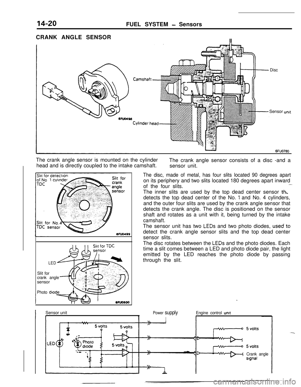
CRANK ANGLE SENSOR
II
DiscSensor
The crank angle sensor is mounted on the cylinder
head and is directly coupled to the intake camshaft.The crank angle sensor consists of a disc -and a
sensor unit.
Mu0499Slit for
crank anglesensor
Photo diode
LED
The disc, made of metal, has four slits located 90 degrees aparton its periphery and two slits located 180 degrees apart inward
of the four slits.
-The inner slits are used by the top dead center sensor
th,detects the top dead center of the No.
1 and No. 4 cylinders,
and the outer four slits are used by the crank angle sensor that
detects the crank angle. The disc is positioned on the sensor
shaft and rotates as a unit with it, being turned by the intake
camshaft.The sensor unit has two
LEDs and two photo diodes, used’to
detect the crank angle sensor slits and the top dead center
sensor slits.
The disc rotates between the
LEDs and the photo diodes. Each
time a slit comes between a LED and photo diode pair, the light
emitted by the LED reaches the photo diode by passing
through the slit.
Sensor unit
I I1
Power supply
I
Engine control untt
r
Crank angleslgnal
Page 133 of 391
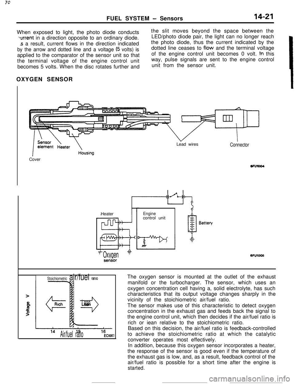
FUEL SYSTEM - Sensors14-21When exposed to light, the photo diode conducts
urrent in a direction opposite to an ordinary diode.
.s a result, current flows in the direction indicated
by the arrow and dotted line and a voltage (5 volts) isapplied to the comparator of the sensor unit so that
the terminal voltage of the engine control unit
becomes 5 volts. When the disc rotates further andthe slit moves beyond the space between the
LED/photo diode pair, the light can no longer reach
the photo diode, thus the current indicated by the
dotted line ceases to flow and the terminal voltage
of the engine control unit becomes 0 volt.
tn this
way, pulse signals are sent to the engine control
unit from the sensor unit.
OXYGEN SENSOR
k
1 ~~~~t13ate~ousingCoverLead wiresConnectorHeater
Enginecontrol unit6FUlOO5
- Oxygen‘-serisor
The oxygen sensor is mounted at the outlet of the exhaust
manifold or the turbocharger. The sensor, which uses an
oxygen concentration cell having a, solid electrolyte, has such
characteristics that its output voltage changes sharply in the
vicinity of the stoichiometric air/fuel ratio.
The sensor makes use of this characteristic to detect oxygen
concentration in the exhaust gas and feeds back the signal to
the engine control unit, which then decides if the air/fuel ratio is
rich or iean relative to the stoichiometric ratio.
Based on this decision, the air/fuel ratio is feedback-controlled
to achieve the stoichiometric ratio at which the catalytic
converter operates most effectively.
In addition, because this oxygen sensor incorporates a heater,
the response of the sensor is good even if the temperature of
the exhaust gas is low, and, as a result, feedback control of the
air/fuel ratio is possible for a short time after the engine is
started.
Stoichiometric air/fuel ratlo
r3
Lean
Air/fuel ratioEC1007
Page 134 of 391
14-22FUEL SYSTEM - Sensors
VEHICLE SPEED SENSOR
L
Vehicle speessensor
Vehicle speed sensor
10*0051speed sensorEngine control unit
6FlJO604
1 revoluttonI
‘r’471
16245
7
B
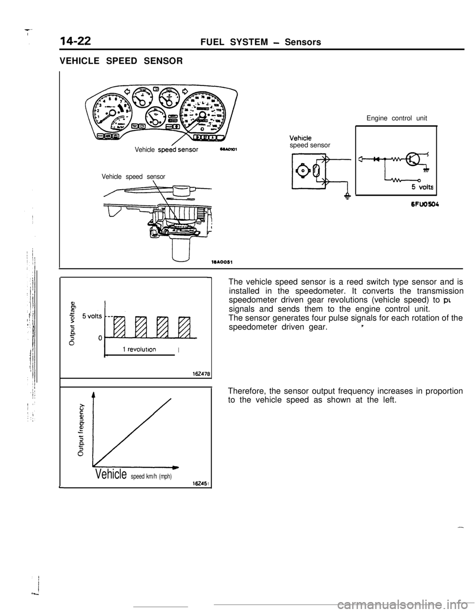
1Vehicle speed km/h (mph)The vehicle speed sensor is a reed switch type sensor and is
installed in the speedometer. It converts the transmission
speedometer driven gear revolutions (vehicle speed) to
ptsignals and sends them to the engine control unit.
The sensor generates four pulse signals for each rotation of the
speedometer driven gear.
5Therefore, the sensor output frequency increases in proportion
to the vehicle speed as shown at the left.
-
Page 135 of 391
‘7JFUEL SYSTEM
- Sensors14-23AIR CONDITIONER SWITCH
Batten/
-31 .,Air conditioner unitlSAO735‘Air conditioner
control unitI”.._. ,voltage
Dual pressureswitch
-f@ -//Q.j
/
Coolanttemperature6FU1148
switch
Engine control unit
3Air conditioner
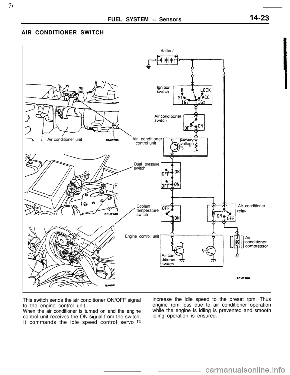
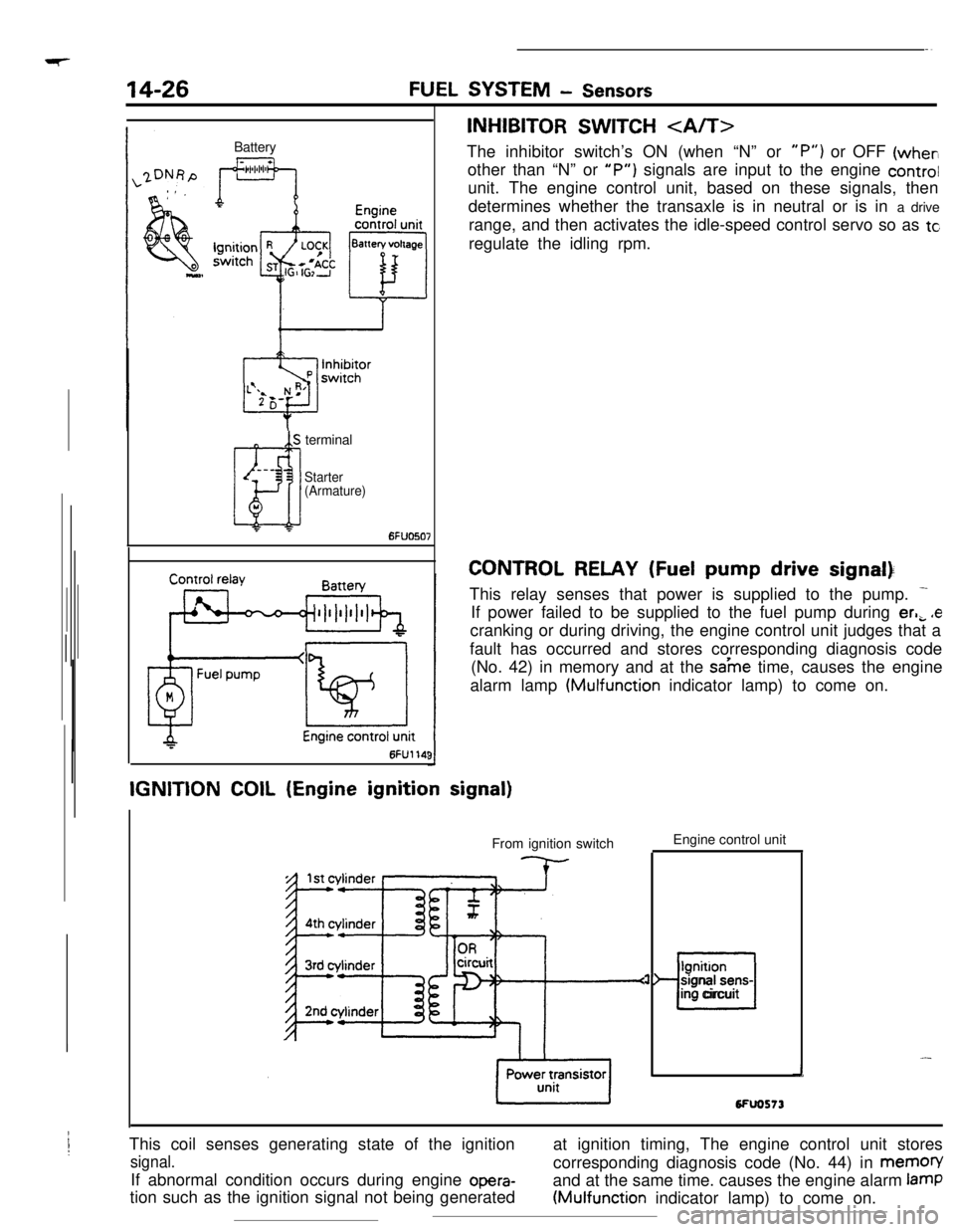
This switch sends the air conditioner ON/OFF signal
to the engine control unit.
When the air conditioner is turned on and the enginecontrol unit receives the ON
signal from the switch,
it commands the idle speed control servo
toincrease the idle speed to the preset rpm. Thus
engine rpm loss due to air conditioner operation
while the engine is idling is prevented and smooth
idling operation is ensured.
Page 136 of 391
--
,
14-24FUEL SYSTEM - Sensors
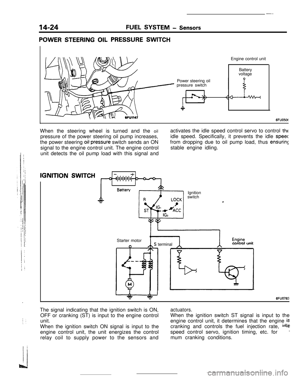
POWER STEERING OIL PRESSURE SWITCHEngine control unit
Power steering oil
pressure switchBattery
voltage
6FUO5OtIWhen the steering wheel is turned and the oil
pressure of the power steering oil pump increases,
the power steering oifpressure switch sends an ON
signal to the engine control unit. The engine control
unit detects the oil pump load with this signal andactivates the idle speed control servo to control
theidle speed. Specifically, it prevents the idle
speecfrom dropping due to oil pump load, thus
ensuringstable engine idling.IGNITION
SWITCH
1IBattery
Ignition
switch
Starter motor
aS terminalcontrol unit
6FUO762The signal indicating that the ignition switch is ON,
OFF or cranking (ST) is input to the engine control
unit.
When the ignition switch ON signal is input to the
engine control unit, the unit energizes the control
relay coil to supply power to the sensors and
actuators.When the ignition switch ST signal is input to the
engine control unit, it determines that the engine
iscranking and controls the fuel injection rate,
despeed control servo, ignition timing, etc. for
-mum cranking conditions.
Page 137 of 391

FUEL SYSTEM - Sensors14-25Terminal for
ignition timing
adjustment
l-l6FUO51:7
W$ht(/.
Piezo-electncelements
I6FUOSlO
DetonationEngine control
unit
sensor
I-
I t i A-- >--t.--‘-3 -
wt4rlIGNITION TlMlNG ADJUSTMENT TERMINAL
This terminal
is used when adjusting the basic ignition timing or
basic idle speed.
When this terminal is shorted to ground, the engine control unit
cancels the
ignition timing control and idle speed control, and
sets the ignition
timing and idle speed control servos in their
adjusting mode.
For the basic idle speed adjustment, the diagnosis terminal is
also shorted to ground.
DETONATION SENSOR
The detonation sensor is installed at a position where it can
detect, with a high degree of precision, knocking generated at
each cylinder; it detects cylinder block vibrations caused by
knocking, and outputs voltage proportional to the magnitude of
those vibrations.
Because cylinder block vibrations caused by knocking vary
from engine to engine, the engine control unit passes this
through a frequncy filter, detecting only the knocking, thus
resulting in a spark retardation of the ignition timing that
corresponds to the strength of the knocking.
Page 138 of 391
Page 139 of 391
‘73.- .-_ _ .-__ .- -..- - .-----___. _____^. -._ __--.
FUEL SYSTEM- Enaine Control Unit14-27
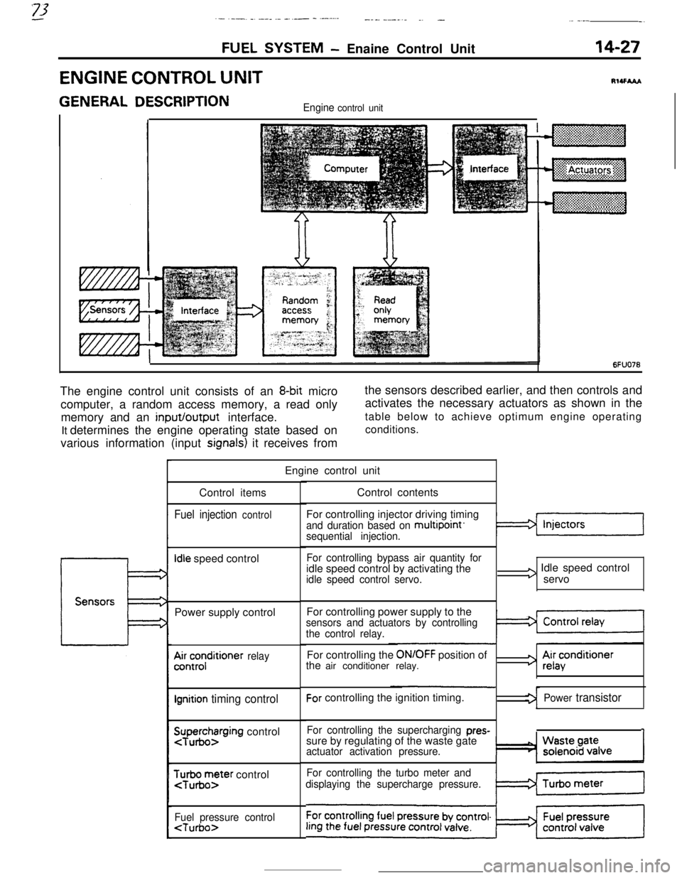
ENGINE CONTROL UNITRI4FhAA
GENERAL DESCRIPTIONEngine control unit
~
~~:~~~~~~~~~:~~
~. . . . .. .. . . . ... . . . . ... .. :+:.:.:.:.:.:.:.~.:.~+~.
6FUO76The engine control unit consists of an
8-bit micro
computer, a random access memory, a read only
memory and an input/output interface.
It determines the engine operating state based on
various information (input
signals) it receives fromthe sensors described earlier, and then controls and
activates the necessary actuators as shown in the
table below to achieve optimum engine operating
conditions.
Engine control unit
Control items
Fuel injection control
Idle speed control
Power supply control
A&;;;ditioner relay
Ignition timing control
SuTpuegohzrging control
$r;ir;;ter control
Fuel pressure control
For controlling injector driving timing
and duration based on multipoint’sequential injection.
For controlling bypass air quantity foridle speed control by activating the
idle speed control servo.
I3 Idle speed control
servo
For controlling power supply to the
sensors and actuators by controlling
the control relay.For controlling the
ON/OFF position of
the air conditioner relay.For controlling the ignition timing.
For controlling the supercharging pres-sure by regulating of the waste gate
actuator activation pressure.
For controlling the turbo meter and
displaying the supercharge pressure.
3 Ai;acenditioner
Power transistor
1
Page 140 of 391

---_-
14-28FUEL SYSTEM- Ennine Control Unit
The engine control unit has an
onboard diagnosis
function, which is used mainly to diagnose the
sensors, thus facilitating system checks and troub-leshooting. It also has a fail-safe/backup function tc
ensure passenger and vehicle safety.
Onboard self-
diagnosisMainly for detecting failure of sensors
and foroutputting diagnosis code.
for detecting failure of sensors, etc. related
toemission control and to turn ON warning light
(Malfunction indicator light).
> Codes can be read by voltmeter.
ENGINE CHECK light is turned
2 ON.
The engine control unit is mounted in the passenger compart-
ment, at the location indicated in the illustration.,
Page 141 of 391
FUEL SYSTEM- Engine Control Unit14-29
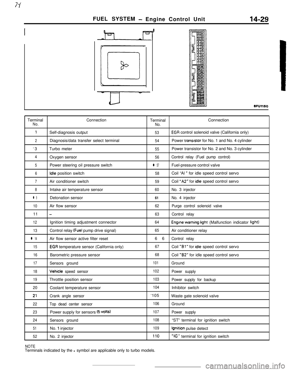
SFUllSOTerminal
ConnectionTerminalConnectionNo.
No.
1Self-diagnosis output53EGR control solenoid valve (California only)
2Diagnosis/data transfer select terminal54Power transrstor for No. 1 and No. 4 cylinder
‘3Turbo meter
55Power transistor for No. 2 and No. 3 cylinder
4Oxygen sensor56Control relay (Fuel pump control)
5Power steering oil pressure switchl 57Fuel-pressure control valve
6Idle position switch58Coil “Al ” for idle speed control servo
7Air conditioner switch59Coil “A2” for idle speed control servo
8Intake air temperature sensor60No. 3 injector
l 9Detonation sensor61No. 4 injector
10Air flow sensor62Purge control solenoid valve11
-63Control relay
12Ignition timing adjustment connector64Engine warning irght (Malfunction indicator light)
13Control relay (Fuel pump drive signal)65Air conditioner relay
l 14Air flow sensor active filter reset66Control relay
15EGR temperature sensor (California only)67Coil “Bl ” for idle speed control servo
16Barometric pressure sensor68Coil “B2” for idle speed control servo
17Sensors ground101Ground
18Vehicle speed sensor102Power supply
19Throttle position sensor103Power supply for backup
20Coolant temperature sensor
104Inhibitor switch
21Crank angle sensor‘105
Waste gate solenoid valve
22Top dead center sensor106Ground
23Power supply for sensors (5 volts)107Power supply
24Sensors ground108“ST” terminal for ignition switch
51No. 1 injector109Ignition pulse detect
52No. 2 injector170“IG ” terminal for ignition switch
NOTETerminals indicated by the l symbol are applicable only to turbo models.