display MITSUBISHI ECLIPSE 1990 Service Manual
[x] Cancel search | Manufacturer: MITSUBISHI, Model Year: 1990, Model line: ECLIPSE, Model: MITSUBISHI ECLIPSE 1990Pages: 391, PDF Size: 15.27 MB
Page 9 of 391
GENERAL - Technical Featureso-5ENGINE
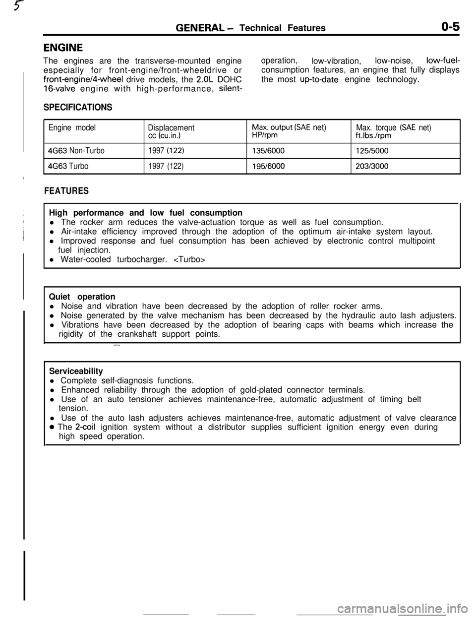
The engines are the transverse-mounted engine
especially for front-engine/front-wheeldrive orfront-engine/4-wheel drive models, the
2.OL DOHC
16-valve engine with high-performance, silent-
operation,low-vibration,low-noise,low-fuel-
consumption features, an engine that fully displays
the most
up-todate engine technology.
SPECIFICATIONS
Engine model
Displacement
cc (cu.in.1
h$xo$put (SAE net)Max. torque (SAE net)
ft.Ibs./rpm
4G63Non-Turbo1997(122)135/6000125/5000
4663Turbo1997(122)195/6000203/3000
FEATURESHigh performance and low fuel consumption
l The rocker arm reduces the valve-actuation torque as well as fuel consumption.
l Air-intake efficiency improved through the adoption of the optimum air-intake system layout.
l Improved response and fuel consumption has been achieved by electronic control multipoint
fuel injection.
l Water-cooled turbocharger.
Quiet operation
l Noise and vibration have been decreased by the adoption of roller rocker arms.
l Noise generated by the valve mechanism has been decreased by the hydraulic auto lash adjusters.
l Vibrations have been decreased by the adoption of bearing caps with beams which increase the
rigidity of the crankshaft support points.
-Serviceability
l Complete self-diagnosis functions.
l Enhanced reliability through the adoption of gold-plated connector terminals.
l Use of an auto tensioner achieves maintenance-free, automatic adjustment of timing belt
tension.
l Use of the auto lash adjusters achieves maintenance-free, automatic adjustment of valve clearance
.o The 2coil ignition system without a distributor supplies sufficient ignition energy even during
high speed operation.
Page 139 of 391
‘73.- .-_ _ .-__ .- -..- - .-----___. _____^. -._ __--.
FUEL SYSTEM- Enaine Control Unit14-27
ENGINE CONTROL UNITRI4FhAA
GENERAL DESCRIPTIONEngine control unit
~
~~:~~~~~~~~~:~~
~. . . . .. .. . . . ... . . . . ... .. :+:.:.:.:.:.:.:.~.:.~+~.
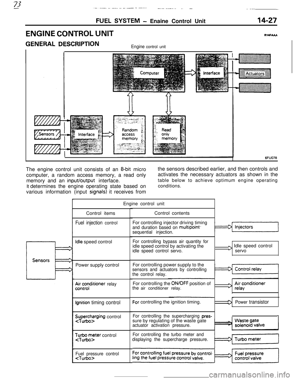
6FUO76The engine control unit consists of an
8-bit micro
computer, a random access memory, a read only
memory and an input/output interface.
It determines the engine operating state based on
various information (input
signals) it receives fromthe sensors described earlier, and then controls and
activates the necessary actuators as shown in the
table below to achieve optimum engine operating
conditions.
Engine control unit
Control items
Fuel injection control
Idle speed control
Power supply control
A&;;;ditioner relay
Ignition timing control
SuTpuegohzrging control
$r;ir;;ter control
Fuel pressure control
For controlling injector driving timing
and duration based on multipoint’sequential injection.
For controlling bypass air quantity foridle speed control by activating the
idle speed control servo.
I3 Idle speed control
servo
For controlling power supply to the
sensors and actuators by controlling
the control relay.For controlling the
ON/OFF position of
the air conditioner relay.For controlling the ignition timing.
For controlling the supercharging pres-sure by regulating of the waste gate
actuator activation pressure.
For controlling the turbo meter and
displaying the supercharge pressure.
3 Ai;acenditioner
Power transistor
1
Page 181 of 391
FUEL SYSTEM- Auto-cruise Control System14-69
ni2nnncisv,“y’I”“.-
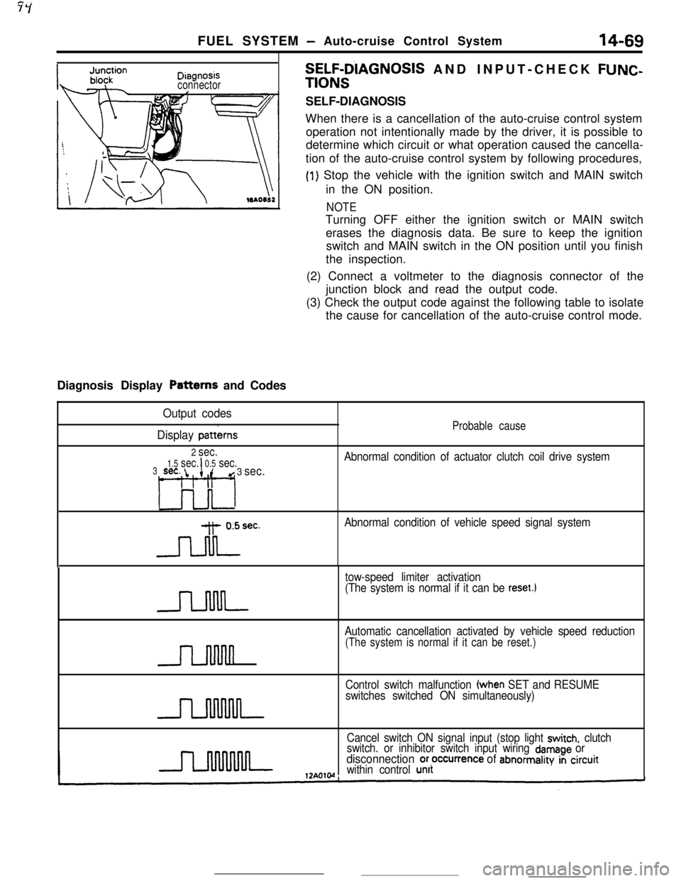
connectorDiagnosis Display Patterns and Codes
SELF-D’IAGNOSIS AND INPUT-CHECK FUNC-
TIONSSELF-DIAGNOSIS
When there is a cancellation of the auto-cruise control system
operation not intentionally made by the driver, it is possible to
determine which circuit or what operation caused the cancella-
tion of the auto-cruise control system by following procedures,
(1) Stop the vehicle with the ignition switch and MAIN switch
in the ON position.
NOTETurning OFF either the ignition switch or MAIN switch
erases the diagnosis data. Be sure to keep the ignition
switch and MAIN switch in the ON position until you finish
the inspection.
(2) Connect a voltmeter to the diagnosis connector of the
junction block and read the output code.
(3) Check the output code against the following table to isolate
the cause for cancellation of the auto-cruise control mode.
Output codes
Display
patterns
2 sec.
1.5 sec.I0.5 sec.3sec. id 3 sec.
L3o-l
-Jdrec.
Probable cause
Abnormal condition of actuator clutch coil drive system
Abnormal condition of vehicle speed signal system
tow-speed limiter activation
(The system is normal if it can be
reset.1
n
Automatic cancellation activated by vehicle speed reduction
(The system is normal if it can be reset.)
Control switch malfunction (when SET and RESUME
switches switched ON simultaneously)
Cancel switch ON signal input (stop light
switch, clutch
switch. or inhibitor switch input wiring damage ordisconnection or,occurrence of abnormality in circuitwithin control unit
Page 182 of 391
14-70
-_FUEL SYSTEM
- Auto-cruise Control System
Display when vehicle speed is approximately
20 km/h (12 mph) or higher, or before the
auto-cruise conrrol system is set
12AolO
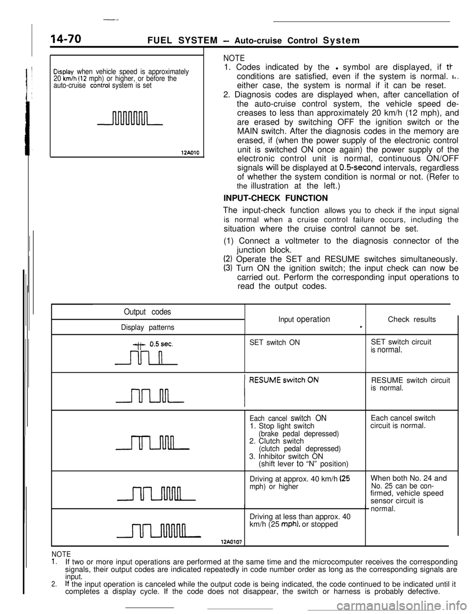
NOTE1. Codes indicated by thel symbol are displayed, if
tt-conditions are satisfied, even if the system is normal.
I,.either case, the system is normal if it can be reset.
2. Diagnosis codes are displayed when, after cancellation of
the auto-cruise control system, the vehicle speed de-
creases to less than approximately 20 km/h (12 mph), and
are erased by switching OFF the ignition switch or the
MAIN switch. After the diagnosis codes in the memory are
erased, if (when the power supply of the electronic control
unit is switched ON once again) the power supply of the
electronic control unit is normal, continuous ON/OFF
signals will be displayed at
O.&second intervals, regardless
of whether the system condition is normal or not. (Refer to
the illustration at the left.)
INPUT-CHECK FUNCTION
The input-check function allows you to check if the input signal
is normal when a cruise control failure occurs, including the
situation where the cruise control cannot be set.
(1) Connect a voltmeter to the diagnosis connector of the
junction block.
(2) Operate the SET and RESUME switches simultaneously.
(3) Turn ON the ignition switch; the input check can now be
carried out. Perform the corresponding input operations to
read the output codes.
Output codes
Display patternsInput
operationCheck resultst
y- 0.5sec.
n
SET switch ONSET switch circuitis normal.RESUME switch circuit
is normal.
Each cancel switch ON1. Stop light switch
(brake pedal depressed)2. Clutch switch
(clutch pedal depressed)3. Inhibitor switch ON
(shift lever to “N” position)Each cancel switch
circuit is normal.
Driving at approx. 40 km/h
(25mph) or higherWhen both No. 24 andNo. 25 can be con-firmed, vehicle speed
sensor circuit is
normal.Driving at less than approx. 40
km/h (25
mph). or stopped
NOTE1.If two or more input operations are performed at the same time and the microcomputer receives the corresponding
signals, their output codes are indicated repeatedly in code number order as long as the corresponding signals are
2.input.If the input operation is canceled while the output code is being indicated, the code continued to be indicated until it
completes a display cycle. If the code does not disappear, the switch or harness is probably defective.
Page 275 of 391
AUTOMATIC TRANSAXLE - Transaxle Control21-51
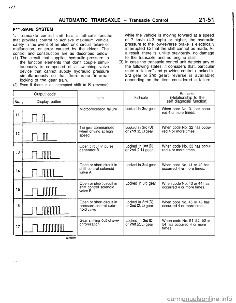
F”“.-SAFE SYSTEM7,
_ transaxle control unit has a fail-safe function
that provides control to achieve maximum vehicle
safety in the event of an electronic circuit failure or
malfunction, or error caused by the driver. The
control and construction are as described below.
(1) The circuit that supplies hydraulic pressure to
the function elements that don’t couple simul-
taneously is composed of a switching valve
device that cannot supply hydraulic pressure
simultaneouslv so that there IS no ‘internal
locking of the gear train.
(2) Even if there is an attempted shift to
Fi (reverse)while the vehicle is moving forward at a speed
of 7 km/h (4.3 mph) or higher, the hydraulic
pressure to the low-reverse brake is electrically
interrupted
SO that the shift cannot be made. Asa result, there is, unlike previously, no damage
to the transaxle and no engine stall.
(3) In case the transaxle control unit detects any of
the following states, it considers that. particular
state a “failure” and provides control (Locked in
3rd gear or 2nd gear; reverse is available)
depending on the item considered a failure.
IOutput code
r- INo.Display pattern
16
ItemFail-safeRemarks(Relationship to the
self diagnosis function)Microprocessor failure
Locked in 3rd gear
When code No. 31 has occur-
red 4 or more
times.
1 st gear commandedwhen driving at high
speedLocked in 3rd (D)or 2nd (2, L) gearWhen code No. 32 has occur-red 4 or more times.
Open circuit in pulse
generator
BLocked in 3rd (D)or 2nd (2, L) gearWhen code No. 33 has occur-red 4 or more times.
Open or short circuit in
shift control solenoid
valve A
Locked in 3rd gear
When code No. 41 or 42 hasoccurred 4 or more times.
Open or short circuit in
shift control solenoid
valve
B
Locked in 3rd gearWhen code No. 43 or 44 has
occurred 4 or more times.
Open or short circuit in
pressure control
sole-noid valve
Locked in 3rd (DIor 2nd (2, L) gearWhen code No. 45 or 46 hasoccurred 4 or more times.
Gear shifting out of syn-Locked in 3rd (D)When code No. 51,52,53 or
chronization
or 2nd (2, L) gear54 has occurred 4 or moretimes
12Ao104
-
Page 276 of 391
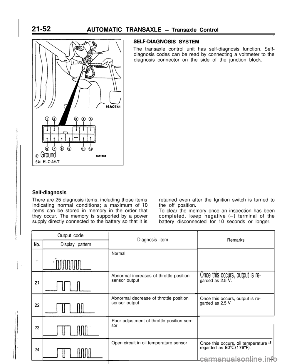
AUTOMATIC TRANSAXLE - Transaxle ControlSELF-DIAGNOStS SYSTEM
The transaxle control unit has self-diagnosis function.
Self-diagnosis codes can be read by connecting a voltmeter to the
diagnosis connector on the side of the junction block.
0: Ground
6%: ELC-MIT
Self-diagnosisThere are 25 diagnosis items, including those items
indicating normal conditions; a maximum of
10items can be stored in memory in the order that
they occur. The memory is supported by a power
supply directly connected to the battery so that it isretained even after the Ignition switch is turned to
the off position.
To clear the memory once an inspection has been
completed. keep negative
(-) terminal of the
battery disconnected for
10 seconds or longer.
r
No.
23
24
Output code
Display pattern
TDiagnosis itemRemarks
NormalAbnormal increases of throttle position
sensor output
Abnormal decrease of throttle position
sensor output
Poor adjustment of throttle position sen-
sorOpen circuit in oil temperature sensor
Once this occurs, output is re-
garded as 2.5 V.Once this occurs, output is re-
garded as 2.5 VOnce this occurs,
oil temperature isregarded as 80°C (176°F).
Page 277 of 391
AUTOMATIC TRANSAXLE - Transaxle Control21-53
I-.
No.-
25Output code
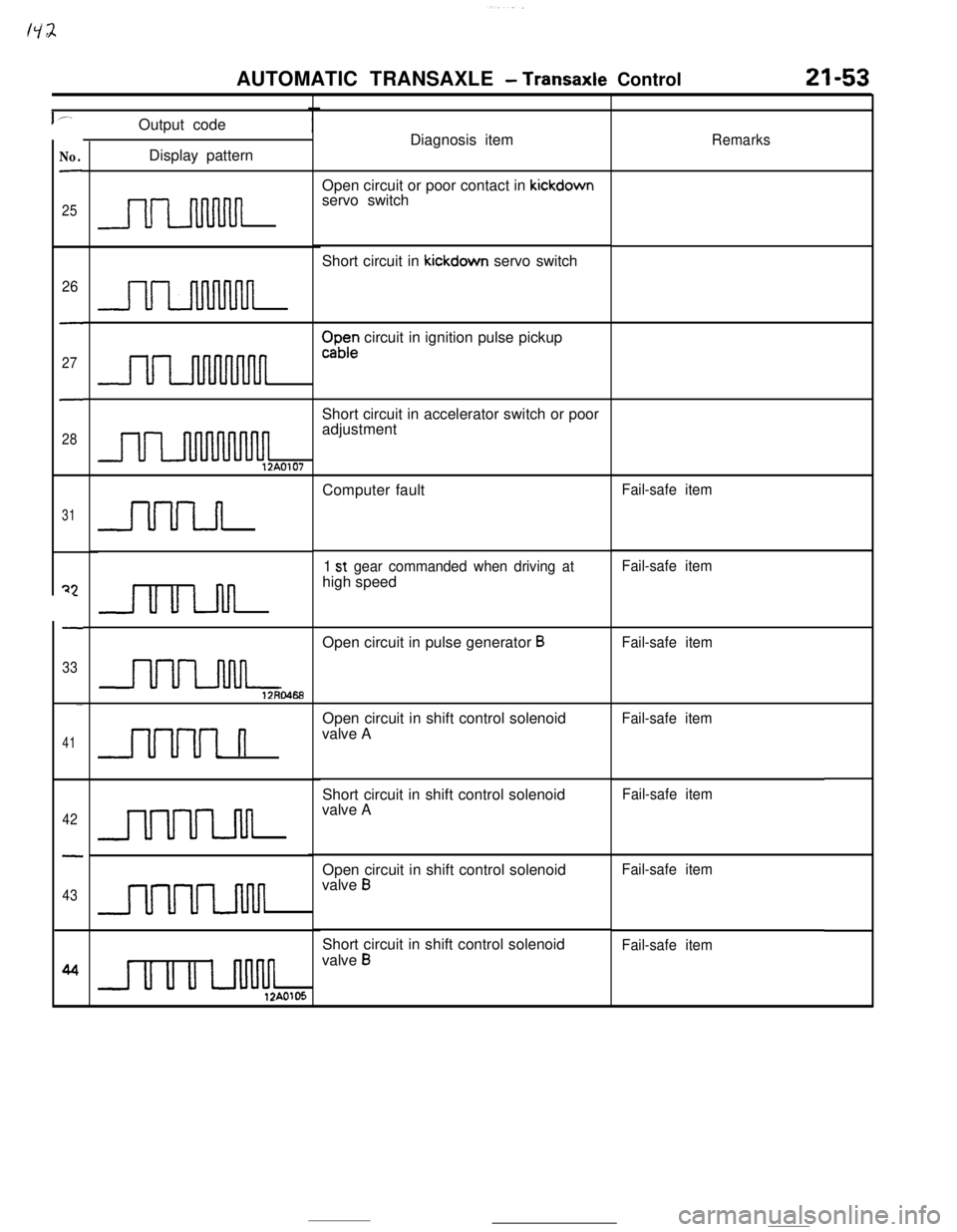
Diagnosis item
RemarksDisplay pattern
Open circuit or poor contact in kickdown
servo switch
IJLluuul~Short circuit in kickdown servo switch
26
-
27
-
28
u1n
CIaD; circuit in ignition pulse pickup
U1Short circuit in accelerator switch or poor
adjustment
UI12A0107
31Computer fault
Fail-safe item
uu-ln
Fail-safe item
1 st gear commanded when driving athigh speed
22
-
33
II u LnnOpen circuit in pulse generator
BFail-safe item
-
41Open circuit in shift control solenoid
valve A
Fail-safe item
nShort circuit in shift control solenoid
valve A
Fail-safe item
42
-
43
UUULMOpen circuit in shift control solenoid
valve
B
Fail-safe item
UULJMShort circuit in shift control solenoid
valve
BFail-safe item
u II II LJM12A0105
Page 278 of 391
-21-54AUTOMATIC TRANSAXLE
- Transaxle Control
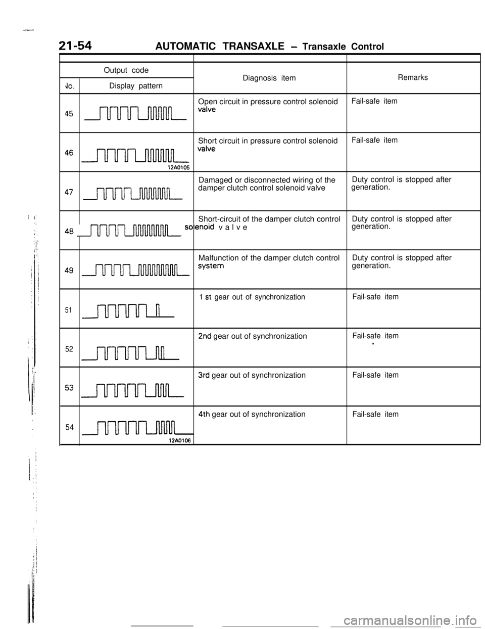
Output code
Diagnosis item
Remarks
JO.Display pattern
Open circuit in pressure control solenoid
Fail-safe item
a5 nnnn valveShort circuit in pressure control solenoid
Fail-safe item
46 m valve12A0105Damaged or disconnected wiring of theDuty control is stopped after
47 nnru7_nnnnnnndamper clutch control solenoid valvegeneration.
Short-circuit of the damper clutch controlDuty control is stopped after
48 m solenord valvegeneration.
Malfunction of the damper clutch controlDuty control is stopped after
49 J- systemgeneration.
1 st gear out of synchronizationFail-safe item
51n
2nd gear out of synchronizationFail-safe iteml52n
3rd gear out of synchronizationFail-safe item
53 m4th gear out of synchronization
Fail-safe item
54
uuum12Ao106