clutch MITSUBISHI ECLIPSE 1990 Workshop Manual
[x] Cancel search | Manufacturer: MITSUBISHI, Model Year: 1990, Model line: ECLIPSE, Model: MITSUBISHI ECLIPSE 1990Pages: 391, PDF Size: 15.27 MB
Page 283 of 391
/ii>--..AUTOMATIC TRANSAXLE
- Transaxle Control21-59
Sxxrolvalve175022E
6
LmeFrom
TooilFrompressure torque- pump 2;0%conver-
termntrd
valveDAMPER CLUTCH CONTROL VALVE AND DAMPER
CLUTCH CONTROL SOLENOID VALVE
Damper Clutch Control Valve
The damper clutch control valve is installed within the lower
valve body; it functions to regulate the hydraulic pressure
acting upon the damper clutch (incorporated within thetorqueconverter).
Damper Clutch Control Solenoid Valve
The damper clutch control solenoid valve is duty-controlled by
the signals from the transaxle control unit; this valve functions
to convert electric signals to hydraulic pressure.
Operation
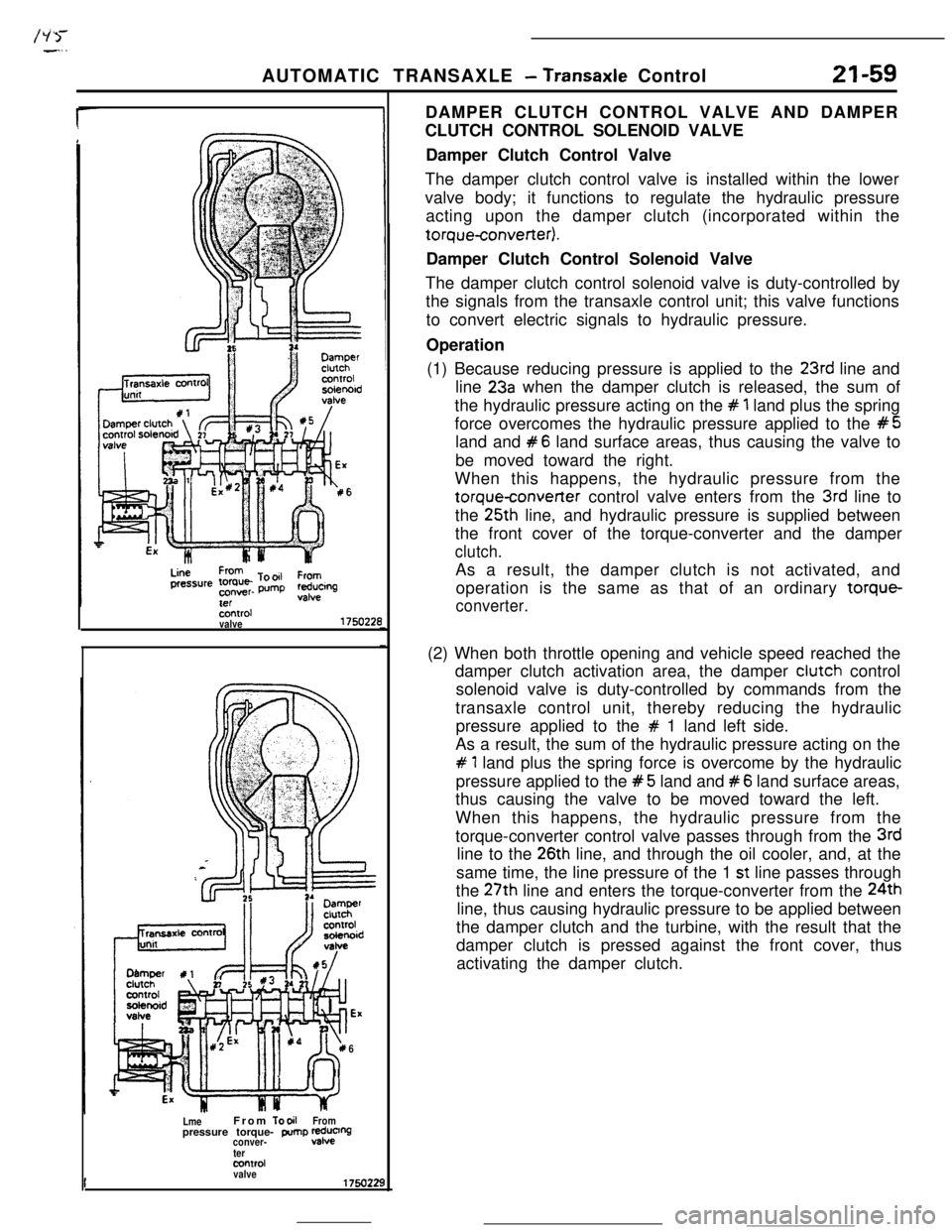
(1) Because reducing pressure is applied to the
23rd line and
line
23a when the damper clutch is released, the sum of
the hydraulic pressure acting on the
# 1 land plus the spring
force overcomes the hydraulic pressure applied to the
#5land and
#6 land surface areas, thus causing the valve to
be moved toward the right.
When this happens, the hydraulic pressure from the
torqueconverter control valve enters from the 3rd line to
the 25th line, and hydraulic pressure is supplied between
the front cover of the torque-converter and the damper
clutch.As a result, the damper clutch is not activated, and
operation is the same as that of an ordinary torque-
converter.(2) When both throttle opening and vehicle speed reached the
damper clutch activation area, the damper clutch control
solenoid valve is duty-controlled by commands from the
transaxle control unit, thereby reducing the hydraulic
pressure applied to the
# 1 land left side.
As a result, the sum of the hydraulic pressure acting on the
# 1 land plus the spring force is overcome by the hydraulic
pressure applied to the
#5 land and #6 land surface areas,
thus causing the valve to be moved toward the left.
When this happens, the hydraulic pressure from the
torque-converter control valve passes through from the
3rdline to the
26th line, and through the oil cooler, and, at the
same time, the line pressure of the 1
st line passes through
the 27th line and enters the torque-converter from the 24th
line, thus causing hydraulic pressure to be applied between
the damper clutch and the turbine, with the result that the
damper clutch is pressed against the front cover, thus
activating the damper clutch.
Page 285 of 391
AUTOMATIC TRANSAXLE - Transaxle Control
.-i:...
21-63To front clutch
Ex ExManual valve
To low/reverse brake
Pressure controlsolenoid valve
1750089
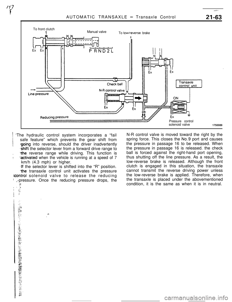
t ‘The hydraulic control system incorporates a “fail1
1safe feature” which prevents the gear shift from
irthe reverse range while driving. This function is
:5activated when the vehicle is running at a speed of 7km/h (4.3 mph) or higher.
;If the selector lever is shifted into the “R” position.
*the transaxle control unit activates the pressure
:control solenoid valve to release the reducing
! ,-pressure. Once the reducing pressure drops, the.-a.rr./ -. jF! ;;1 ;I~N-R control valve is moved toward the right by the
spring force. This closes the No.9 port and causes
the pressure in passage 16 to be released. When
the pressure in passage 16 is released. the check
ball is forced against the right-hand port opening,
thus shutting off the line pressure. As a result, the
low-reverse brake is released. Although the front
clutch is engaged in this situation, the transaxle
cannot transmit the reverse driving power unless
the low-reverse brake is applied. Therefore, when
the transaxle is placed under the abovementioned
condition, it is the same as when it is in neutral.
c
Page 287 of 391
AUTOMATIC TRANSAXLE - Transaxle Control21-65Shift contra
solenoid val
Shift control valve
To N-Dcontrol valve
To rearclutch
t
Line pressure
-1750231
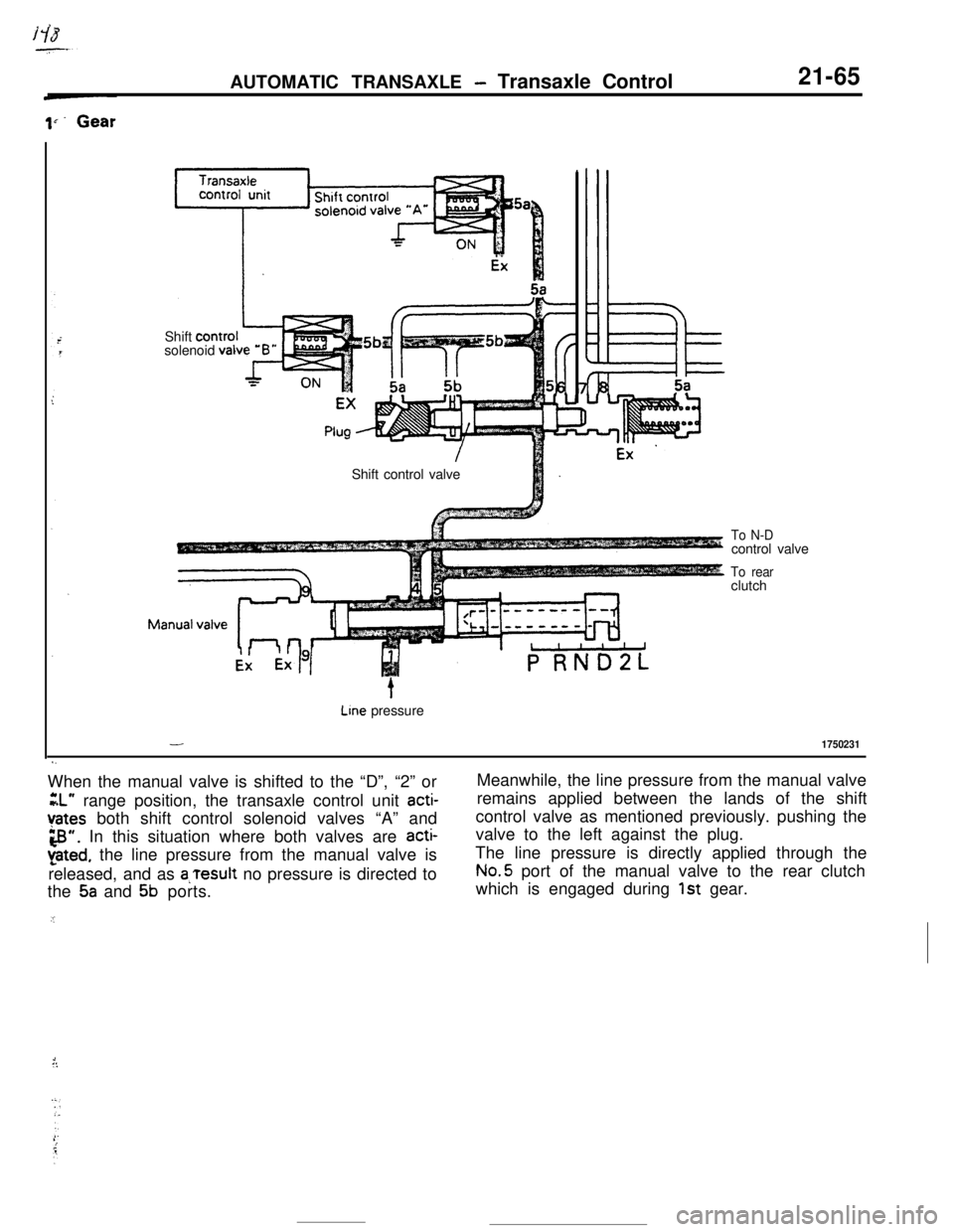
s.When the manual valve is shifted to the “D”, “2” or
GL” range position, the transaxle control unit acti-
Yates both shift control solenoid valves “A” and
3”. In this situation where both valves are acti-
pted, the line pressure from the manual valve is
released, and as
a,Tesult no pressure is directed to
the
5a and 5b ports.
.IMeanwhile, the line pressure from the manual valve
remains applied between the lands of the shift
control valve as mentioned previously. pushing the
valve to the left against the plug.
The line pressure is directly applied through theNo.5 port of the manual valve to the rear clutch
which is engaged during
1st gear.
1::
Page 288 of 391
/
1. .)
21-66
2nd GearAUTOMATIC TRANSAXLE
- Transaxie Control
Plug ’
- 2nd pressure‘:“,,tol, 2 shift
Stopper
To N-Dcontrol valve
To rearclutch -.
Line pressure
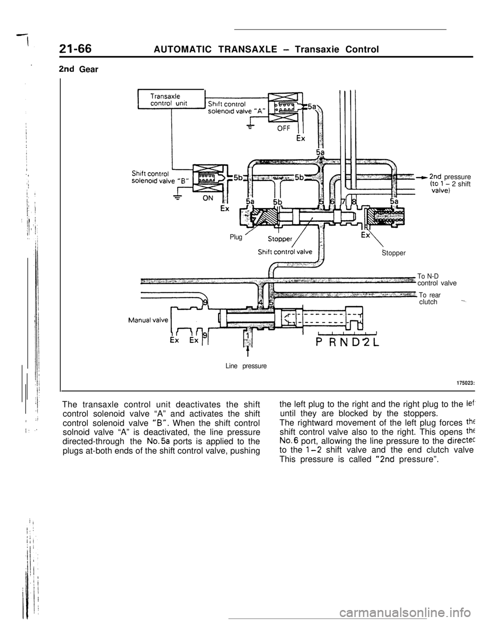
175023:The transaxle control unit deactivates the shift
control solenoid valve “A” and activates the shift
control solenoid valve
“B”. When the shift control
solnoid valve “A” is deactivated, the line pressure
directed-through the
No.5a ports is applied to the
plugs at-both ends of the shift control valve, pushingthe left plug to the right and the right plug to the
lef’until they are blocked by the stoppers.
The rightward movement of the left plug forces
theshift control valve also to the right. This opens
theNo.6 port, allowing the line pressure to the
directecto the
l-2 shift valve and the end clutch valve
This pressure is called
“2nd pressure”.
Page 289 of 391
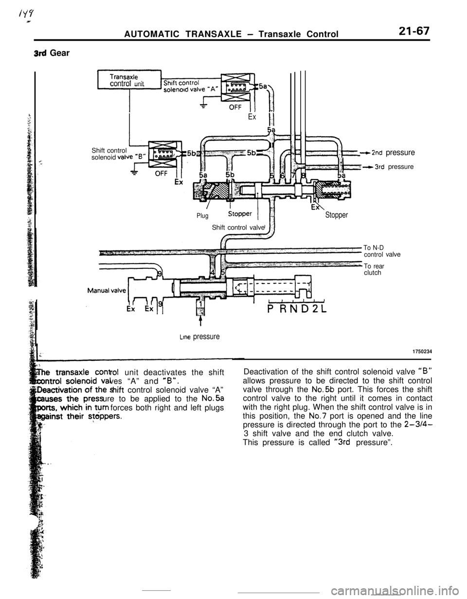
3rd GearAUTOMATIC TRANSAXLE
- Transaxle Control21-67
control unitShift control
solenoid
vail
ExII5a
PlugShift control valve
‘F$&‘- - 2nd pressure
wkh- 3rd pressure
Stopper
Line pressure
rolunit deactivates the shift
ves“A” and “B”.hift control solenoid valve “A”
ure to be applied to the No.5a
forces both right and left plugs
To N-D
control
To rearclutchvalve
1750234Deactivation of the shift control solenoid valve
“B”allows pressure to be directed to the shift control
valve through the No.5b port. This forces the shift
control valve to the right until it comes in contact
with the right plug. When the shift control valve is in
this position, the No.7 port is opened and the line
pressure is directed through the port to the
2-3/4-3 shift valve and the end clutch valve.
This pressure is called
“3rd pressure”.
Page 290 of 391
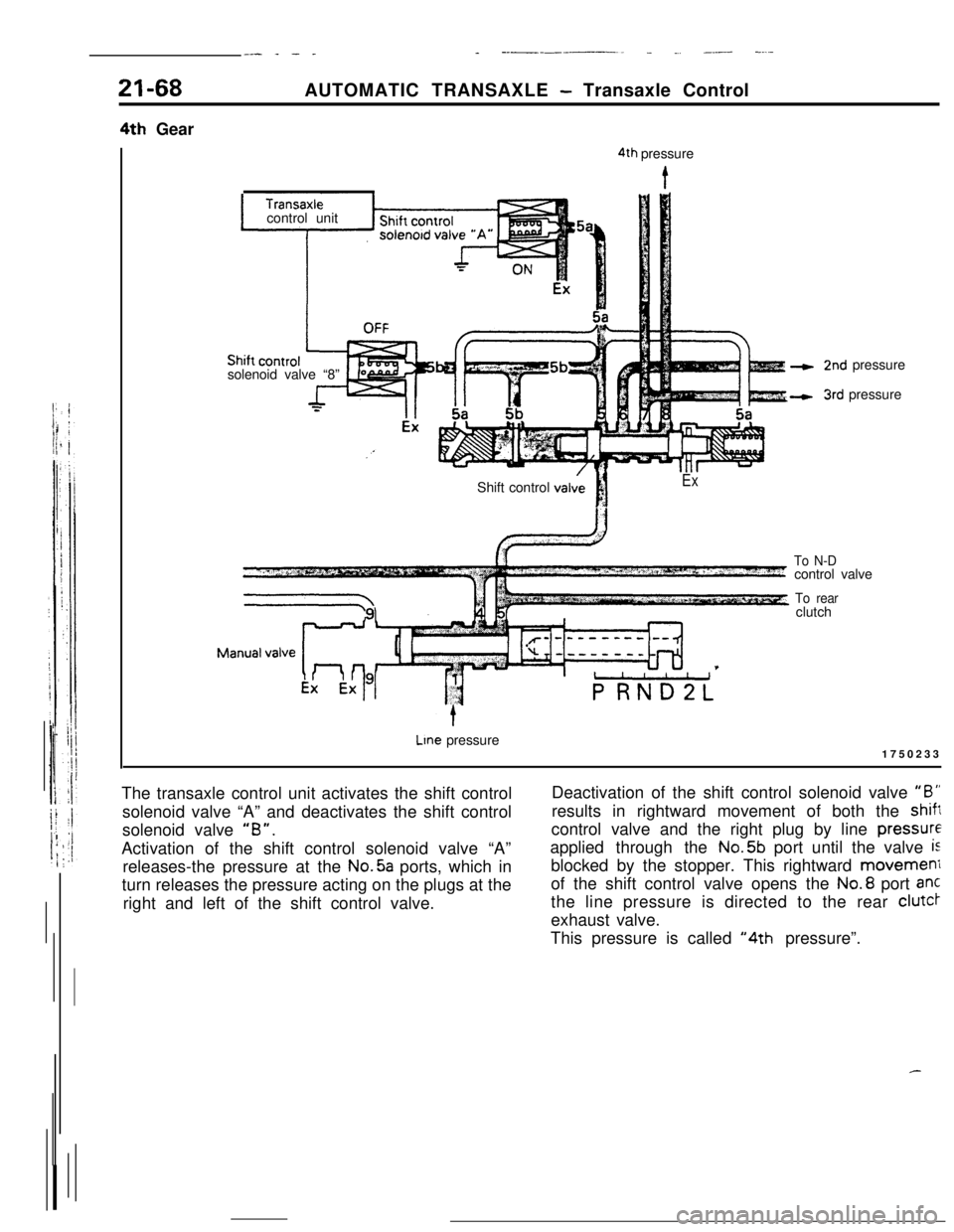
__- _ - __ ----____. _ ., _.- -....21-684th GearAUTOMATIC TRANSAXLE
- Transaxle Control
solenoid valve “8”
4th pressure
Icontrol unit
2nd pressure
3rd pressure
Shift control
valviI!
iEx
To N-Dcontrol valve
To rearclutch
Lme pressure
1750233
The transaxle control unit activates the shift control
solenoid valve “A” and deactivates the shift control
solenoid valve
“B”.Activation of the shift control solenoid valve “A”
releases-the pressure at the No.5a ports, which in
turn releases the pressure acting on the plugs at the
right and left of the shift control valve.Deactivation of the shift control solenoid valve
“B”results in rightward movement of both the
shiftcontrol valve and the right plug by line
pressureapplied through the No.5b port until the valve
isblocked by the stopper. This rightward movemeni
of the shift control valve opens the No.8 port ant
the line pressure is directed to the rear clutcr
exhaust valve.
This pressure is called
“4th pressure”.
Page 291 of 391
/gi--__ .--.-9
Reducingvalve
To kickdown
servo via 1 - 2
shift valveLine pressureAUTOMATIC TRANSAXLE
- Transaxle Control21-69
PRESSURE CONTROL VALVE, SOLENOID
-_ VALVE AND N-R CONTROL VALVE
: Pressure Control Valve
: This valve regulates the pressure supplied to each
clutch under the control of the pressure control
j.. solenoid<,A ,valve to eliminate shock at the time ofPressure Control Solenoid Valve
This valve has its duty controlled by the transaxlecontrol unit command. It changes an electric com-
mand to corresponding hydraulic pressure.
N-R Control Valve
This valve prevents shock from occurring when the
select lever is shifted from “N” to
“R” (or from “P”
to
“R”) by controlling the oil pressure applied to the
low-reverse brake..Stopping (Selector lever in
“D” or “2”)
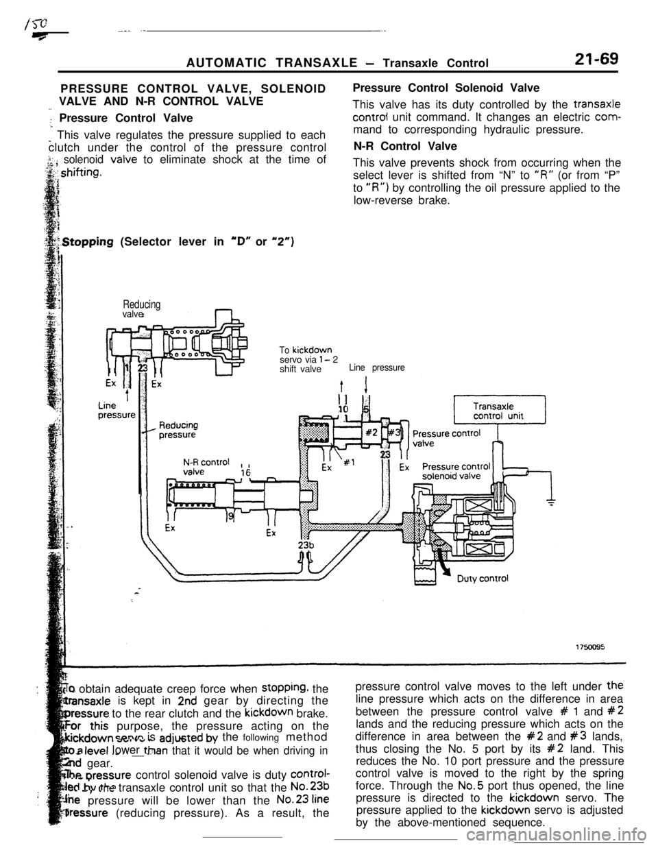
‘r) obtain adequate creep force when stopping, the
is kept in
2nd gear by directing the
to the rear clutch and the kickdown brake.
purpose, the pressure acting on the
=nnm is adjusted by the following method
- .--v.._ _ _ __ --Tan that it would be when driving in
..d gear.
he nrennurecontrol solenoid valve is duty control-
..s,. ..Jtransaxle control unit so that the No.231..a
pressure will be lower than the No.23
fine
bressure (reducing pressure). As a result, the
level lower ttlpressure control valve moves to the left under the
line pressure which acts on the difference in area
between the pressure control valve
# 1 and #2lands and the reducing pressure which acts on the
difference in area between the
#2 and #3 lands,
thus closing the No. 5 port by its
#2 land. This
reduces the No. 10 port pressure and the pressure
control valve is moved to the right by the spring
force. Through the No.5 port thus opened, the line
pressure is directed to the kickdown servo. The
pressure applied to the kickdown servo is adjusted
by the above-mentioned sequence.
-
Page 293 of 391
AUTOMATIC TRANSAXLE - Transaxle Control21-71
‘ift (Selector Lever in “D” or “2”)
ReducingLine
ipressureTo kickdown servo
or from clutch
via3H
l-r
I
1 - 2 shift valve
Line pressure
Ext 1II ”i1
Reducingpressure
N-R control,,
II& Pressure control
solenoid valve
b-l
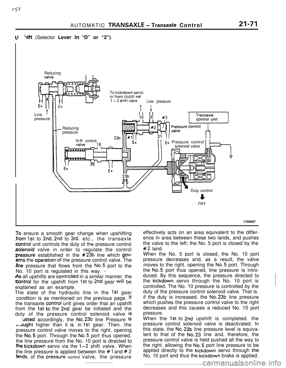
To ensure a smooth gear change when upshifting
:from 1st to 2nd, 2nd to 3rd. etc., the transaxle
lcontrol unit controls the duty of the pressure control
z$olenoid valve in order to regulate the control‘pressure established in the
#23b line which gov-
‘ems the operationof the pressure control valve. The
Jlne pressure that flows from the No.5 port to the
No. 10 port is regulated in this way.
-
i& all upshifts are controlied in a similar manner. the
icontrol for the upshift from 1st to 2nd gear will be
explained as an example.
The state of the hydraulic line in the
1st gear
condition is as mentioned on the previous page.
Ifthe transaxle control unit gives order that an upshift
from the
1st to the 2nd gear be initiated and the
duty of the pressure control solenoid valve
is‘usted accordingly, the No.23b line Pressure
is
-.dught higher than it is. in 1st gear. Then. the
pressure control valve moves to the right, opening
the No.5 port. Through the
No.5 port thus opened.
the line pressure from the No. 10 port is directed to
the kickdown servo via the l-2 shift valve. When
the line pressure is applied between the
# 1 and # 2
lands. of the rxessure control valve, the pressureDuty control
+OFF
1750097
effectively acts on an area equivalent to the differ-
ence in area between these two lands, and pushes
the valve to the left; the No. 5 port is closed by the
#2 land.
When the No. 5 port is closed, the No. 10 port
pressure decreases and, as a result, the valve
moves to the right. opening the No.5 port. Through
the No.5 port thus opened, line pressure is intro-
duced. By this sequence, the pressure directed to
the kickdown servo through the No. 10 port is
controlled. The No. 10 pressure is controlled by the
duty of the pressure control solenoid valve. That is.
if the duty is increased, the No.23b line pressure
which pushes the pressure control valve to the right
decreases and this causes a reduced No. 10 port
pressure.When the
1st to 2nd upshift is completed. the
pressure control solenoid valve is deactivated. In
this state, the No.23b line pressure level is equiva-
lent to that of the No.23 line and, therefore, the
pressure control valve is held pushed all the way to
the right. allowing the No.5 port line pressure to be
applied directly to the kickdown servo through the
No. 10 port and thus the kickdown brake is applied.
Page 298 of 391
?
I
21-76AUTOMATIC TRANSAXLE - Transaxle Control
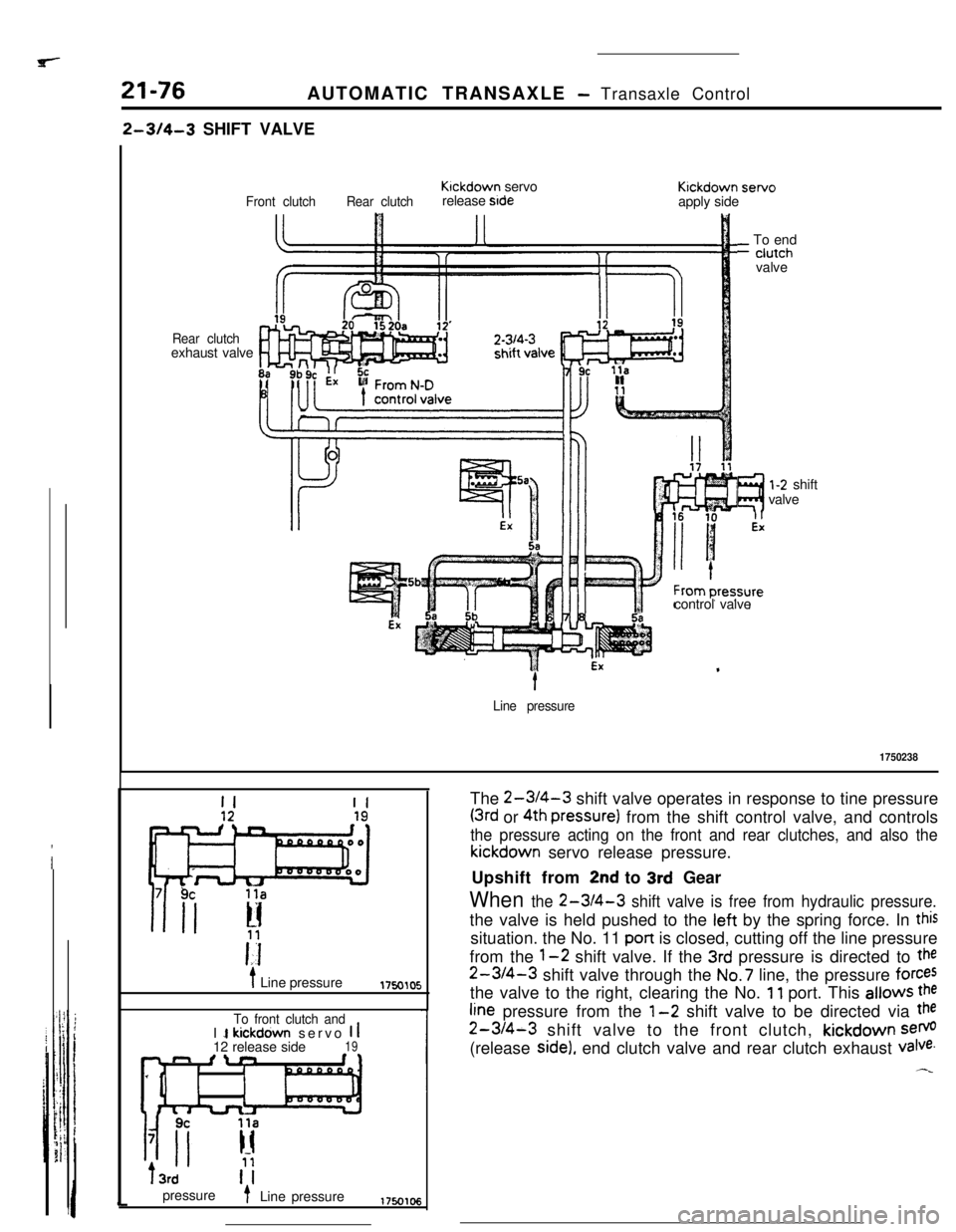
2-314-3 SHIFT VALVE
Rear clutchexhaust valve
Front clutchRear clutchKlckdown servo
release stdeKickdown servo
apply side
?I
l-2 shift
valve
control valve
_ To end- ciutch
valvet
Line pressure
1750238
II
i Line pressure1750105
To front clutch andI 1 kickdown servo 1 112 release side19n fln
IIT3rd
pressure
t- Line pressureThe
2-WI-3 shift valve operates in response to tine pressure
(3rd or 4th pressure) from the shift control valve, and controls
the pressure acting on the front and rear clutches, and also thekickdown servo release pressure.
Upshift from
2nd to 3rd Gear
When the 2-3/4-3 shift valve is free from hydraulic pressure.the valve is held pushed to the left by the spring force. In
thissituation. the No. 11 pan is closed, cutting off the line pressure
from the
1-2 shift valve. If the 3rd pressure is directed to the
2-3/4-3 shift valve through the No.7 line, the pressure forcesthe valve to the right, clearing the No.
11 port. This allows the
fine pressure from the l-2 shift valve to be directed via the
2-3/4-3 shift valve to the front clutch, kickdown sem(release
side), end clutch valve and rear clutch exhaust valve.
Page 299 of 391
![MITSUBISHI ECLIPSE 1990 Workshop Manual ir yAUTOMATIC TRANSAXLE
- Trahsaxle Control21-774th Gear
3rd GearRear clutchKickdown
1servo
release sideFront clutch
-
Rear clutch3rd1-2 shiftKickdown
Front clutch
q]b Ture,‘r z&eside
7
1750107
1F MITSUBISHI ECLIPSE 1990 Workshop Manual ir yAUTOMATIC TRANSAXLE
- Trahsaxle Control21-774th Gear
3rd GearRear clutchKickdown
1servo
release sideFront clutch
-
Rear clutch3rd1-2 shiftKickdown
Front clutch
q]b Ture,‘r z&eside
7
1750107
1F](/img/19/57103/w960_57103-298.png)
ir yAUTOMATIC TRANSAXLE
- Trahsaxle Control21-774th Gear
3rd GearRear clutchKickdown
1servo
release sideFront clutch
-
Rear clutch3rd1-2 shiftKickdown
Front clutch
q]b Ture,‘r z&eside
7
1750107
1Fromk-D3rd 14th pressure
control valve1 ;l;hiftpressure1750108
Upshift from
3rd to 4th Gear
.When the 4th pressure (line pressure) from the shift
control valve is directed to the rear clutch exhaust
valve through the No.8 line. the valve is pushed to
the right, closing the No.5c port. This cuts off the
pressure to the rear clutch and also releases the
pressure acting on the rear clutch through NO.
15port, No.20a port and No. 20
port.On the other hand, the rear clutch exhaust
valvewhich is pushed to the right opens the NO. 19
POnand directs the 4th pressure (line pressure) to the
right end of the
2-3/4-3 shift valve. The 3rdpressure (or the No.7 line pressure) is acting on theleft
end of the 2-3/4-3 shift valve. As this Pressure
..is equal to the No. 19 line pressure and acts on the
Mme area, the spring at the right end of the valveWhen the 4th pressure is released by the move-
ment of the shift control valve, the rear clutchDownshift from 4th to
3rd Gear
exhaust valve moves to the left, creating a
3rd gearstate, and the pressure is directed to the rear clutch.
At the same time as this happens, the 4th pressure
in No. 19 line which has been acting on the 2-3/4-3shift valve is released. This causes the
3rd pressure
established in the
No.7 line to push the 2-3/4-3shift valve to the right, and creates a 3rd gear state
where the line pressure from the
l-2 shift valve is
directed to the front clutch and the release side
chamber of kickdown servo cylinder through the
No. 12 line.shes the valve toward the
left. closing the No. 11me pressure port. This
btocks the pressure to the
front clutch and the release side chamber ofkickdown servo cylinder, and the pressure is re-
leased through the No. 12. and then the
No.9~ Pofi.