dimensions MITSUBISHI ECLIPSE 1990 Service Manual
[x] Cancel search | Manufacturer: MITSUBISHI, Model Year: 1990, Model line: ECLIPSE, Model: MITSUBISHI ECLIPSE 1990Pages: 391, PDF Size: 15.27 MB
Page 17 of 391

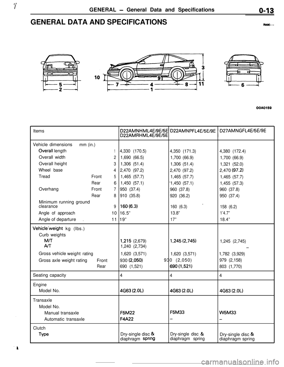
GENERAL - General Data and Specificationso-13GENERAL DATA AND SPECIFICATIONS
M...
OOAO159Items
Vehicle dimensions
mm (in.)
Overall length14,330 (170.5)
4,350 (171.3)4,380 (172.4)Overall width
21,690 (66.5)
1,700 (66.9)
1,700 (66.9)Overall height
31,306 (51.4)
1,306 (51.4)
1,321 (52.0)
Wheel base
42,470 (97.2)
2,470 (97.2)2,470
(97.2)
Tread
Front51,465 (57.7)
1,465 (57.7)
1,465 (57.7)
Rear61,450 (57.1)
‘1,450 (57.1)
1,455 (57.3)Overhang
Front7950 (37.4)
960 (37.8)960 (37.8)
Rear
8910 (35.8)
920 (36.2)950 (37.4)Minimum running ground
’clearance9lsO(6.3)160 (6.3)
158 (6.2)
Angle of approach10 16.5”13.8”1’4.7”Angle of departure
11 19”
17”18.4”.Vehicle’weight kg (Ibs.)
Curb weightsM/T
1,215 (2,679)1.245.(2,745)
1,245 (2,745)
Al-r
1,240 (2,734)-Gross vehicle
weight
rating
1,620 (3,571)
1,620 (3,571)1,782 (3,929)Gross axle weight rating
Front930
(2.050)930 (2,050)979 (2,158)
Rear690 (1,521)690(1,521)803 (1,770)Seating capacity
4
44
EngineModel No.
4663 (2.OL)4663 (2.OL)4663 (2.OL)
TransaxleModel No.
Manual transaxleF5M22F5M33
W5M33Automatic transaxle
F4A22--
Clutch
TypeDry-single disc &Dry-single disc &
Dry-single disc &
diaphragm spnngdiaphragm springdiaphragm spring
Page 30 of 391

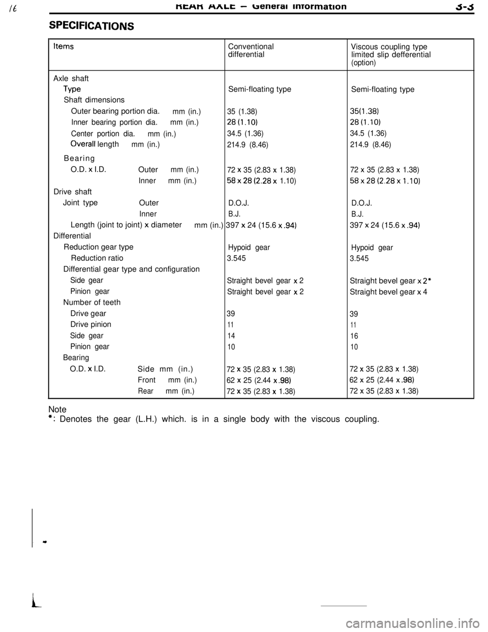
SPECIFICATIONSMEHM
nnlL -ueneral mrormationJ-JItemsConventional
differentialViscous coupling type
limited slip defferential
(option)Axle shaft
TypeSemi-floating type
Shaft dimensions
Outer bearing portion dia.
mm (in.)35 (1.38)
Inner bearing portion dia.mm (in.)28t1.10)
Center portion dia.
mm (in.)34.5 (1.36)
Overall lengthmm (in.)
214.9 (8.46)Bearing
O.D. x I.D.
Outer
mm (in.)
72 x 35 (2.83 x 1.38)
Innermm (in.)
58x28(2.28x 1.10)Drive shaft
Joint type
Outer
D.O.J.
Inner
B.J.Length (joint to joint)
x diameter
mm (in.) 397 x 24 (15.6 x .94)Differential
Reduction gear type
Hypoid gearReduction ratio
3.545Differential gear type and configuration
Side gear
Straight bevel gear x 2
Pinion gear
Straight bevel gear x
2Number of teeth
Drive gear
39Drive pinion
11
Side gear14
Pinion gear10
BearingO.D.
x I.D.
Side mm (in.)72 x 35 (2.83 x 1.38)
Frontmm (in.)
62 x
25 (2.44 x .98)
Rearmm (in.)
72 x 35 (2.83 x 1.38)NoteSemi-floating type
35f1.38)28t1.10)
34.5 (1.36)
214.9 (8.46)
72
x 35 (2.83 x 1.38)
58x28(2.28x1.10)
D.O.J.
B.J.397 x 24 (15.6 x
.94)
Hypoid gear
3.545Straight bevel gear x
2”Straight bevel gear x 4
39
11
16
10
72 x 35 (2.83 x 1.38)
62
x 25 (2.44 x .98)
72 x 35 (2.83 x 1.38)
*: Denotes the gear (L.H.) which. is in a single body with the viscous coupling.
i
Page 332 of 391

BODY - Main Body23-15MAINTENANCE SERVICEABILITY
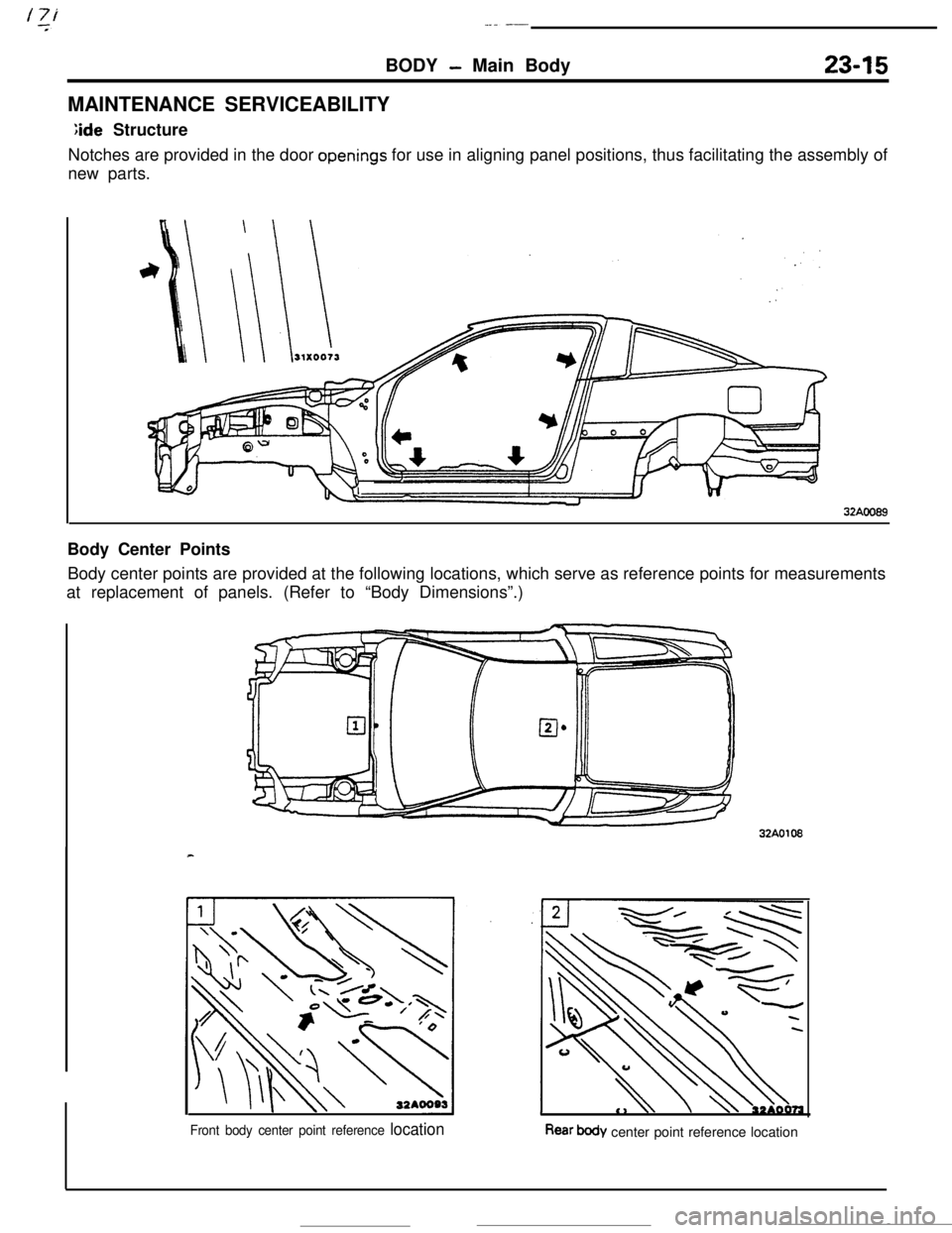
;ide Structure
Notches are provided in the door
openings for use in aligning panel positions, thus facilitating the assembly of
new parts.
32AOO89Body Center Points
Body center points are provided at the following locations, which serve as reference points for measurements
at replacement of panels. (Refer to “Body Dimensions”.)32A0108
Front body center point reference locationRear body center point reference location