battery MITSUBISHI ECLIPSE 1990 Service Manual
[x] Cancel search | Manufacturer: MITSUBISHI, Model Year: 1990, Model line: ECLIPSE, Model: MITSUBISHI ECLIPSE 1990Pages: 391, PDF Size: 15.27 MB
Page 55 of 391
ELECTRICAL - Fuses8-3q
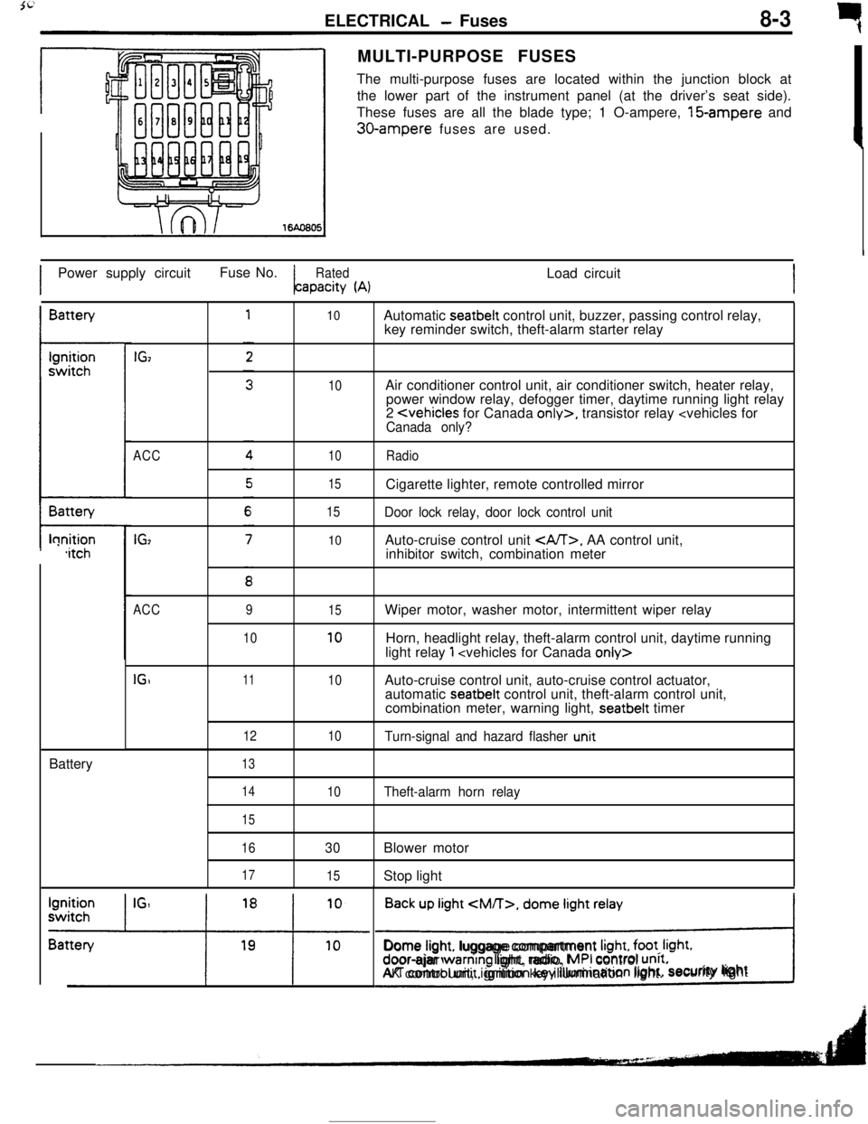
rMULTI-PURPOSE FUSES
The multi-purpose fuses are located within the junction block at
the lower part of the instrument panel (at the driver’s seat side).
These fuses are all the blade type; 1 O-ampere, 15-ampere and
30-ampere fuses are used.
IPower supply circuitFuse No.
RatedLoad circuitapacity
(A)IBattery
t-lonition,itchBattery
IGz
ACC
IG,
10
10
10
15
15
10Automatic seatbelt control unit, buzzer, passing control relay,
key reminder switch, theft-alarm starter relay
Air conditioner control unit, air conditioner switch, heater relay,
power window relay, defogger timer, daytime running light relay
2
Door lock relay, door lock control unitAuto-cruise control unit
, AA control unit,
inhibitor switch, combination meter
ACC
IGI9
1011
12
1315
10
10
10Wiper motor, washer motor, intermittent wiper relay
Horn, headlight relay, theft-alarm control unit, daytime running
light relay
1
automatic seatbelt control unit, theft-alarm control unit,
combination meter, warning light, seatbelt timer
Turn-signal and hazard flasher u.nit
14
15
16
17
10Theft-alarm horn relay
30Blower motor
15Stop light
Back up light
CM/T>, dome light relay
!Dome light. luggage compartment
Irght, foot. Irght.door-ajar warntng light, radio, MPI control unrt.AK control unit, ignition key illumination light.security lightI
Page 69 of 391
ELECTRICAL - Lighting8-17
Front turnsignal light
(Optical horn)
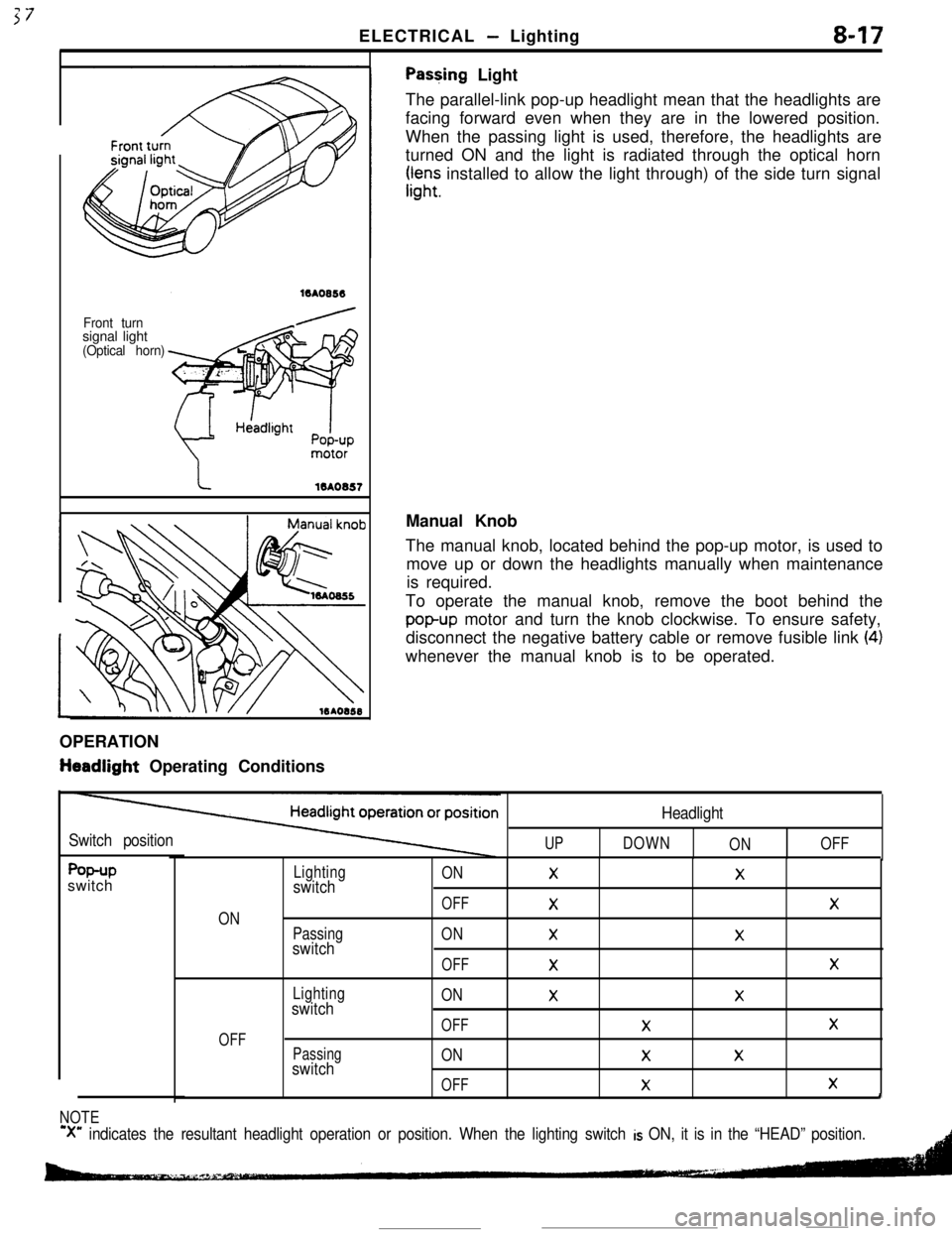
Pas+ing Light
The parallel-link pop-up headlight mean that the headlights are
facing forward even when they are in the lowered position.
When the passing light is used, therefore, the headlights are
turned ON and the light is radiated through the optical horn
rr,“;; installed to allow the light through) of the side turn signal
OPERATION
tieadlight Operating ConditionsManual Knob
The manual knob, located behind the pop-up motor, is used to
move up or down the headlights manually when maintenance
is required.
To operate the manual knob, remove the boot behind the
popup motor and turn the knob clockwise. To ensure safety,
disconnect the negative battery cable or remove fusible link
(4)whenever the manual knob is to be operated.
Switch positionUP
Headlight
DOWN
ONOFF
f%+Pswitch
ON
OFF
Lightingswitch
Passingswitch
Lightingswitch
Passingswitch
ONXX
OFF
XX
ONXX
OFF
XX
ONXX
OFFXX
ONXX
OFF
XXI
NOTE
‘X” indicates the resultant headlight operation or position. When the lighting switch is ON, it is in the “HEAD” position.
Page 74 of 391
8-22ELECTRICAL - Lighting--Ignition ON
switch OFF
prDoor ON
switch OFF
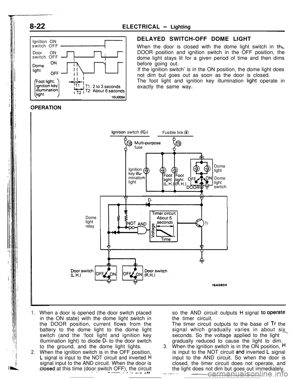
IDELAYED SWITCH-OFF DOME LIGHT
When the door is closed with the dome light switch in
thtDOOR position and ignition switch in the OFF position, the
dome light stays lit for a given period of time and then dims
before going out.
If the ignition switch’ is in the ON position, the dome light does
not dim but goes out as soon as the door is closed.
The foot light and ignition key illumination light operate in
exactly the same way.
16UOO94OPERATIONIgnition switch
(G)Fusible link a
Domelight
relay
9 Mutti-purpose
fuse
%69Ignition
key illu-
minatio
light
Domelight
Domelight
switch
Tr
;:16AO604
1.When a door is opened (the door switch placed
in the ON state) with the dome light switch in
the DOOR position, current flows from the
battery to the dome light to the dome light
switch (and the ‘foot light and ignition key
illumination light) to diode
DI to the door switch
to the ground, and the dome light lights.
2.When the ignition switch is in the OFF position,
L signal is input to the NOT circuit and inverted Hsignal input to the AND circuit. When the door is
-closed at this time (door switch OFF), the circuit
. .----es :- _.a -&Aso the AND circuit outputs
H signal to operate
the timer circuit.
The timer circuit outputs to the base of
Tr the
signal which gradually varies in about six
seconds. So the voltage applied to the light
-gradually reduced to cause the light to dim.
3.When the ignition switch is in the ON position,His input to the NOT circuit
ahd inverted L signal
input to the AND circuit. So when the door is
closed, the timer circuit does not operate, and
the light does not dim but goes out immediately.
_- .-._. ._-__._
Page 75 of 391
ELECTRICAL- Ermine Electrical8-23
ENGINE ELECTRICALRoaGAABALTERNATOR
L terminal\Stern
Electronicvoltage regulator
B terminal/
Rectlfber‘i ‘IT
VFantl
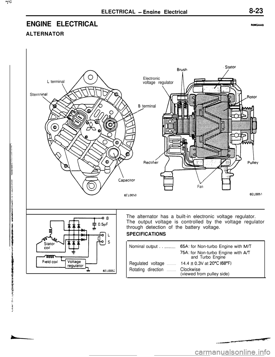
GEL0051The alternator has a built-in electronic voltage regulator.
The output voltage is controlled by the voltage regulator
through detection of the battery voltage.
SPECIFICATIONS
Nominal output . . .._...._..65A: for Non-turbo Engine with M/T
75A: for Non-turbo Engine with AAand Turbo Engine
Regulated voltage. . . . . . . .14.4 f 0.3V at 20°C (68°F)
Rotating direction. . . . . . . .Clockwise(viewed from pulley side)
-
Page 77 of 391
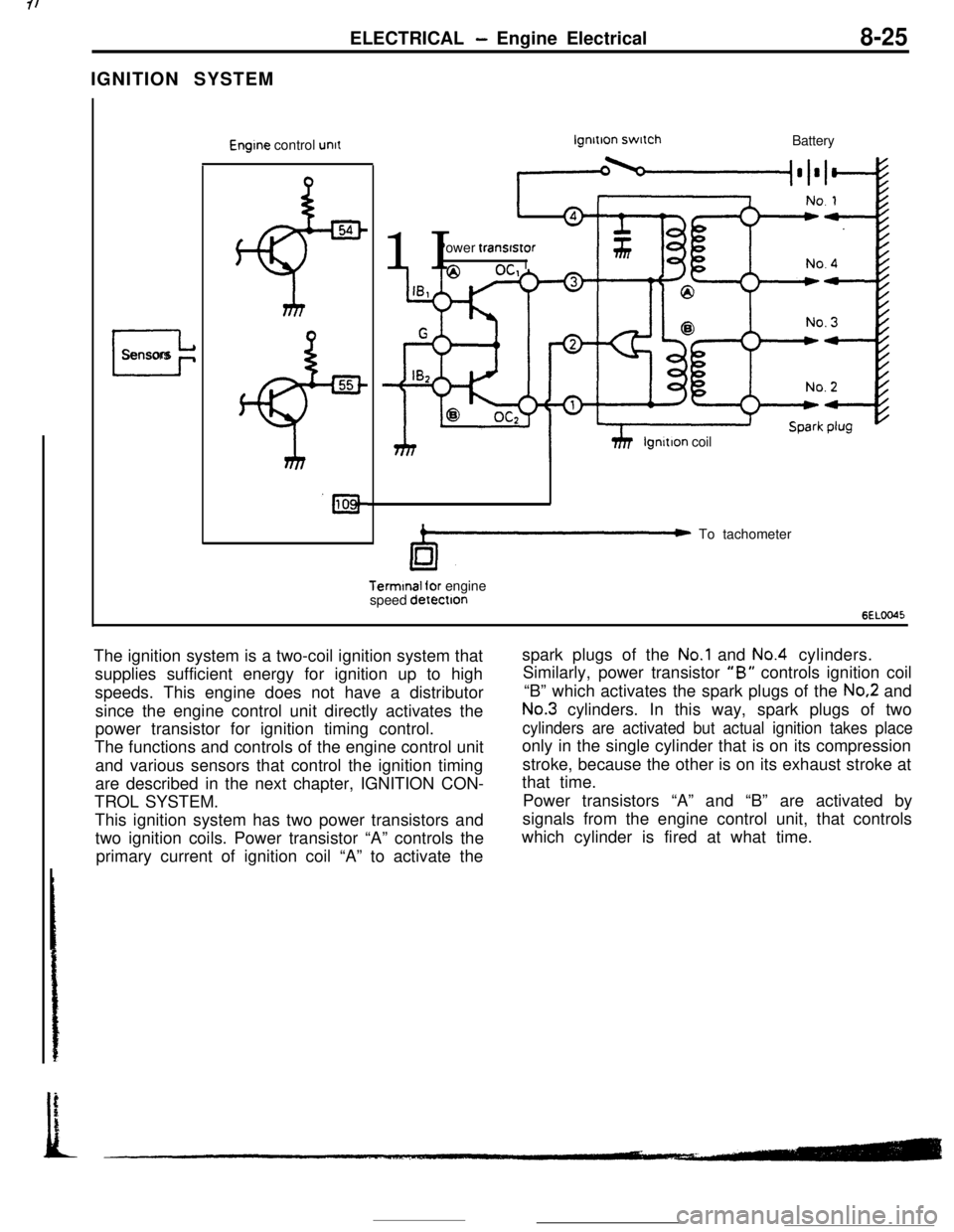
IGNITION SYSTEMELECTRICAL - Engine Electrical8-25
I
Sensors
Engine control unitlgnltlon switch
Battery
11 IPower transfstor
hhP 1
Ilgnltion coil
C To tachometerTerminal for engine
speed detectton
6ELOO45The ignition system is a two-coil ignition system that
supplies sufficient energy for ignition up to high
speeds. This engine does not have a distributor
since the engine control unit directly activates the
power transistor for ignition timing control.
The functions and controls of the engine control unit
and various sensors that control the ignition timing
are described in the next chapter, IGNITION CON-
TROL SYSTEM.
This ignition system has two power transistors and
two ignition coils. Power transistor “A” controls the
primary current of ignition coil “A” to activate thespark plugs of the
No.1 and No.4 cylinders.
Similarly, power transistor
“B” controls ignition coil
“B” which activates the spark plugs of the
No.2 and
No.3 cylinders. In this way, spark plugs of two
cylinders are activated but actual ignition takes placeonly in the single cylinder that is on its compression
stroke, because the other is on its exhaust stroke at
that time.
Power transistors “A” and “B” are activated by
signals from the engine control unit, that controls
which cylinder is fired at what time.
Page 83 of 391
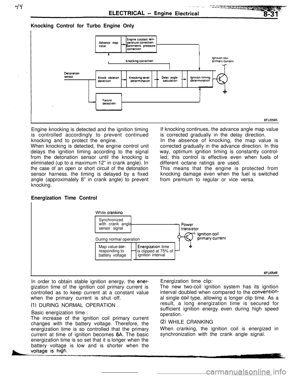
Knocking Control for Turbo Engine OnlyEngine coolant tern.Advance mapperarure correctton
value- Barometric pressurecorrectton
DelonaIlon
sensorI
lgnmon codKnockmg correcllonprimary currenr
v
Knock wbral+onKnockmg LevelDelay anglelgnmon tlmtngdetemon- delermonmon - calculallon - derermmatlon
II
Y
FatlureIdeIeclton
6FUO565Engine knocking is detected and the ignition timing
is controlled accordingly to prevent continued
knocking and to protect the engine.
When knocking is detected, the engine control unit
delays the ignition timing according to the signal
from the detonation sensor until the knocking is
eliminated (up to a maximum 12” in crank angle). In
the case of an open or short circuit of the detonationsensor harness. the timing is delayed by a fixed
angle (approximately 8” in crank angle) to prevent
knocking.Energization Time Control
While
crankinaIf knocking continues, the advance angle map value
is corrected gradually in the delay direction.
In the absence of knocking, the map value is
corrected gradually in the advance direction. In this
way, optimum ignition timing is constantly control-
led; this control is effective even when fuels of
different octane ratings are used.
This means that the engine is protected from
knocking damage even when the fuel is switched
from premium to regular or vice versa.
Synchronizedwith crank angle
sensor signalcDuring normal operation
Map value
cor-Energizatlon time
responding to- is clipped at 75% of
battery voltageignition interval
IIn order to obtain stable ignition energy, the
ener-gization time of the ignition coil primary current is
controlled as to keep current at a constant value
when the primary current is shut off.
(1) DURING NORMAL OPERATION
Basic energization time
:The increase of the ignition coil primary current
changes with the battery voltage. Therefore, the
energization time is so controlled that the primary
current at time of ignition becomes
6A. The basic
energization time is so set that it is longer when the
battery voltage is low and is shorter when the
6FUO548Energization time clip:
The new two-coil ignition system has its ignition
interval doubled when compared to the convention-
al single
coil type, allowing a longer clip time. As a
result, a long energization time is secured for
sufficient ignition energy even during high speed
operation.
(2) WHILE CRANKING
When cranking, the ignition coil is energized in
synchronization with the crank angle signal.
-
Page 123 of 391
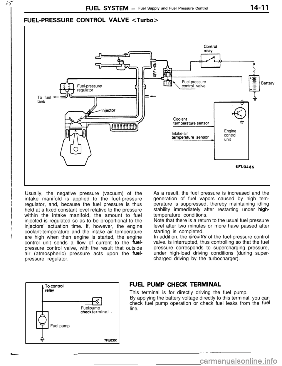
FUEL SYSTEM -Fuel Supply and Fuel Pressure Control
FUEL-PRESSURE CONTROL VALVE
14-11To fuel
-
Fuel-pressureregulatorFuel-pressurecontrol valve
Intake-airEnginecontrol
unit
Usually, the negative pressure (vacuum) of the
intake manifold is applied to the fuel-pressure
regulator, and, because the fuel pressure is thus
held at a fixed constant level relative to the pressure
within the intake manifold, the amount to fuel
injected is regulated so as to be proportional to the
injectors’ actuation time. If, however, the engine
coolant-temperature and the intake air temperature
are high when then engine is started, the engine
control unit sends a flow of current to the fuel-
pressure control valve, with the result that outside
air (atmospheric) pressure acts upon the fuel-
pressure regulator.
0Fuel ump
1chec terminal 1!Fuel pumpAs a result. the
fuel pressure is increased and the
generation of fuel vapors caused by high tem-
perature is suppressed, thereby maintaining idling
stability immediately after restarting under
high-temperature conditions.
Note that there is a return to the usual fuel pressure
level after two minutes or more have passed after
starting is completed.
In addition, the circuitry of the fuel-pressure control
valve. is interrupted, thus controlling so that the fuel
pressure corresponds to supercharging pressure,
under high-load driving conditions (during super-
charged driving by the turbocharger).
FU,EL PUMP CHECK TERMINAL
This terminal is for directly driving the fuel pump.
By applying the battery voltage directly to this terminal, you can
check fuel pump operation or check fuel leaks from the
fuel
line.
__. - ---
Page 136 of 391
--
,
14-24FUEL SYSTEM - Sensors
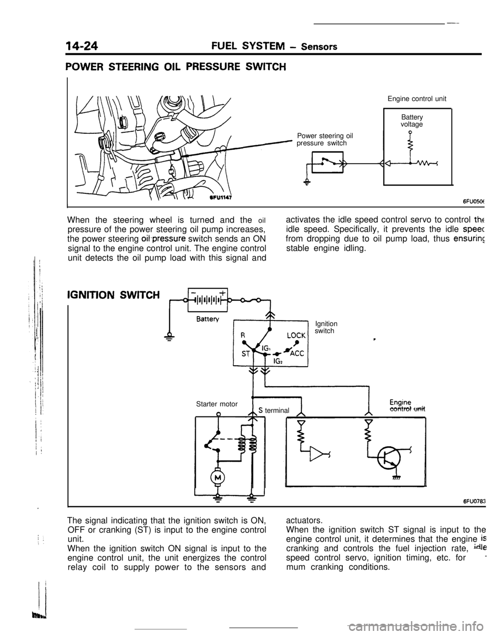
POWER STEERING OIL PRESSURE SWITCHEngine control unit
Power steering oil
pressure switchBattery
voltage
6FUO5OtIWhen the steering wheel is turned and the oil
pressure of the power steering oil pump increases,
the power steering oifpressure switch sends an ON
signal to the engine control unit. The engine control
unit detects the oil pump load with this signal andactivates the idle speed control servo to control
theidle speed. Specifically, it prevents the idle
speecfrom dropping due to oil pump load, thus
ensuringstable engine idling.IGNITION
SWITCH
1IBattery
Ignition
switch
Starter motor
aS terminalcontrol unit
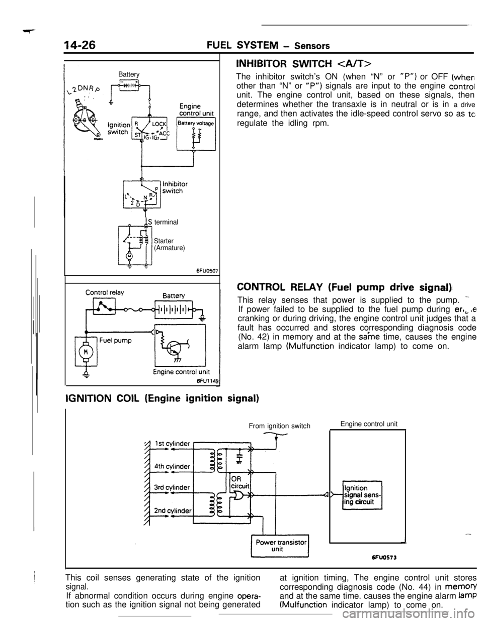
6FUO762The signal indicating that the ignition switch is ON,
OFF or cranking (ST) is input to the engine control
unit.
When the ignition switch ON signal is input to the
engine control unit, the unit energizes the control
relay coil to supply power to the sensors and
actuators.When the ignition switch ST signal is input to the
engine control unit, it determines that the engine
iscranking and controls the fuel injection rate,
despeed control servo, ignition timing, etc. for
-mum cranking conditions.
Page 138 of 391
Page 142 of 391
14-30SELF-DIAGNOSISFUEL SYSTEM- Engine Control Unit
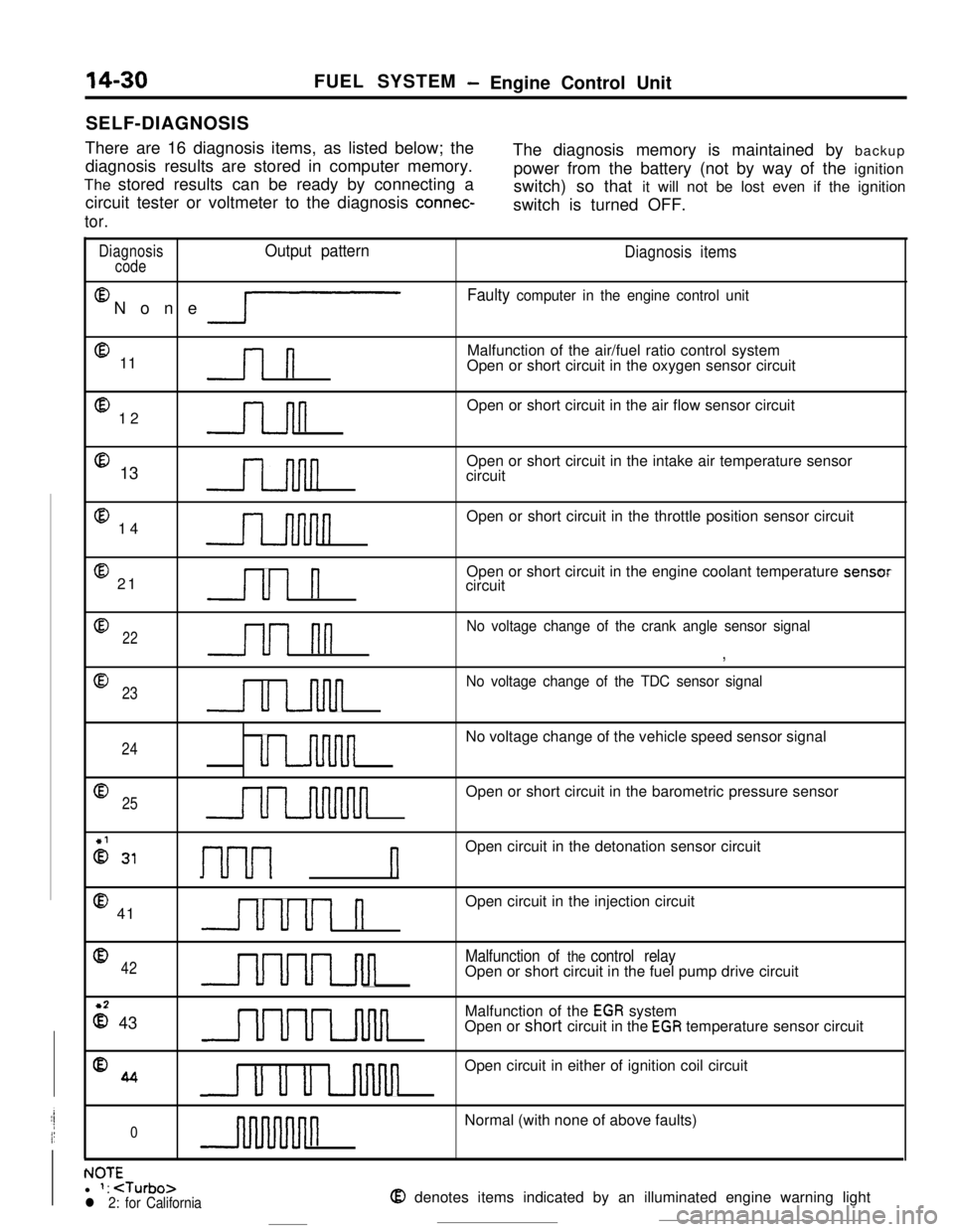
There are 16 diagnosis items, as listed below; the
diagnosis results are stored in computer memory.The diagnosis memory is maintained by backup
The stored results can be ready by connecting apower from the battery (not by way of the ignition
circuit tester or voltmeter to the diagnosis
connec-switch) so that it will not be lost even if the ignition
switch is turned OFF.
tor.
DiagnosisOutput pattern
codeEl
None
lP
@ 11l-l
@ 12n@ 13
@ 14
@ 21Ul n
Diagnosis items
Faulty computer in the engine control unitMalfunction of the air/fuel ratio control system
Open or short circuit in the oxygen sensor circuit
Open or short circuit in the air flow sensor circuit
Open or short circuit in the intake air temperature sensor
circuit
Open or short circuit in the throttle position sensor circuit
Open or short circuit in the engine coolant temperature sensor
circuit
022u1 nn
No voltage change of the crank angle sensor signal
,
@
23
u u-inn
No voltage change of the TDC sensor signal
24uu-uvinnnnNo voltage change of the vehicle speed sensor signal
Q25uuuuuunnnnnOpen or short circuit in the barometric pressure sensor
2 31I-~-~---~ nOpen circuit in the detonation sensor circuit
@ 41uuul nOpen circuit in the injection circuit
042UUuLJul
Malfunction of the control relayOpen or short circuit in the fuel pump drive circuit
z 43UUULnlulMalfunction of the
EGR system
Open or short circuit in the EGR temperature sensor circuit
%4u u u uvinnOpen circuit in either of ignition coil circuit
0nNormal (with none of above faults)
. IA-r-NUltl 1: