warning light MITSUBISHI ECLIPSE 1990 Service Manual
[x] Cancel search | Manufacturer: MITSUBISHI, Model Year: 1990, Model line: ECLIPSE, Model: MITSUBISHI ECLIPSE 1990Pages: 391, PDF Size: 15.27 MB
Page 55 of 391
ELECTRICAL - Fuses8-3q
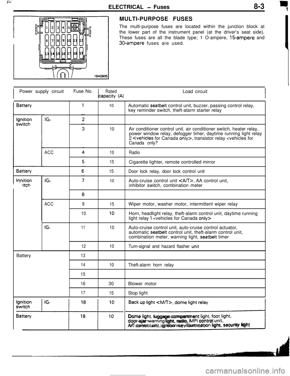
rMULTI-PURPOSE FUSES
The multi-purpose fuses are located within the junction block at
the lower part of the instrument panel (at the driver’s seat side).
These fuses are all the blade type; 1 O-ampere, 15-ampere and
30-ampere fuses are used.
IPower supply circuitFuse No.
RatedLoad circuitapacity
(A)IBattery
t-lonition,itchBattery
IGz
ACC
IG,
10
10
10
15
15
10Automatic seatbelt control unit, buzzer, passing control relay,
key reminder switch, theft-alarm starter relay
Air conditioner control unit, air conditioner switch, heater relay,
power window relay, defogger timer, daytime running light relay
2
Door lock relay, door lock control unitAuto-cruise control unit
, AA control unit,
inhibitor switch, combination meter
ACC
IGI9
1011
12
1315
10
10
10Wiper motor, washer motor, intermittent wiper relay
Horn, headlight relay, theft-alarm control unit, daytime running
light relay
1
automatic seatbelt control unit, theft-alarm control unit,
combination meter, warning light, seatbelt timer
Turn-signal and hazard flasher u.nit
14
15
16
17
10Theft-alarm horn relay
30Blower motor
15Stop light
Back up light
CM/T>, dome light relay
!Dome light. luggage compartment
Irght, foot. Irght.door-ajar warntng light, radio, MPI control unrt.AK control unit, ignition key illumination light.security lightI
Page 56 of 391
_--
8-4ELECTRICAL - Fuses / Diagnosis System
61543
2
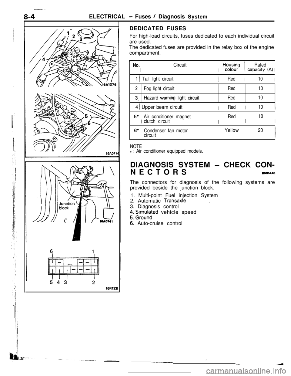
16R133lDEDICATED FUSES
For high-load circuits, fuses dedicated to each individual circuit
are used.
The dedicated fuses are provided in the relay box of the engine
compartment.
No.
I
Circuit
I
H,“d;;-;I
Rated
canacitv (A)I
1 1 Tail light circuitIRedI10I
2Fog light circuitRed10
3,.Hazard warning light circuitRed10
4 ) Upper beam circuitIRedI10I
5’
I
Air conditioner magnet
I
Red
I
10
clutch circuitI
6’Condenser fan motorYellow20
circuitI
NOTEl : Air conditioner equipped models.DIAGNOSIS SYSTEM
- CHECK CON-
NECTORS
nmcwaBThe connectors for diagnosis of the following systems are
provided beside the junction block.
1. Multi-point Fuel injection System
2. Automatic
Transaxle.3. Diagnosis control
z. grm.rlnaFd vehicle speed
6: Auto-cruise control
:..--.-__-.
Page 84 of 391
8-32ELECTRICAL - Theft-alarm System
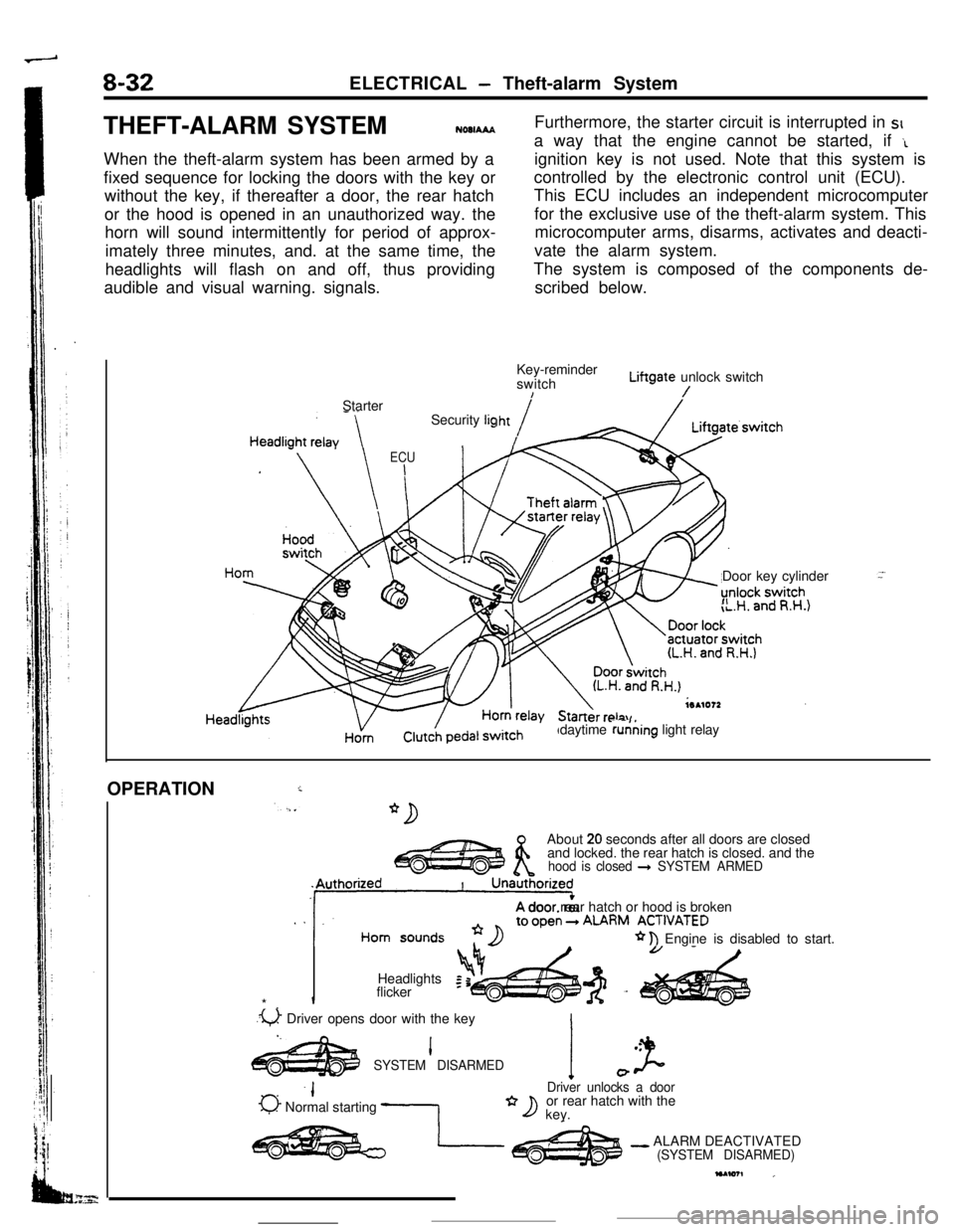
THEFT-ALARM SYSTEM
NOOIAAAWhen the theft-alarm system has been armed by a
fixed sequence for locking the doors with the key or
without the key, if thereafter a door, the rear hatch
or the hood is opened in an unauthorized way. the
horn will sound intermittently for period of approx-
imately three minutes, and. at the same time, the
headlights will flash on and off, thus providing
audible and visual warning. signals.Furthermore, the starter circuit is interrupted in SIa way that the engine cannot be started, if
‘Lignition key is not used. Note that this system is
controlled by the electronic control unit (ECU).
This ECU includes an independent microcomputer
for the exclusive use of the theft-alarm system. This
microcomputer arms, disarms, activates and deacti-
vate the alarm system.
The system is composed of the components de-
scribed below.
Key-reminder
switchLiftgate unlock switch
!/Starter
Door key cylinder
”daytime running light relay Security
lig
ECU
I
HornOPERATION
iAbout
20 seconds after all doors are closed
and locked. the rear hatch is closed. and the
hood is closed + SYSTEM ARMED
. .‘11A door rear hatch or hood is brokenALARM ACT,“ATED
* n Engine is disabled to start.
Headlights
Iflicker
*.
.u Driver opens door with the key
I.l .
SYSTEM DISARMEDI J-0
-IDriver unlocks a door
0 Normal starting -1or rear hatch with the*D key.
- ALARM DEACTIVATED(SYSTEM DISARMED)
Page 119 of 391
FUEL SYSTEM -Fuel Supply and Fuel Pressure Control14-7FUEL TANK
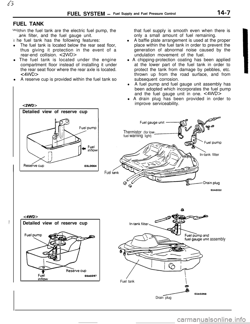
m/ithin the fuel tank are the electric fuel pump, the
.ank filter, and the fuel gauge unit.
-I he fuel tank has the following features:
lThe fuel tank is located below the rear seat floor,thus giving it protection in the event of a
rear-end collision.
<2WD>l The fuel tank is located under the engine
compartment floor instead of installing it under
the rear seat floor where the rear axle is located.
<4WD>lA reserve cup is provided within the fuel tank so
!Detailed view of reserve cup
t2WD>Detaiied view of reserve cup
t4WD>
Fuel03AO267
Fuelthat fuel supply is smooth even when there is
only a small amount of fuel remaining.
lA baffle plate arrangement is used at the proper
place within the fuel tank in order to prevent the
generation of abnormal noise caused by the
undulation movement of the fuel.
l A chipping-protection coating has been applied
at the lower part of the fuel tank in order to
protect the tank from damage by pebbles, etc.
thrown up from the road surface, and from
subsequent corrosion.
lA fuel pump and fuel gauge unit assembly has
been adopted which incorporates the fuel pump
and the fuel gauge unit in one.
<4WD>l A drain plug has been provided in order to
improve serviceability.
Thermistor (for low
fuel warning light)In-tank filter
Fuel tankI
e
/ 03AO268
Drain plug
assembly
Page 140 of 391

---_-
14-28FUEL SYSTEM- Ennine Control Unit
The engine control unit has an
onboard diagnosis
function, which is used mainly to diagnose the
sensors, thus facilitating system checks and troub-leshooting. It also has a fail-safe/backup function tc
ensure passenger and vehicle safety.
Onboard self-
diagnosisMainly for detecting failure of sensors
and foroutputting diagnosis code.
for detecting failure of sensors, etc. related
toemission control and to turn ON warning light
(Malfunction indicator light).
> Codes can be read by voltmeter.
ENGINE CHECK light is turned
2 ON.
The engine control unit is mounted in the passenger compart-
ment, at the location indicated in the illustration.,
Page 141 of 391
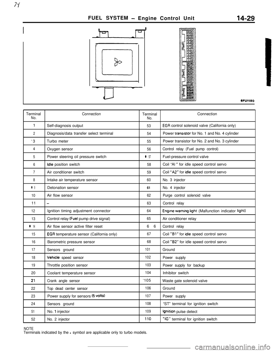
FUEL SYSTEM- Engine Control Unit14-29
SFUllSOTerminal
ConnectionTerminalConnectionNo.
No.
1Self-diagnosis output53EGR control solenoid valve (California only)
2Diagnosis/data transfer select terminal54Power transrstor for No. 1 and No. 4 cylinder
‘3Turbo meter
55Power transistor for No. 2 and No. 3 cylinder
4Oxygen sensor56Control relay (Fuel pump control)
5Power steering oil pressure switchl 57Fuel-pressure control valve
6Idle position switch58Coil “Al ” for idle speed control servo
7Air conditioner switch59Coil “A2” for idle speed control servo
8Intake air temperature sensor60No. 3 injector
l 9Detonation sensor61No. 4 injector
10Air flow sensor62Purge control solenoid valve11
-63Control relay
12Ignition timing adjustment connector64Engine warning irght (Malfunction indicator light)
13Control relay (Fuel pump drive signal)65Air conditioner relay
l 14Air flow sensor active filter reset66Control relay
15EGR temperature sensor (California only)67Coil “Bl ” for idle speed control servo
16Barometric pressure sensor68Coil “B2” for idle speed control servo
17Sensors ground101Ground
18Vehicle speed sensor102Power supply
19Throttle position sensor103Power supply for backup
20Coolant temperature sensor
104Inhibitor switch
21Crank angle sensor‘105
Waste gate solenoid valve
22Top dead center sensor106Ground
23Power supply for sensors (5 volts)107Power supply
24Sensors ground108“ST” terminal for ignition switch
51No. 1 injector109Ignition pulse detect
52No. 2 injector170“IG ” terminal for ignition switch
NOTETerminals indicated by the l symbol are applicable only to turbo models.
Page 142 of 391
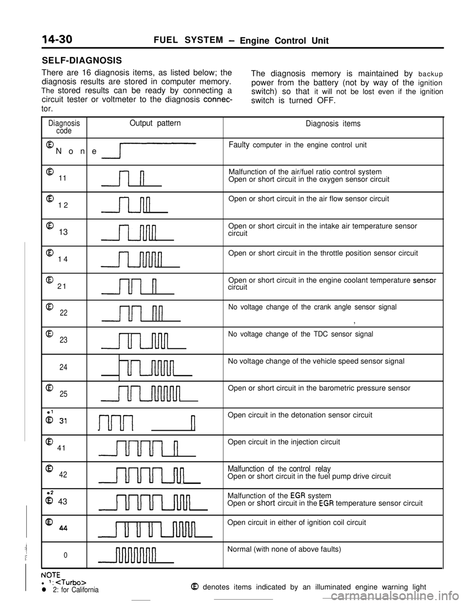
14-30SELF-DIAGNOSISFUEL SYSTEM- Engine Control Unit
There are 16 diagnosis items, as listed below; the
diagnosis results are stored in computer memory.The diagnosis memory is maintained by backup
The stored results can be ready by connecting apower from the battery (not by way of the ignition
circuit tester or voltmeter to the diagnosis
connec-switch) so that it will not be lost even if the ignition
switch is turned OFF.
tor.
DiagnosisOutput pattern
codeEl
None
lP
@ 11l-l
@ 12n@ 13
@ 14
@ 21Ul n
Diagnosis items
Faulty computer in the engine control unitMalfunction of the air/fuel ratio control system
Open or short circuit in the oxygen sensor circuit
Open or short circuit in the air flow sensor circuit
Open or short circuit in the intake air temperature sensor
circuit
Open or short circuit in the throttle position sensor circuit
Open or short circuit in the engine coolant temperature sensor
circuit
022u1 nn
No voltage change of the crank angle sensor signal
,
@
23
u u-inn
No voltage change of the TDC sensor signal
24uu-uvinnnnNo voltage change of the vehicle speed sensor signal
Q25uuuuuunnnnnOpen or short circuit in the barometric pressure sensor
2 31I-~-~---~ nOpen circuit in the detonation sensor circuit
@ 41uuul nOpen circuit in the injection circuit
042UUuLJul
Malfunction of the control relayOpen or short circuit in the fuel pump drive circuit
z 43UUULnlulMalfunction of the
EGR system
Open or short circuit in the EGR temperature sensor circuit
%4u u u uvinnOpen circuit in either of ignition coil circuit
0nNormal (with none of above faults)
. IA-r-NUltl 1:
Page 143 of 391
FUEL SYSTEM - Engine Control Unit14-31
r
L
IMPI
Ground
1 Engine control unit
Engine wam-
$b?Stionindicator
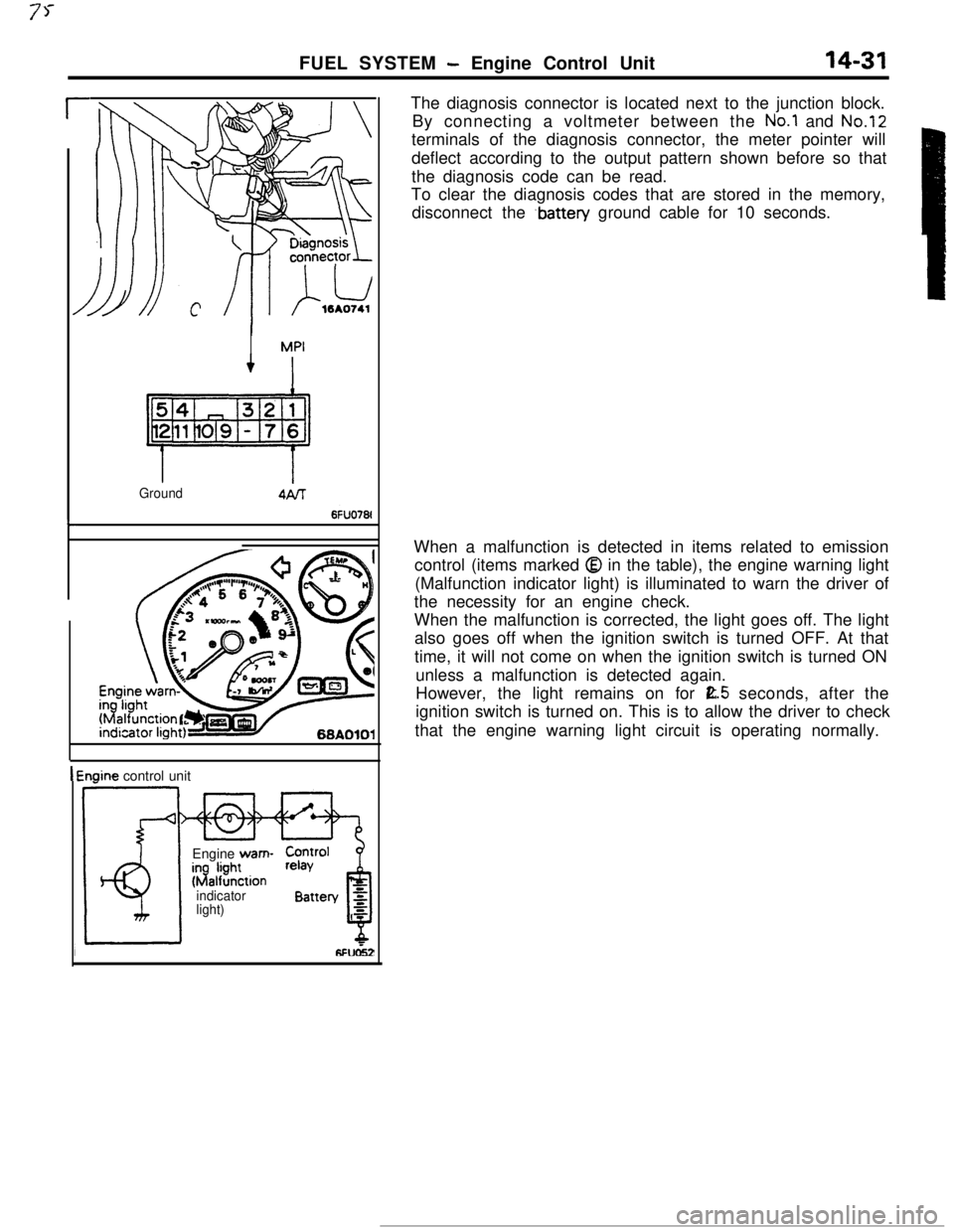
light)The diagnosis connector is located next to the junction block.
By connecting a voltmeter between the
No.1 and No.12terminals of the diagnosis connector, the meter pointer will
deflect according to the output pattern shown before so that
the diagnosis code can be read.
To clear the diagnosis codes that are stored in the memory,
disconnect the
.battery ground cable for 10 seconds.
When a malfunction is detected in items related to emission
control (items marked
Q in the table), the engine warning light
(Malfunction indicator light) is illuminated to warn the driver of
the necessity for an engine check.
When the malfunction is corrected, the light goes off. The light
also goes off when the ignition switch is turned OFF. At that
time, it will not come on when the ignition switch is turned ON
unless a malfunction is detected again.
However, the light remains on for
E.5 seconds, after the
ignition switch is turned on. This is to allow the driver to check
that the engine warning light circuit is operating normally.
Page 350 of 391
BODY - Seat Belts23-33
Gear eGear B
Energy-absorbingbelt
Before absorbing
shock
19AO332Inward
Forward
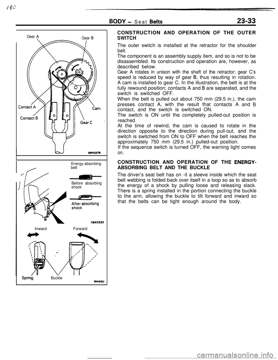
Sprin$BuckleCONSTRUCTION AND OPERATION OF THE OUTER
SWITCHThe outer switch is installed at the retractor for the shoulder
belt.The component is an assembly supply item, and so is not to be
disassembled. Its construction and operation are, however, as
described below.
Gear A rotates in unison with the shaft of the retractor; gear C’sspeed is reduced by way of gear
B, thus resulting in rotation.
A cam is installed to gear C. In the illustration, the belt is at the
fully rewound position; contacts A and
B are separated, and the
switch is switched OFF.
When the belt is pulled out about 750 mm (29.5 in.), the cam
presses contact A, with the result that contacts A and
Bcontact, and the switch is switched ON.
The switch is ON until the completely pulled-out position is
reached.At the time of rewind, the cam is caused to rotate in the
direction opposite to the direction during pull-out, and the
switch is switched from ON to OFF when the belt reaches the
approximately 750 mm (29.5 in.) pulled-out position.
If the sequence switch is turned OFF, the warning light comes
on.CONSTRUCTION AND OPERATION OF THE
ENERGY-ABSORBING BELT AND THE BUCKLE
The driver’s seat belt has on -it a sleeve inside which the seat
belt webbing is folded back over itself in a loop so as to absorb
the energy of a shock by pulling loose and releasing slack.
There is a spring installed in the portion connecting the buckle
to the arm, allowing the buckle to tilt forward and inward so
that the belts can be tight enough around the body.
Page 354 of 391
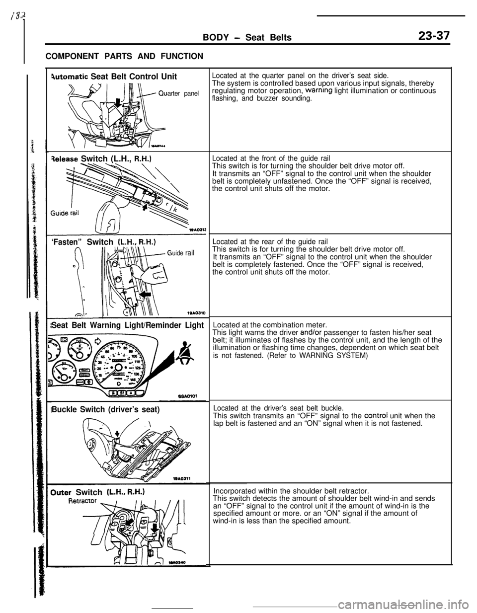
BODY - Seat Belts23-37COMPONENT PARTS AND FUNCTION
4utomatic Seat Belt Control Unit
arter panel
qelease Switch (L.H., R.H.)
‘Fasten”Switch (L.H., R.H.)
uide rail
1SAO310
Seat Belt Warning Light/Reminder Light
Buckle Switch (driver’s seat)
Outer Switch (LH., R.H.)
Located at the quarter panel on the driver’s seat side.The system is controlled based upon various input signals, thereby
regulating motor operation,
warnrng light illumination or continuousflashing, and buzzer sounding.
Located at the front of the guide railThis switch is for turning the shoulder belt drive motor off.
It transmits an “OFF” signal to the control unit when the shoulder
belt is completely unfastened. Once the “OFF” signal is received,
the control unit shuts off the motor.
Located at the rear of the guide railThis switch is for turning the shoulder belt drive motor off.
It transmits an “OFF” signal to the control unit when the shoulder
belt is completely fastened. Once the “OFF” signal is received,
the control unit shuts off the motor.
Located at the combination meter.
This light warns the driver
and/or passenger to fasten his/her seat
belt; it illuminates of flashes by the control unit, and the length of the
illumination or flashing time changes, dependent on which seat belt
is not fastened. (Refer to WARNING SYSTEM)
Located at the driver’s seat belt buckle.This switch transmits an “OFF” signal to the
control unit when the
lap belt is fastened and an “ON” signal when it is not fastened.
Incorporated within the shoulder belt retractor.
This switch detects the amount of shoulder belt wind-in and sends
an “OFF” signal to the control unit if the amount of wind-in is the
specified amount or more. or an “ON” signal if the amount of
wind-in is less than the specified amount.