brake light MITSUBISHI ECLIPSE 1990 Service Manual
[x] Cancel search | Manufacturer: MITSUBISHI, Model Year: 1990, Model line: ECLIPSE, Model: MITSUBISHI ECLIPSE 1990Pages: 391, PDF Size: 15.27 MB
Page 8 of 391
o-4GENERAL - Technical Features
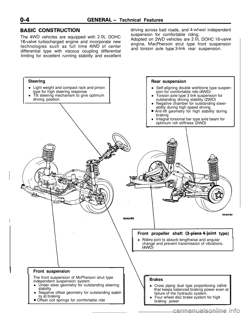
BASIC CONSTRUCTION
The 4WD vehicles are equipped with
2.OL DOHC
16-valve turbocharged engine and incorporate new
technologies such as full time 4WD of center
differential type with viscous coupling differential
limiting for excellent running stability and excellent
Steering
l Light weight and compact rack and pinion
type for high steering response
l Tilt steering mechanism to give optimum
driving position
\driving across bad roads, and $-wheel independent
suspension for comfortable riding.
Adopted on
2WD vehicles are 2.OL DOHC 16-valveengine, MacPherson strut type front suspension
and torsion axle
typ.e 3-link rear suspension.
Rear suspension
l Self-aligning double wishbone type suspen-
sion for comfortable ride
(4WD)l Torsion axle type 3 link suspension for
outstanding driving stability
(2WD)l Negative chamber for outstanding steer-
ability during high speed driving
0 Anti-lift geometry for high stability duringbraking
lIntegral torsional bar type axle beam for
optimum roll stiffness (2WD)
\Front propeller shaft (3-piece
4-joint type)
lRobro joint to absorb lengthwise and angular
change and prevent transmission of vibrations.
(4WD)
IFront suspension
The front suspension of McPherson strut type
independent suspension system
l Under steer geometry for outstanding steering
stability
l Negative offset geometry for outstanding
stabil-ity at braking
0 Offset coil springs for comfortable ride
Brakes
l Cross piping dual type proportioning valvethat keeps balanced braking power even at
failure of the hydraulic system.
l Four wheel disc brake system for high
braking power.
Page 176 of 391
![MITSUBISHI ECLIPSE 1990 Service Manual 14-64FUEL SYSTEM - Auto-cruise Control System
FixedAccelera-FixedSpeed -c tion-LC speed
High
Vehic’e iapprox. 40 km/hspeedG!5 mph) or hagher]Low
’When the RESUME
(ACCEL) Switch is Kept Turned
Whi MITSUBISHI ECLIPSE 1990 Service Manual 14-64FUEL SYSTEM - Auto-cruise Control System
FixedAccelera-FixedSpeed -c tion-LC speed
High
Vehic’e iapprox. 40 km/hspeedG!5 mph) or hagher]Low
’When the RESUME
(ACCEL) Switch is Kept Turned
Whi](/img/19/57103/w960_57103-175.png)
14-64FUEL SYSTEM - Auto-cruise Control System
FixedAccelera-FixedSpeed -c tion-LC speed
High
Vehic’e iapprox. 40 km/hspeedG!5 mph) or hagher]Low
’When the RESUME
(ACCEL) Switch is Kept Turned
While the RESUME switch is ON, the actuator’s DC
mote,caused to rotate to the PULL side; the vehicle speed when the
switch is switched OFF as acceleration continues is entered in
the memory, and is thereafter controlled as the fixed speed.
CANCELLATION
When, during fixed-speed driving, the signals described below
are input, conductivity to the electromagnetic clutch is inter-
rupted, thus
cancelling the auto-cruise control system.
l Stop light switch ON (brake pedal depressed)
l Clutch switch ON (clutch pedal depressed)
lInhibitor switch ON (selector lever at
“P” or “N” position)
LOW-SPEED LIMIT
There is automatic cancellation at or below the low-speed limit
vehicle speed [approximately 40 km/h (25 mph)].
HIGH-SPEED LIMIT
The vehicle cannot be driven at a fixed speed which is at or
higher than the high-speed limit [approximately 145 km/h
(90
mph)l.Note that the vehicle speed memorized when the SET switch
a5pressed while the vehicle is traveling at the high-speed limit or
higher
vvill be the high-speed limit vehicle speed.
FAIL-SAFE FUNCTION
When the following situations are encountered during fixed-
speed driving, the signals to interrupt, conductivity to the
electromagnetic clutch are input, thus canceling the auto-cruise
control system.
0
0
0When vehicle speed decreases to the low-speed limit
[approx. 40 km/h (25 mph)].
If the vehicle speed decreases to a speed which is
approximately 20 km/h (12 mph) or more below ‘the
memorized vehicle speed.
When the vehicle speed drops by 20 km/h
(12 mph) or more
after having reached the set speed -10 km/h (-6 mph) in
the RESUME mode.
If there is damaged or disconnected wiring of the input line
(stop light switch load side) of the stop light switch.
if there is no input of the vehicle speed signal for a certain
fixed time (1 second or longer).
If the SET and RESUME control switches are switched ON
at the same time.
If the cancel switches (stop light switch, clutch switch or
inhibitor switch) and command switches (SET switch
orRESUME switch) are switched ON at the same time.
if the actuator clutch driver (transistor) of the control unk
remains ON (short-circuit).
Page 182 of 391
14-70
-_FUEL SYSTEM
- Auto-cruise Control System
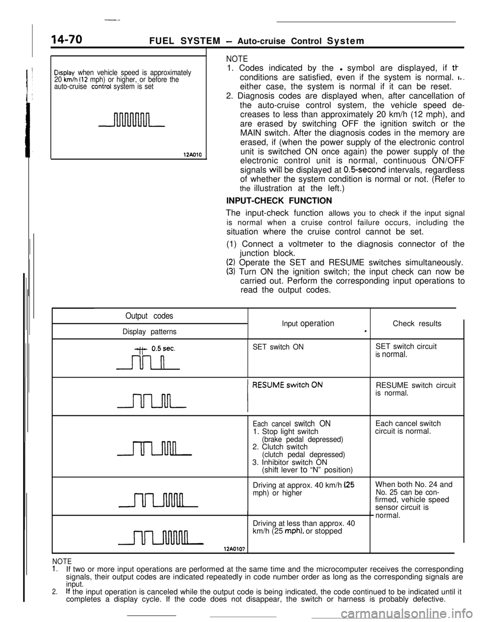
Display when vehicle speed is approximately
20 km/h (12 mph) or higher, or before the
auto-cruise conrrol system is set
12AolO
NOTE1. Codes indicated by thel symbol are displayed, if
tt-conditions are satisfied, even if the system is normal.
I,.either case, the system is normal if it can be reset.
2. Diagnosis codes are displayed when, after cancellation of
the auto-cruise control system, the vehicle speed de-
creases to less than approximately 20 km/h (12 mph), and
are erased by switching OFF the ignition switch or the
MAIN switch. After the diagnosis codes in the memory are
erased, if (when the power supply of the electronic control
unit is switched ON once again) the power supply of the
electronic control unit is normal, continuous ON/OFF
signals will be displayed at
O.&second intervals, regardless
of whether the system condition is normal or not. (Refer to
the illustration at the left.)
INPUT-CHECK FUNCTION
The input-check function allows you to check if the input signal
is normal when a cruise control failure occurs, including the
situation where the cruise control cannot be set.
(1) Connect a voltmeter to the diagnosis connector of the
junction block.
(2) Operate the SET and RESUME switches simultaneously.
(3) Turn ON the ignition switch; the input check can now be
carried out. Perform the corresponding input operations to
read the output codes.
Output codes
Display patternsInput
operationCheck resultst
y- 0.5sec.
n
SET switch ONSET switch circuitis normal.RESUME switch circuit
is normal.
Each cancel switch ON1. Stop light switch
(brake pedal depressed)2. Clutch switch
(clutch pedal depressed)3. Inhibitor switch ON
(shift lever to “N” position)Each cancel switch
circuit is normal.
Driving at approx. 40 km/h
(25mph) or higherWhen both No. 24 andNo. 25 can be con-firmed, vehicle speed
sensor circuit is
normal.Driving at less than approx. 40
km/h (25
mph). or stopped
NOTE1.If two or more input operations are performed at the same time and the microcomputer receives the corresponding
signals, their output codes are indicated repeatedly in code number order as long as the corresponding signals are
2.input.If the input operation is canceled while the output code is being indicated, the code continued to be indicated until it
completes a display cycle. If the code does not disappear, the switch or harness is probably defective.
Page 186 of 391
14-74
_ ,.-..FUEL SYSTEM
- Auto-cruise Control System
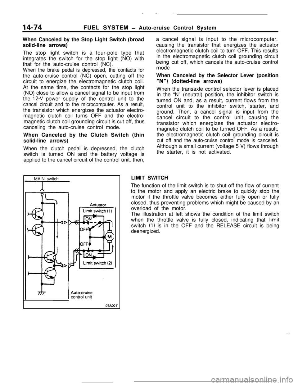
When Canceled by the Stop Light Switch (broad
solid-line arrows)
The stop light switch is a four-pole type that
integrates the switch for the stop light (NO) with
that for the auto-cruise control (NC).
When the brake pedal is depressed, the contacts forthe auto-cruise control (NC) open, cutting off the
circuit to energize the electromagnetic clutch coil.
At the same time, the contacts for the stop light
(NO) close to allow a cancel signal to be input from
the
12-V power supply of the control unit to the
cancel circuit and to the microcomputer. As a result,the transistor which energizes the actuator electro-
magnetic clutch coil turns OFF and the electro-
magnetic clutch coil grounding circuit is cut off, thus
canceling the auto-cruise control mode.
When Canceled by the Clutch Switch (thin
solid-line arrows)
When the clutch pedal is depressed, the clutch
switch is turned ON and the battery voltage is
applied to the cancel circuit of the control unit. then,a cancel signal is input to the microcomputer.
causing the transistor that energizes the actuator
electromagnetic clutch coil to turn OFF. This results
in the electromagnetic clutch coil grounding circuit
bma$ndge cut off, which cancels the auto-cruise control
When Canceled by the Selector Lever (position“N”) (dotted-line arrows)
When the transaxle control selector lever is placed
in the “N” (neutral) position, the inhibitor switch is
turned ON and, as a result, current flows from the
control unit to the inhibitor switch, starter, and
ground. Then, a cancel signal is input from the
cancel circuit to the control unit, causing the
transistor which energizes the actuator electro-
magnetic clutch coil to be turned OFF. As a result,
the electromagnetic clutch coil grounding circuit is
cut off and the auto-cruise control mode is canceled.Although a small current (voltage 5 V) flows through
the starter, it is not activated.
MAIN switchLIMIT SWITCH
The function of the limit switch is to shut off the flow of current
to the motor and apply an electric brake to quickly stop the
motor if the throttle valve becomes either fully open or fully
closed, thus preventing problems which might be caused by an
overload of the motor.
The illustration at left shows the condition of the limit switch
when the throttle valve is fully closed, indicating that
.limitswitch
(1) is in the OFF and the RELEASE circuit is being
deenergized.
IAutocruisecontrol unit
07Aool'
.-
Page 189 of 391
-- --.-*-.e *._,_-.&” :,.>~‘c,-.y~~ 7, . . --
FUEL SYSTEM- Auto-cruise Control System14-77
(For stop light)
OFF +-ON
0N -+-OFF
(For auto-cruise control)
16RO99r4 3
12
NCNO-w-w
I/0l-COFFOFF*~ON4
321NO: Normally opened
NC: Normally closed
07AOOl:
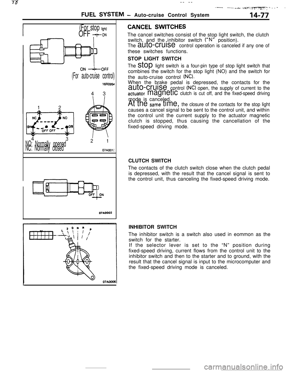
CANCEL SWITCHESThe cancel switches consist of the stop light switch, the clutch
switch, and the inhibitor switch
(“N” position).
The auto-cruise control operation is canceled if any one ofthese switches functions.
STOP LIGHT SWITCH
The stop light switch is a four-pin type of stop light switch thatcombines the switch for the stop light (NO) and the switch for
the auto-cruise control
(NC).When the brake pedal is depressed, the contacts for the
auto-cruise control (NC) open, the supply of current to the
actuator magnetic clutch is cut off, and the fixed-speed drivingmode is canceled.
At the Same time, the closure of the contacts for the stop lightcauses a cancel signal to be sent to the control unit, and within
the control unit the current supply to the actuator magnetic
clutch is stopped, thus causing the cancellation of the
fixed-speed driving mode.
CLUTCH SWITCH
The contacts of the clutch switch close when the clutch pedal
is depressed, with the result that the cancel signal is sent to
the control unit, thus canceling the fixed-speed driving mode.
INHIBITOR SWITCH
The inhibitor switch is a switch also used in eommon as the
switch for the starter.
If the selector lever is set to the “N” position during
fixed-speed driving, current flows from the control unit to the
inhibitor switch and then to the starter and to ground, with the
result that the cancel signal is input to the microcomputer and
the fixed-speed driving mode is canceled.
Page 273 of 391
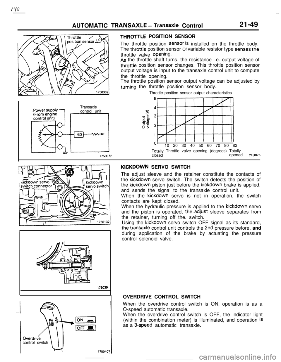
.-AUTOMATIC TRANSAXLE
- Transaxle Control21-49
Transaxlecontrol unit
Eel
6017!au72
THROmE POSITION SENSOR
The throttle position
SenSOr is installed on the throttle body.
The throttle position sensor Of variable resistor type
senses thethrottle valve
opening.
As the throttle shaft turns, the resistance i.e. output voltage of
throttle position sensor changes. This throttle position sensor
output voltage is input to the transaxle control unit to compute
the throttle opening.
The throttle position sensor output voltage can be adjusted by
turning the throttle position sensor body.
Throttle position sensor output characteristics
5
1
0’ ’10 20 30 40 50 60 70 80 82Totally Throttle valve opening (degrees) Totally
closedopened7FUO75control switchKICKDOWN SERVO SWITCH
The adjust sleeve and the retainer constitute the contacts of
the kickdown servo switch. The switch detects the position of
the kickdown piston just before the kickdown brake is applied,
and sends the signal to the transaxle control unit.
When the kickdown servo is not in operation, the switch
contacts are kept closed.
When the hydraulic pressure is applied to the kickdown servo
and the piston is operated,
the’adjust sleeve separates from
the retainer, turning off the. switch.
Using the kickdown servo switch OFF signal as its standard,
thetransaxle control unit controls the 2nd pressure before, and
during application of the brake by actuating the pressure
control solenoid valve.
OVERDRIVE CONTROL SWITCH
When the overdrive control switch is ON, operation is as a
O-speed automatic transaxle.
When the overdrive control switch is OFF, the indicator light
(within the combination meter) is illuminated, and operation
isas a
3-speed automatic transaxle.