weight MITSUBISHI ECLIPSE 1990 Service Manual
[x] Cancel search | Manufacturer: MITSUBISHI, Model Year: 1990, Model line: ECLIPSE, Model: MITSUBISHI ECLIPSE 1990Pages: 391, PDF Size: 15.27 MB
Page 8 of 391
o-4GENERAL - Technical Features
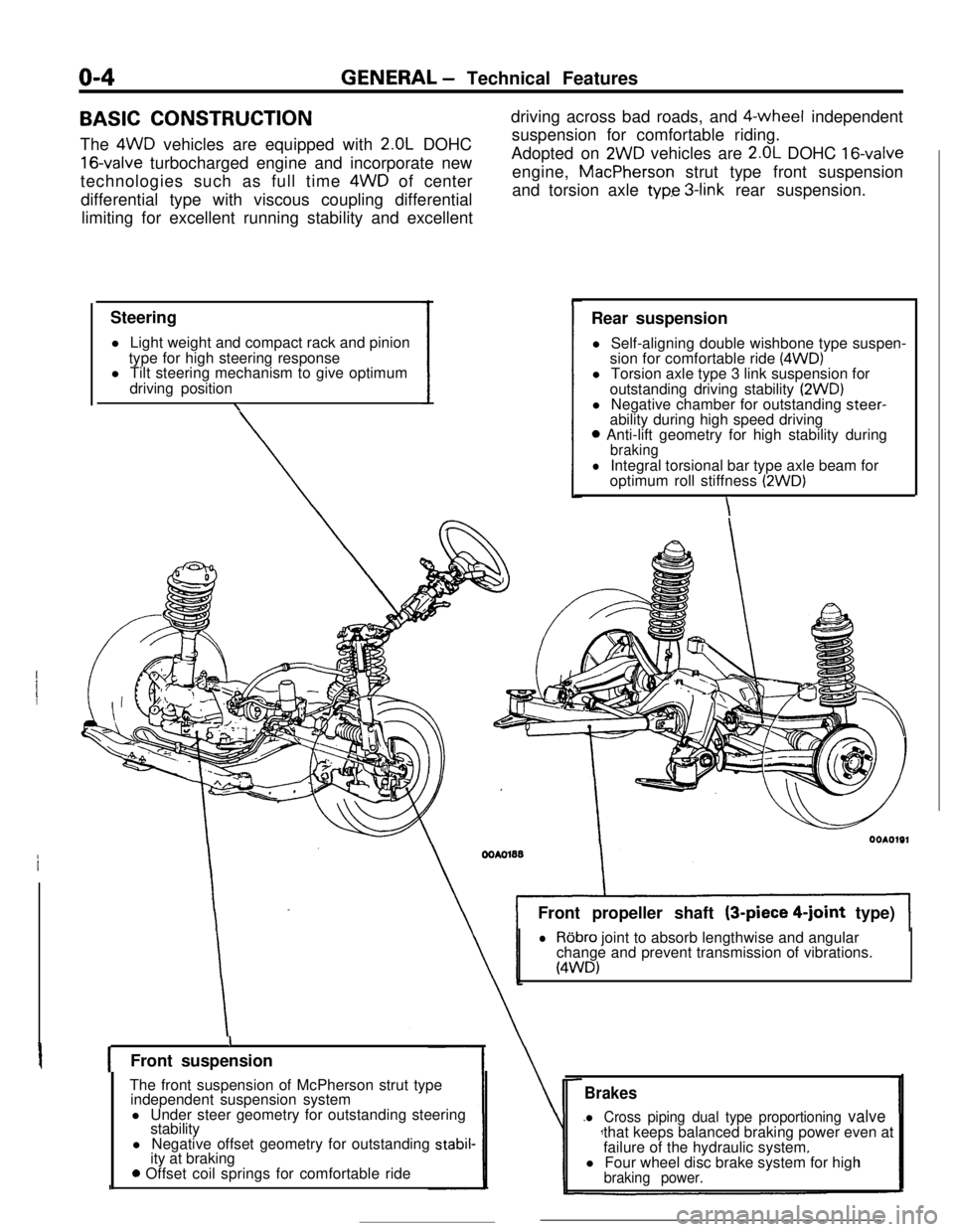
BASIC CONSTRUCTION
The 4WD vehicles are equipped with
2.OL DOHC
16-valve turbocharged engine and incorporate new
technologies such as full time 4WD of center
differential type with viscous coupling differential
limiting for excellent running stability and excellent
Steering
l Light weight and compact rack and pinion
type for high steering response
l Tilt steering mechanism to give optimum
driving position
\driving across bad roads, and $-wheel independent
suspension for comfortable riding.
Adopted on
2WD vehicles are 2.OL DOHC 16-valveengine, MacPherson strut type front suspension
and torsion axle
typ.e 3-link rear suspension.
Rear suspension
l Self-aligning double wishbone type suspen-
sion for comfortable ride
(4WD)l Torsion axle type 3 link suspension for
outstanding driving stability
(2WD)l Negative chamber for outstanding steer-
ability during high speed driving
0 Anti-lift geometry for high stability duringbraking
lIntegral torsional bar type axle beam for
optimum roll stiffness (2WD)
\Front propeller shaft (3-piece
4-joint type)
lRobro joint to absorb lengthwise and angular
change and prevent transmission of vibrations.
(4WD)
IFront suspension
The front suspension of McPherson strut type
independent suspension system
l Under steer geometry for outstanding steering
stability
l Negative offset geometry for outstanding
stabil-ity at braking
0 Offset coil springs for comfortable ride
Brakes
l Cross piping dual type proportioning valvethat keeps balanced braking power even at
failure of the hydraulic system.
l Four wheel disc brake system for high
braking power.
Page 16 of 391
o-12GENERAL - Vehicle Identification
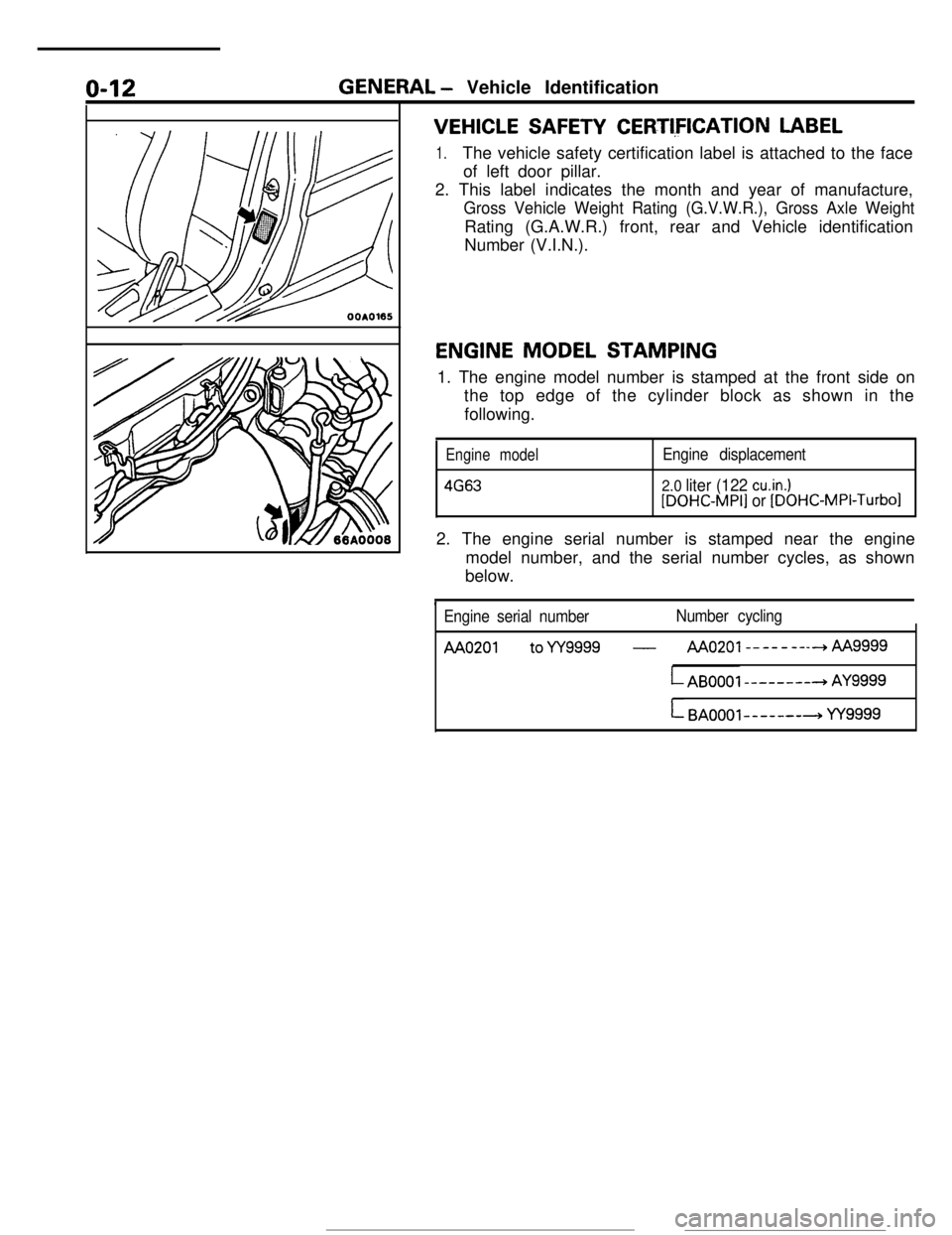
VEHICLE SAFETY CERTI,FICATION LABEL
1.The vehicle safety certification label is attached to the face
of left door pillar.
2. This label indicates the month and year of manufacture,
Gross Vehicle Weight Rating (G.V.W.R.), Gross Axle WeightRating (G.A.W.R.) front, rear and Vehicle identification
Number (V.I.N.).
ENGINE MODEL STAMPING
1. The engine model number is stamped at the front side on
the top edge of the cylinder block as shown in the
following.
Engine model
4663
Engine displacement
2.0 liter (122 cu.in.)[DOHC-MPI] or [DOHC-MPI-Turbo12. The engine serial number is stamped near the engine
model number, and the serial number cycles, as shown
below.
Engine serial numberNumber cycling
AA0201 toYY9999 -AAo201--------hAA
LAB0001 --------+ AY9999
L BAOOOl-------+ YY9999
Page 17 of 391
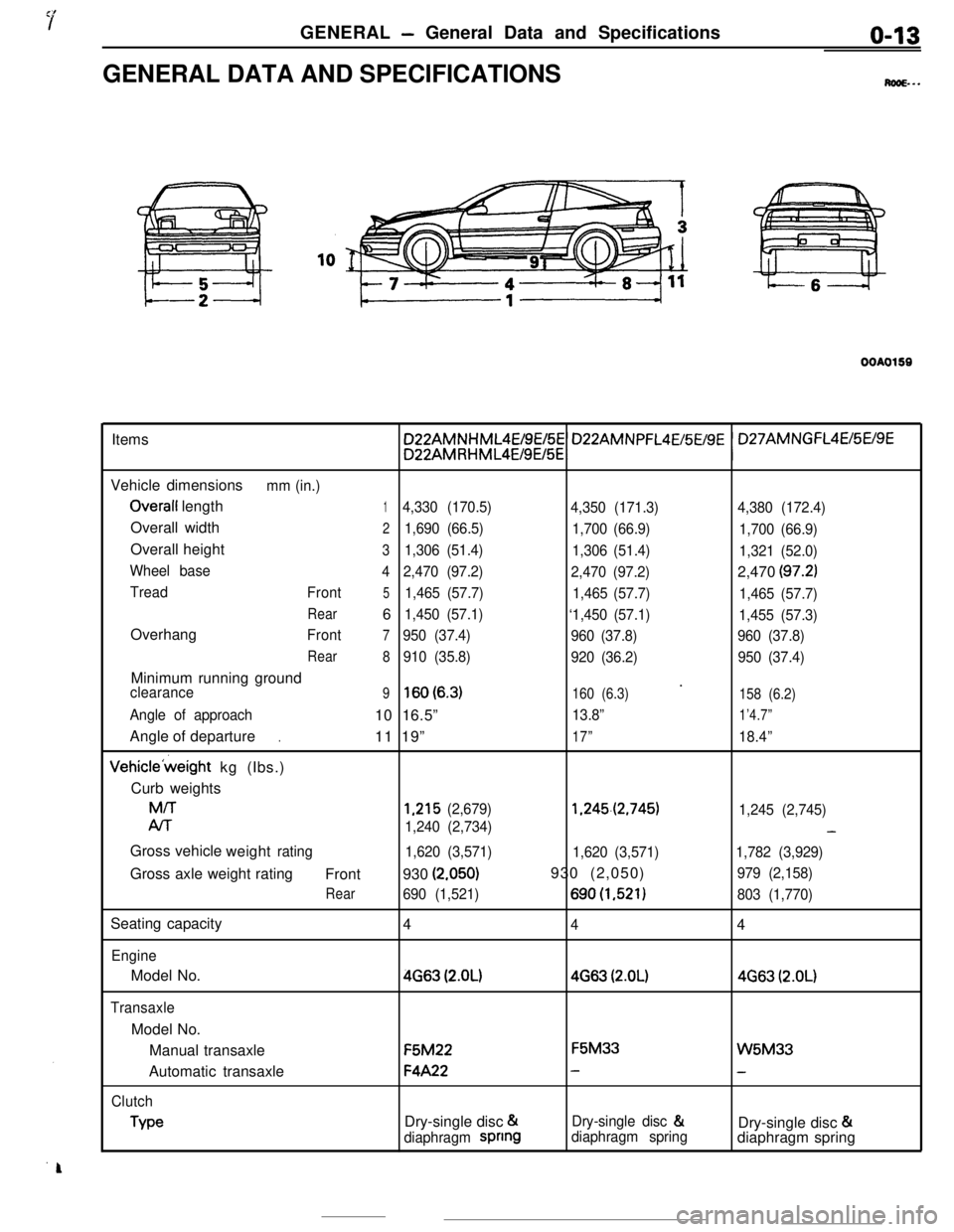
GENERAL - General Data and Specificationso-13GENERAL DATA AND SPECIFICATIONS
M...
OOAO159Items
Vehicle dimensions
mm (in.)
Overall length14,330 (170.5)
4,350 (171.3)4,380 (172.4)Overall width
21,690 (66.5)
1,700 (66.9)
1,700 (66.9)Overall height
31,306 (51.4)
1,306 (51.4)
1,321 (52.0)
Wheel base
42,470 (97.2)
2,470 (97.2)2,470
(97.2)
Tread
Front51,465 (57.7)
1,465 (57.7)
1,465 (57.7)
Rear61,450 (57.1)
‘1,450 (57.1)
1,455 (57.3)Overhang
Front7950 (37.4)
960 (37.8)960 (37.8)
Rear
8910 (35.8)
920 (36.2)950 (37.4)Minimum running ground
’clearance9lsO(6.3)160 (6.3)
158 (6.2)
Angle of approach10 16.5”13.8”1’4.7”Angle of departure
11 19”
17”18.4”.Vehicle’weight kg (Ibs.)
Curb weightsM/T
1,215 (2,679)1.245.(2,745)
1,245 (2,745)
Al-r
1,240 (2,734)-Gross vehicle
weight
rating
1,620 (3,571)
1,620 (3,571)1,782 (3,929)Gross axle weight rating
Front930
(2.050)930 (2,050)979 (2,158)
Rear690 (1,521)690(1,521)803 (1,770)Seating capacity
4
44
EngineModel No.
4663 (2.OL)4663 (2.OL)4663 (2.OL)
TransaxleModel No.
Manual transaxleF5M22F5M33
W5M33Automatic transaxle
F4A22--
Clutch
TypeDry-single disc &Dry-single disc &
Dry-single disc &
diaphragm spnngdiaphragm springdiaphragm spring
Page 20 of 391
2-2
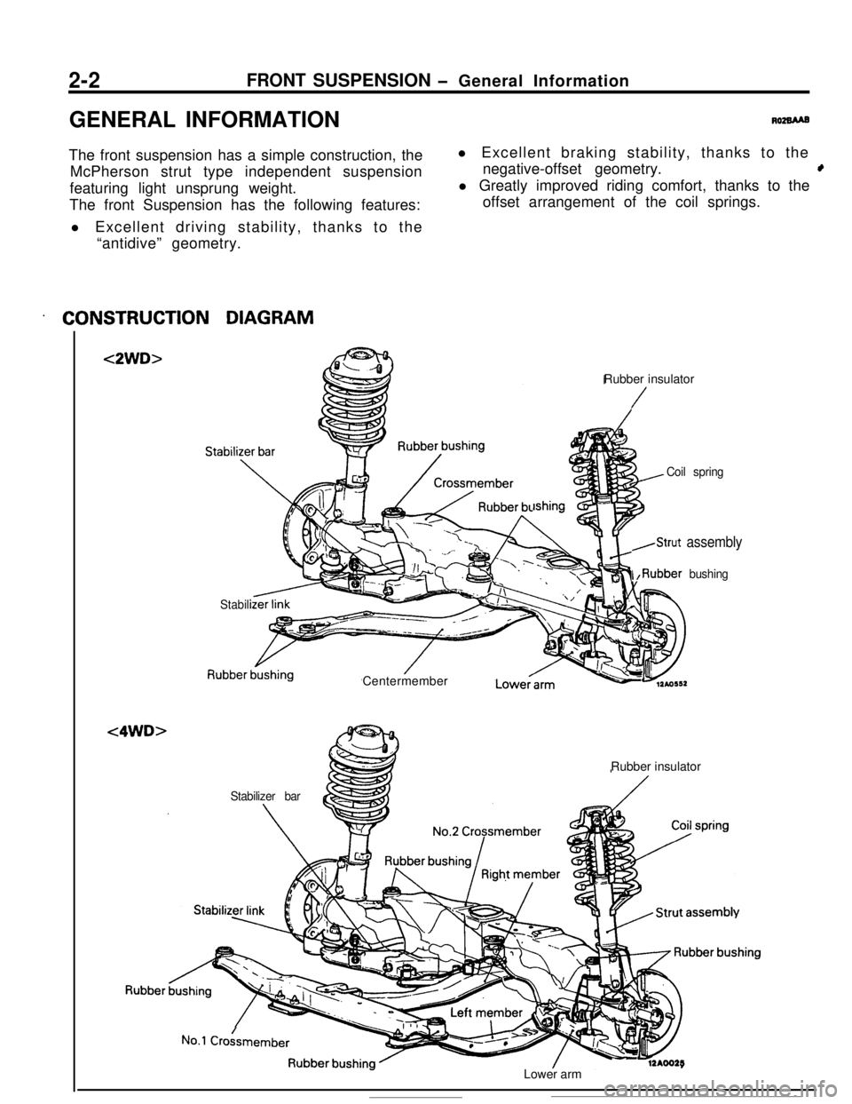
t
featuring light unsprung weight.
. CONSTRUCTION DIAGRAM
<2WD>
<4WD>
Rubber insulator
/
lshing
Coil spring
,Strut assembly
I ,Rubber bushing
Stabili
Lowecarm
Rubber insulator
No.1 Crokmember
- -12AOO25Lower arm
Page 152 of 391
14-40FUEL SYSTEM - Fuel Injection Control
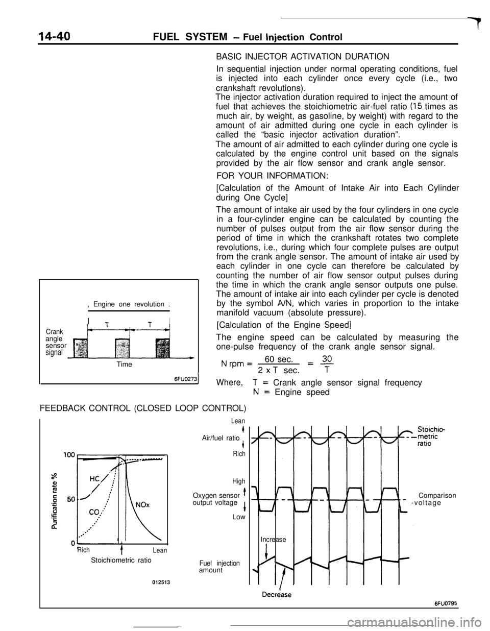
BASIC INJECTOR ACTIVATION DURATION
In sequential injection under normal operating conditions, fuel
is injected into each cylinder once every cycle (i.e., two
crankshaft revolutions).
The injector activation duration required to inject the amount of
fuel that achieves the stoichiometric air-fuel ratio
(15 times as
much air, by weight, as gasoline, by weight) with regard to the
amount of air admitted during one cycle in each cylinder is
called the “basic injector activation duration”.
The amount of air admitted to each cylinder during one cycle is
calculated by the engine control unit based on the signals
provided by the air flow sensor and crank angle sensor.
FOR YOUR INFORMATION:
Crankangle
sensor
signal, Engine one revolution .
I
TtI
t--“---t-+[Calculation of the Amount of Intake Air into Each Cylinder
during One Cycle]
The amount of intake air used by the four cylinders in one cycle
in a four-cylinder engine can be calculated by counting the
number of pulses output from the air flow sensor during the
period of time in which the crankshaft rotates two complete
revolutions, i.e., during which four complete pulses are output
from the crank angle sensor. The amount of intake air used by
each cylinder in one cycle can therefore be calculated by
counting the number of air flow sensor output pulses during
the time in which the crank angle sensor outputs one pulse.
The amount of intake air into each cylinder per cycle is denoted
by the symbol
A/N, which varies in proportion to the intake
manifold vacuum (absolute pressure).
[Calculation of the Engine
Speed]The engine speed can be calculated by measuring the
one-pulse frequency of the crank angle sensor signal.
Nrpm=60 sec.L!!L2
x T sec.TTime
6FUO27:31Where,FEEDBACK CONTROL (CLOSED LOOP CONTROL)
i
Rich1Lean
T= Crank angle sensor signal frequency
N= Engine speed
Lean
kAir/fuel ratiot
Rich
HighOxygen sensor
toutput voltage
1Low
Stoichiometric ratio
Fuel injectionamount
012513
I-
Lt
Comparison- -voltage
Increase
j/
Decriase
6FUO795
Page 163 of 391
FUEL SYSTEM -Idle Speed Control14-51
_ 0 (32)80 (175)Coolant temperature “C (“F)6FUO2653
ATarget position during operation
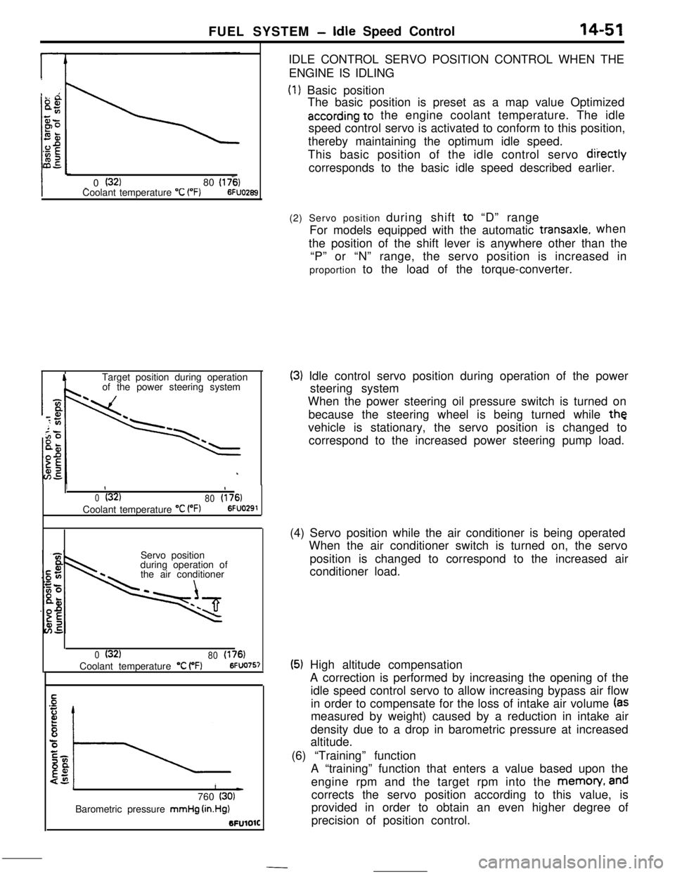
of the power steering systemIDLE CONTROL SERVO POSITION CONTROL WHEN THE
ENGINE IS IDLING
(1) Basic position
The basic position is preset as a map value Optimized
according to the engine coolant temperature. The idle
speed control servo is activated to conform to this position,
thereby maintaining the optimum idle speed.
This basic position of the idle control servo
diiectlycorresponds to the basic idle speed described earlier.
1II
0(32)
80(176)Coolant temperature
“C VW6FUO291Servo position
during operation of
the air conditioner
0(32)
80(176)Coolant temperature “C (“F)6FUO757
1L)760 (30)Barometric pressure mmHg
(in.Hg)BFUlOlC(2) Servo position during shift to “D” range
For models equipped with the automatic
transaxle.when
the position of the shift lever is anywhere other than the
“P” or “N” range, the servo position is increased in
proportion to the load of the torque-converter.
(3) Idle control servo position during operation of the power
steering system
When the power steering oil pressure switch is turned on
because the steering wheel is being turned while
thevehicle is stationary, the servo position is changed to
correspond to the increased power steering pump load.
(4) Servo position while the air conditioner is being operated
When the air conditioner switch is turned on, the servo
position is changed to correspond to the increased air
conditioner load.
(5) High altitude compensation
A correction is performed by increasing the opening of the
idle speed control servo to allow increasing bypass air flow
in order to compensate for the loss of intake air volume
(asmeasured by weight) caused by a reduction in intake air
density due to a drop in barometric pressure at increased
altitude.
(6) “Training” function
A “training” function that enters a value based upon the
engine rpm and the target rpm into the memon/,
andcorrects the servo position according to this value, is
provided in order to obtain an even higher degree of
precision of position control.
Page 211 of 391
19-2 POWER STEERING
Rlh
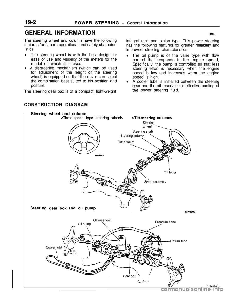
integral rack and pinion type. This power steering
oear and the oil reservoir for effective cooling of
Fhe power steering fluid.The steering gear box is of a compact, light-weight
Steering
SYJo& assembly
oil pump
\Pressure hose
A
Page 230 of 391
MANUAL TRANSAXLE <4WD> - General Information
MANUAL TRANSAXLE <4WD>
GENERAL INFORMATION
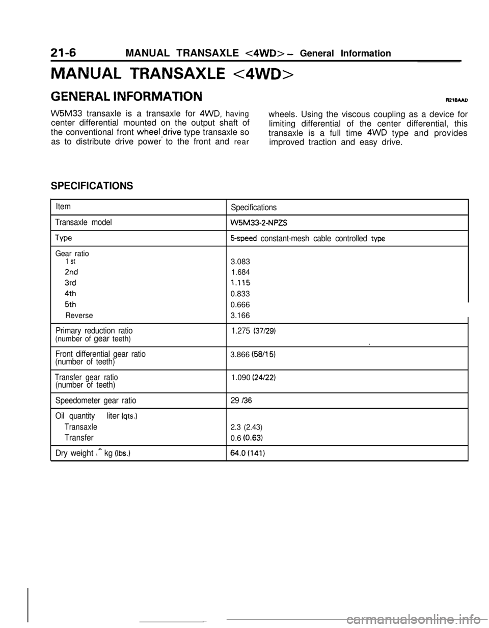
W5M33 transaxle is a transaxle for 4WD, having
center differential mounted on the output shaft ofwheels. Using the viscous coupling as a device for
the conventional front
wheeledrive type transaxle solimiting differential of the center differential, this
as to distribute drive power to the front and reartransaxle is a full time 4WD type and provides
improved traction and easy drive.
SPECIFICATIONS
Item
Transaxle model
We
Gear ratio
1 St
2nd
3rd4th5th
Reverse
Primary reduction ratio
(number of gear teeth)
Front differential gear ratio
(number of teeth)Specifications
W5M33-2-NPZS
5-speed constant-mesh cable controlled type3.083
1.684
7.1150.833
0.666
3.166
1.275 (37/29).
3.866 (58/l
51
Transfer gear ratio(number of teeth)1.090 (24/22)
Speedometer gear ratio
Oil quantity
liter (qts.)
Transaxle
Transfer
Dry weight ic kg (Ibs.)
29 I36
2.3 (2.43)0.6
(0.63)
64.0(141)
Page 336 of 391
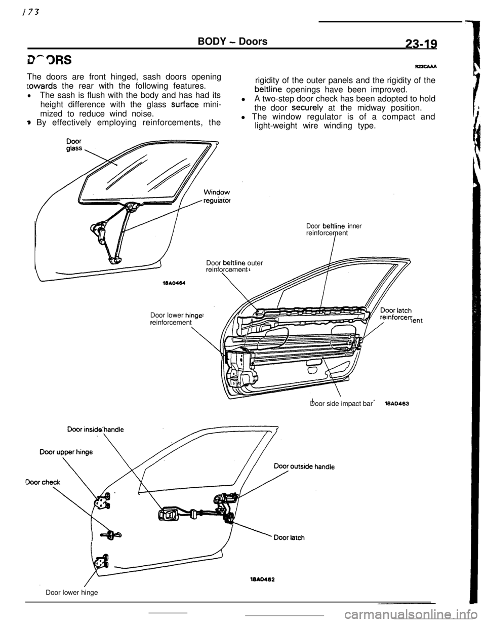
i73BODY
- Doors23-19The doors are front hinged, sash doors opening
Lowards the rear with the following features.
lThe sash is flush with the body and has had its
height difference with the glass
surface mini-
mized to reduce wind noise.
* By effectively employing reinforcements, the
regularorrigidity of the outer panels and the rigidity of thebeltline openings have been improved.
lA two-step door check has been adopted to hold
the door securely at the midway position.
l The window regulator is of a compact and
light-weight wire winding type.
Door beltline innerreinforcement
Door beltline outer
reinforcement
Door lower
hinr-reinforcement *-lentDoor side impact bar
l6A0463
16AO462Door lower hinge
Page 337 of 391
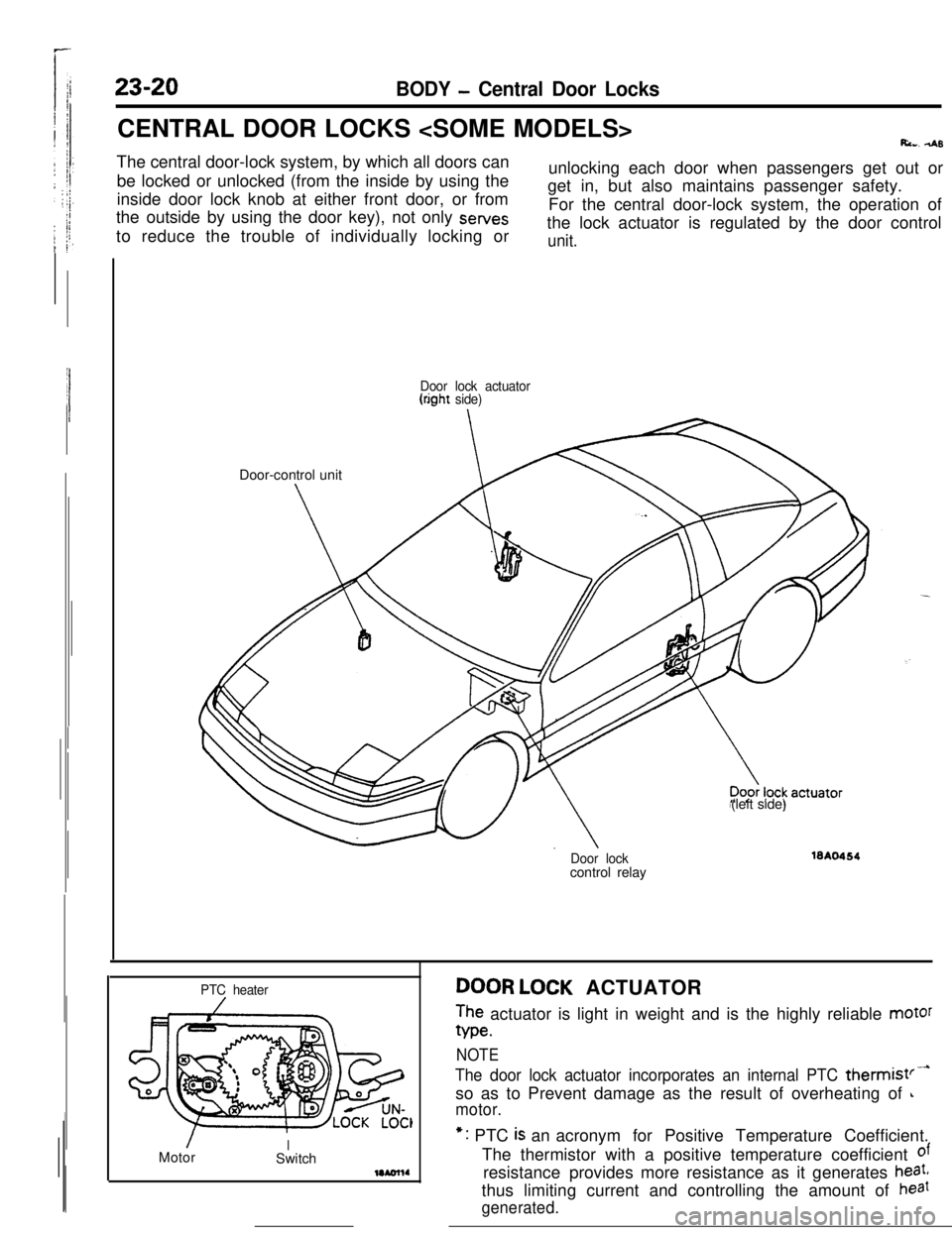
23-20BODY - Central Door LocksCENTRAL DOOR LOCKS
Ri... 4sThe central door-lock system, by which all doors can
be locked or unlocked (from the inside by using the
inside door lock knob at either front door, or from
the outside by using the door key), not only sewes
to reduce the trouble of individually locking orunlocking each door when passengers get out or
get in, but also maintains passenger safety.
For the central door-lock system, the operation of
the lock actuator is regulated by the door control
unit.
Door lock actuator(right side)Door-control unit
(left side)
Door lockcontrol relay16A0464
PTC heater
/MotorISwitchDOOR LOCK ACTUATOR
The actuator is light in weight and is the highly reliable motor
We.
NOTE
The door lock actuator incorporates an internal PTC thermist’-so as to Prevent damage as the result of overheating of
L
motor.*: PTC
is an acronym for Positive Temperature Coefficient.
The thermistor with a positive temperature coefficient
ofresistance provides more resistance as it generates
heat,thus limiting current and controlling the amount of
haat
generated.