heater MITSUBISHI ECLIPSE 1990 Service Manual
[x] Cancel search | Manufacturer: MITSUBISHI, Model Year: 1990, Model line: ECLIPSE, Model: MITSUBISHI ECLIPSE 1990Pages: 391, PDF Size: 15.27 MB
Page 3 of 391
TALON
BACKUP
README.N or for additional information
PreViOUSlVmanufactured.a *-a- .I._..-1-L,.* _____ #Q ^_^__ l L.-Orintul in U.S.A.
GROUP INDEXROSA. - -
General. . . . . . . . . . . . . . . . . . . . . . . . . . . . . .. . . . . . . . . . . . . . . . . .
Front Suspensio n................................
.
Brakes - Eir$rii. . . . . . . . . . . . . . . . . . . . . . . . . . ..s...
Clutch. . . . . . . . . . . . . . . . . . . . . . . . . . . . . . . . . . . . . . . . . . . . . . . . . . . .
Cooling. . . . . . :. . . . .. . . . . . . . . . . . . . . . . . . . . . . . . . . . . . . . . . . .
Electrical. . . . . . . . . . . . . . . . . . . . . . . . . . . ..-..................
Engine....................................................
. . . . . . . . . . . . . . . . . . . . . . . . . . . . . . . . . . . . . . . .
Propeller Shaft and Universal. . . . . . . .
ml
. . . . . . . . . . . . . . . . . . . . . . . . . . . . . . . .
Power steeringCD
ManualTransaxl e - Automatic....................
m
Bodym
Heaters and Air ConditioningRI
A
Emission Control Systems
Page 48 of 391
7-2 COOLIN G- General Information
/ Heater
Radi
Watei pumpMAO1 03
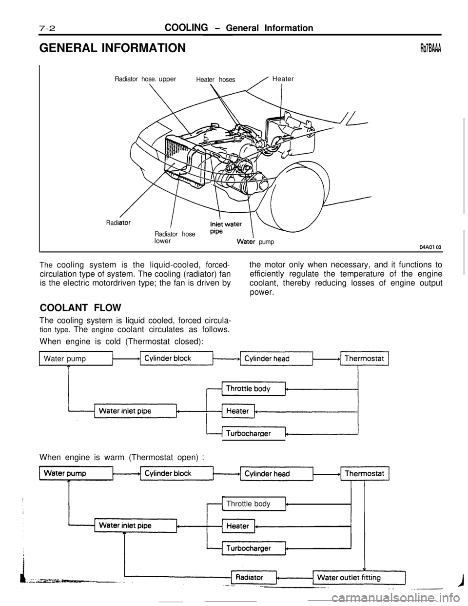
The cooling system is the liquid-cooled , forced-
1
T
+m
I
When engine is warm (Thermostat open) :
Throttle bodyt
Page 55 of 391
ELECTRICAL - Fuses8-3q
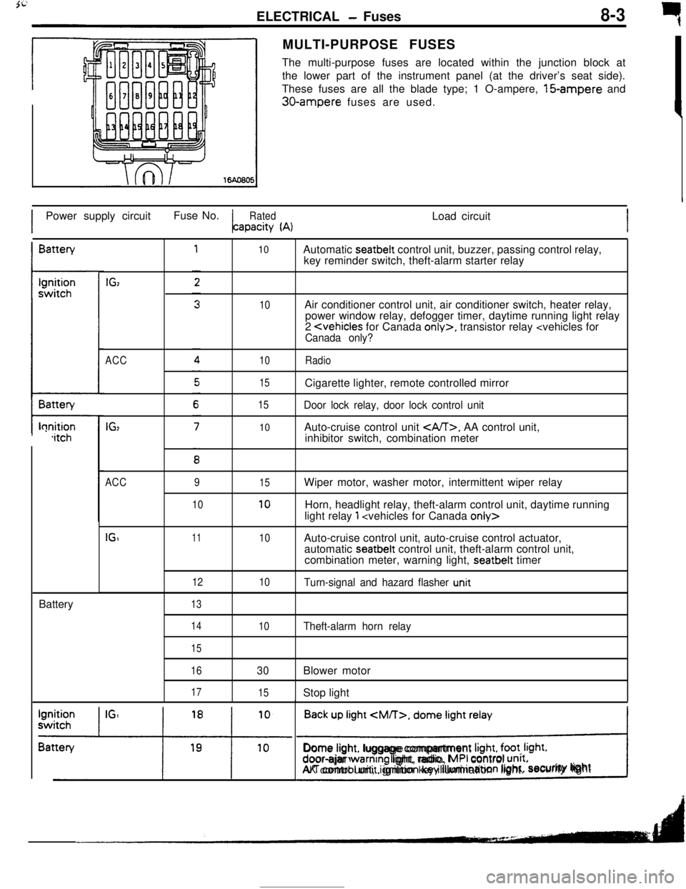
rMULTI-PURPOSE FUSES
The multi-purpose fuses are located within the junction block at
the lower part of the instrument panel (at the driver’s seat side).
These fuses are all the blade type; 1 O-ampere, 15-ampere and
30-ampere fuses are used.
IPower supply circuitFuse No.
RatedLoad circuitapacity
(A)IBattery
t-lonition,itchBattery
IGz
ACC
IG,
10
10
10
15
15
10Automatic seatbelt control unit, buzzer, passing control relay,
key reminder switch, theft-alarm starter relay
Air conditioner control unit, air conditioner switch, heater relay,
power window relay, defogger timer, daytime running light relay
2
Door lock relay, door lock control unitAuto-cruise control unit
, AA control unit,
inhibitor switch, combination meter
ACC
IGI9
1011
12
1315
10
10
10Wiper motor, washer motor, intermittent wiper relay
Horn, headlight relay, theft-alarm control unit, daytime running
light relay
1
automatic seatbelt control unit, theft-alarm control unit,
combination meter, warning light, seatbelt timer
Turn-signal and hazard flasher u.nit
14
15
16
17
10Theft-alarm horn relay
30Blower motor
15Stop light
Back up light
CM/T>, dome light relay
!Dome light. luggage compartment
Irght, foot. Irght.door-ajar warntng light, radio, MPI control unrt.AK control unit, ignition key illumination light.security lightI
Page 57 of 391
3i
ELECTRICAL - Junction Block8-5JUNCTION
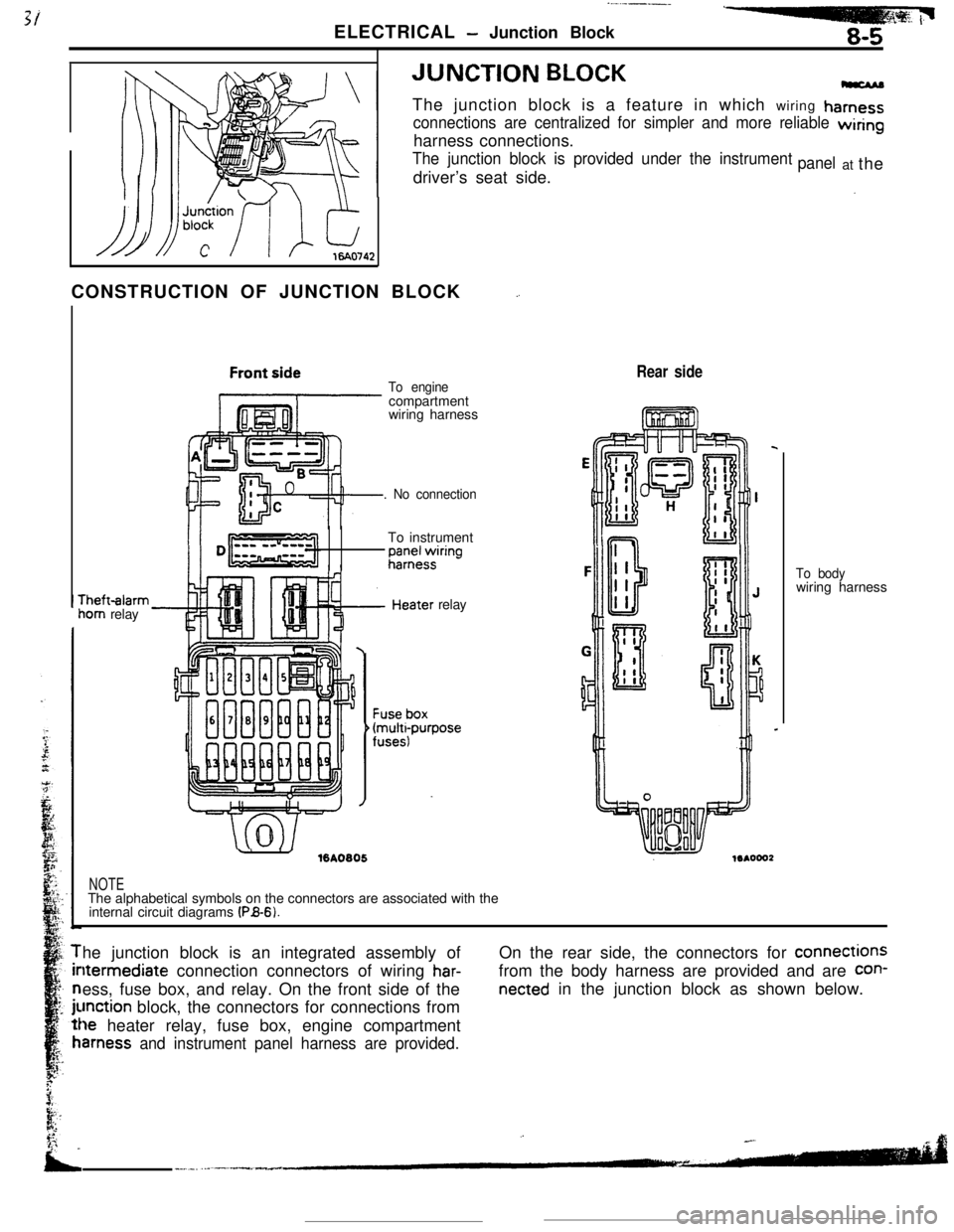
BLOCKThe junction block is a feature in which wiring
hamess
connections are centralized for simpler and more reliable wiringharness connections.
The junction block is provided under the instrumentdriver’s seat side.panelat the
CONSTRUCTION OF JUNCTION BLOCK
_.rheft-alarm
iom relay
To enginecompartment
wiring harness
. No connectionTo instrument
;;;+$ring
.’ ./%A0805relay
Rear side
NOTEThe alphabetical symbols on the connectors are associated with the
internal circuit diagrams
(PB-6).To bodywiring harness
he junction block is an integrated assembly ofltermediate connection connectors of wiring
har-ess, fuse box, and relay. On the front side of the
unction block, the connectors for connections from
le heater relay, fuse box, engine compartment
amess and instrument panel harness are provided.On the rear side, the connectors for connections
from the body harness are provided and are
con-
netted in the junction block as shown below.
Page 63 of 391
1ELECTRICAL
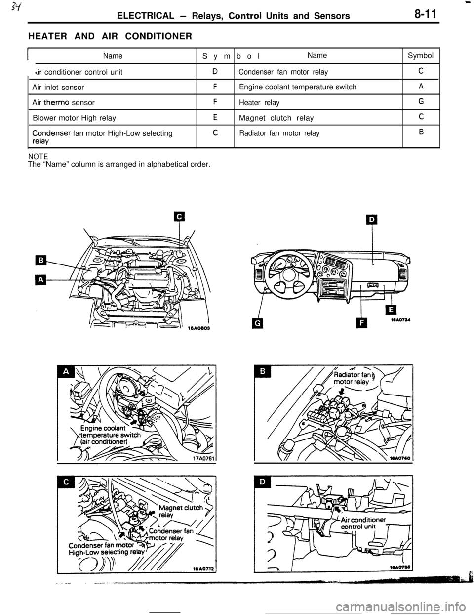
-Relays, Control Units and Sensors8-11HEATER AND AIR CONDITIONER
INameSymbolName
4ir conditioner control unitDCondenser fan motor relayAir inlet sensor
FEngine coolant temperature switch
Air therm0 sensor
FHeater relayBlower motor High relay
EMagnet clutch relay
$x$enser fan motor High-Low selectingCRadiator fan motor relay
NOTEThe “Name” column is arranged in alphabetical order.Symbol
C
A
G
C
B
Page 133 of 391
FUEL SYSTEM - Sensors14-21When exposed to light, the photo diode conducts
urrent in a direction opposite to an ordinary diode.
.s a result, current flows in the direction indicated
by the arrow and dotted line and a voltage (5 volts) isapplied to the comparator of the sensor unit so that
the terminal voltage of the engine control unit
becomes 5 volts. When the disc rotates further andthe slit moves beyond the space between the
LED/photo diode pair, the light can no longer reach
the photo diode, thus the current indicated by the
dotted line ceases to flow and the terminal voltage
of the engine control unit becomes 0 volt.
tn this
way, pulse signals are sent to the engine control
unit from the sensor unit.
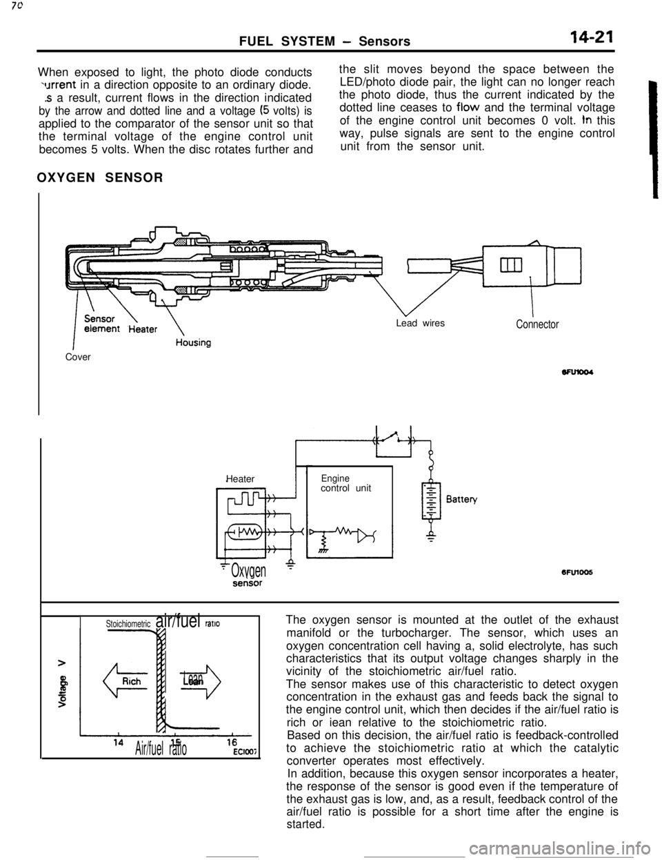
OXYGEN SENSOR
k
1 ~~~~t13ate~ousingCoverLead wiresConnectorHeater
Enginecontrol unit6FUlOO5
- Oxygen‘-serisor
The oxygen sensor is mounted at the outlet of the exhaust
manifold or the turbocharger. The sensor, which uses an
oxygen concentration cell having a, solid electrolyte, has such
characteristics that its output voltage changes sharply in the
vicinity of the stoichiometric air/fuel ratio.
The sensor makes use of this characteristic to detect oxygen
concentration in the exhaust gas and feeds back the signal to
the engine control unit, which then decides if the air/fuel ratio is
rich or iean relative to the stoichiometric ratio.
Based on this decision, the air/fuel ratio is feedback-controlled
to achieve the stoichiometric ratio at which the catalytic
converter operates most effectively.
In addition, because this oxygen sensor incorporates a heater,
the response of the sensor is good even if the temperature of
the exhaust gas is low, and, as a result, feedback control of the
air/fuel ratio is possible for a short time after the engine is
started.
Stoichiometric air/fuel ratlo
r3
Lean
Air/fuel ratioEC1007
Page 271 of 391
AUTOMATIC TRANSAXLE - Transaxle Control21-47
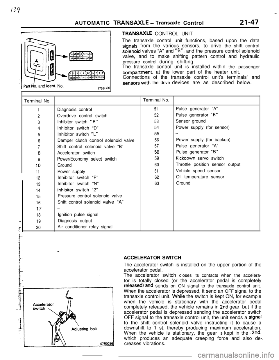
+TFWNSAXLE CONTROL UNIT
Part b!o. and Ident. No.17504The transaxle control unit functions, based upon the data
signals from the various sensors, to drive the shift controlsolenoid valves “A” and
“B”, and the pressure control solenoid
valve, and to make shifting pattern control and hydraulic
pressure control during shifting.
The transaxle control unit is installed within the passengercompartment, at the lower part of the heater unit.
Connections of the transaxle control unit’s terminals” and
sensors with the drive devices are as described below.
Terminal No.Terminal No.
1Diagnosis control51Pulse generator “A”
2Overdrive control switch52Pulse generator “B”
3Inhibitor switch e R U53Sensor ground
4Inhibitor switch “D”
54Power supply (for sensor)
5Inhibitor switch “L”55 -
6Damper clutch control solenoid valve56Power supply (for backup)
7Shift control solenoid valve “B”57Pulse generator “A”
8Accelerator switch58Pulse generator “B”
9Power/Economy select switch59Kickdown servo switch
10Ground60Throttle position sensor output
11Power supply61Vehicle speed sensor
12Inhibitor switch “P”62Oil temperature sensor
13Inhibitor switch “N”63Ground
14inhibitor switch “2”
15Pressure control solenoid valve
16Shift control solenoid valve “A”
17
-
18Ignition pulse signal
19Diagnosis output
20Air conditioner relay signal
rACCELERATOR SWITCH
The accelerator switch is installed on the upper portion of the
accelerator pedal.
The accelerator switch closes its contacts when the accelera-
tor is totally closed (or the accelerator pedal is completelyreieasedj‘and sends on ON signal to the transaxle control unit.
When the accelerator is depressed, it send an OFF signal to the
transaxle control unit. Whiie the switch is kept ON, for example
when the vehicle is stationary with the accelerator pedal
completely released, the vehicle remains in
2nd gear, but if the
accelerator pedal is depressed sending the accelerator switch
OFF signal to the transaxle control unit, the unit sends a signal
to the shift control solenoid valve instructing it to cause a
downshift to 1 st, thereby producing maximum acceleration.
When the vehicle is stationary, the gear is kept in the .2nd,
which produces an adequate creeping force and also de-.
creases vibrations.
Page 337 of 391
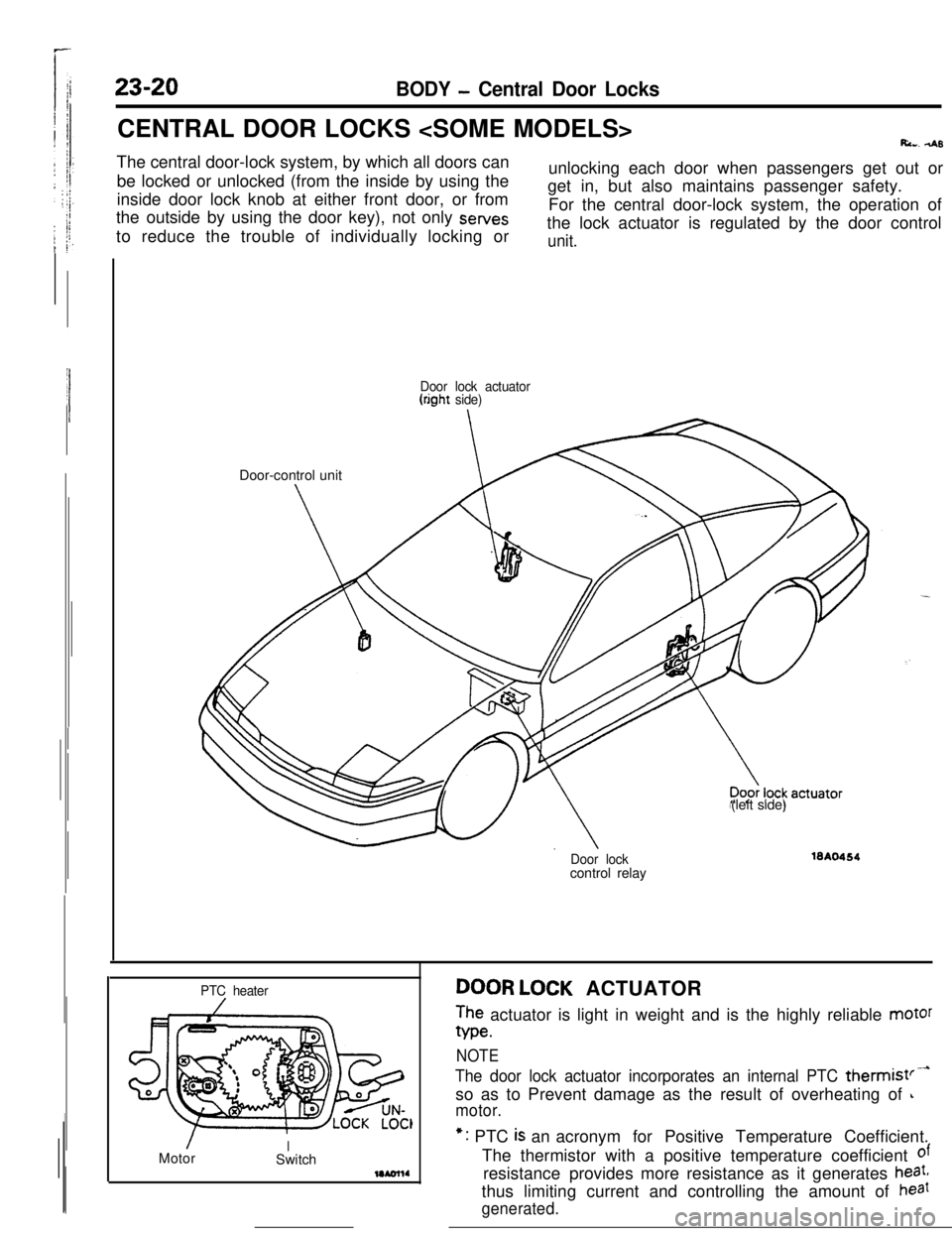
23-20BODY - Central Door LocksCENTRAL DOOR LOCKS
Ri... 4sThe central door-lock system, by which all doors can
be locked or unlocked (from the inside by using the
inside door lock knob at either front door, or from
the outside by using the door key), not only sewes
to reduce the trouble of individually locking orunlocking each door when passengers get out or
get in, but also maintains passenger safety.
For the central door-lock system, the operation of
the lock actuator is regulated by the door control
unit.
Door lock actuator(right side)Door-control unit
(left side)
Door lockcontrol relay16A0464
PTC heater
/MotorISwitchDOOR LOCK ACTUATOR
The actuator is light in weight and is the highly reliable motor
We.
NOTE
The door lock actuator incorporates an internal PTC thermist’-so as to Prevent damage as the result of overheating of
L
motor.*: PTC
is an acronym for Positive Temperature Coefficient.
The thermistor with a positive temperature coefficient
ofresistance provides more resistance as it generates
heat,thus limiting current and controlling the amount of
haat
generated.
Page 364 of 391
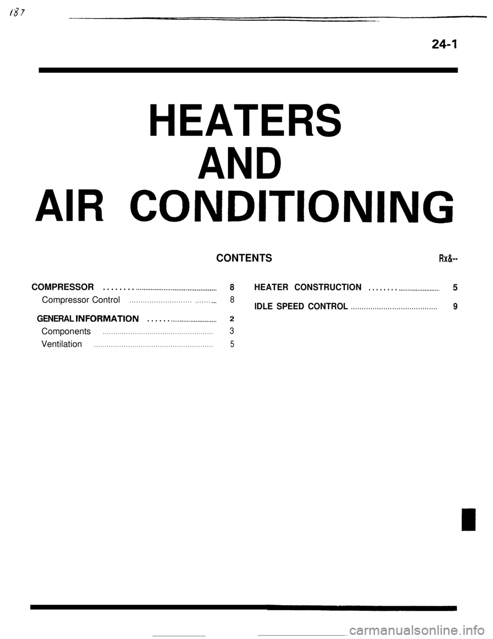
24-1
HEATERS
CONDITIONING
CONTENTS Rx&--
.._.........I............................... 8 HEATER CONSTRUCTIO N. . . . . . . . .._..................... 5
Compressor Control . . . . . . . . . . . . . . . . . . . . . . . . . . . . _ . . . . . . .._.. 8IDLE SPEED CONTRO L. . . . . . . . . . . . . . . . . . . . . . . . . . . . . . . . . . . . \
. . . . 9
tNFORMATt0N. . . . . . .._................_......2
Page 365 of 391
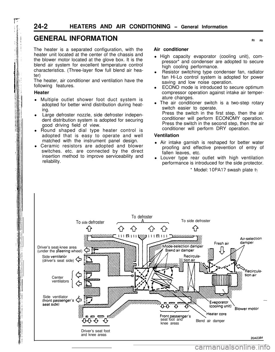
24-2 HEATERS AND AIR CONDITIONING
1 OPA17 swash plate t:
To defroster
/A\To side defroster
9G-3 53033
ventilators
‘lo’
Driver’s seat-knee area3$
(under the fieering wheel)b
Side ventilatbr(driver’s seat side) G
Center
20A03M