wiring MITSUBISHI ECLIPSE 1990 Service Manual
[x] Cancel search | Manufacturer: MITSUBISHI, Model Year: 1990, Model line: ECLIPSE, Model: MITSUBISHI ECLIPSE 1990Pages: 391, PDF Size: 15.27 MB
Page 57 of 391

3i
ELECTRICAL - Junction Block8-5JUNCTION
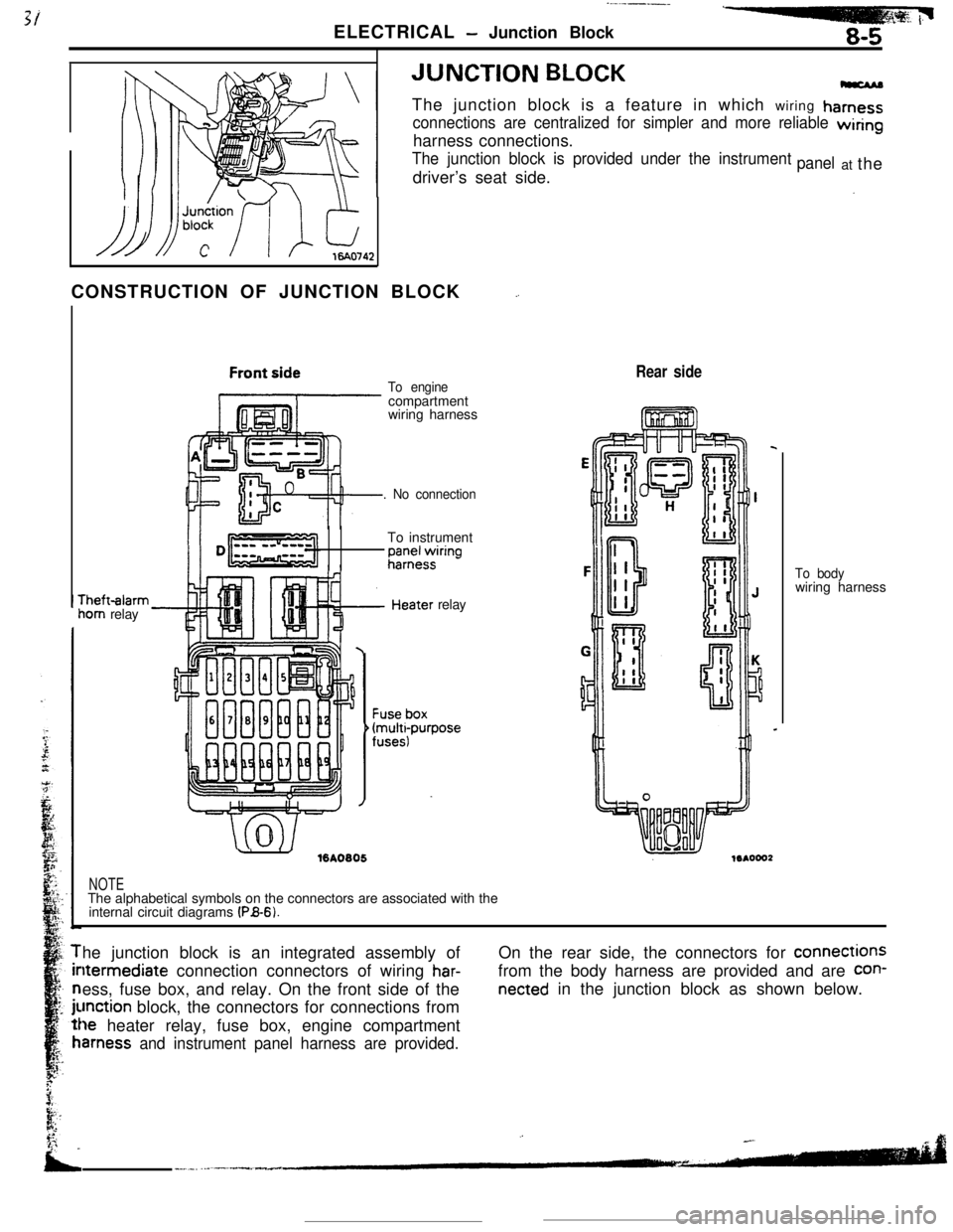
BLOCKThe junction block is a feature in which wiring
hamess
connections are centralized for simpler and more reliable wiringharness connections.
The junction block is provided under the instrumentdriver’s seat side.panelat the
CONSTRUCTION OF JUNCTION BLOCK
_.rheft-alarm
iom relay
To enginecompartment
wiring harness
. No connectionTo instrument
;;;+$ring
.’ ./%A0805relay
Rear side
NOTEThe alphabetical symbols on the connectors are associated with the
internal circuit diagrams
(PB-6).To bodywiring harness
he junction block is an integrated assembly ofltermediate connection connectors of wiring
har-ess, fuse box, and relay. On the front side of the
unction block, the connectors for connections from
le heater relay, fuse box, engine compartment
amess and instrument panel harness are provided.On the rear side, the connectors for connections
from the body harness are provided and are
con-
netted in the junction block as shown below.
Page 176 of 391
![MITSUBISHI ECLIPSE 1990 Service Manual 14-64FUEL SYSTEM - Auto-cruise Control System
FixedAccelera-FixedSpeed -c tion-LC speed
High
Vehic’e iapprox. 40 km/hspeedG!5 mph) or hagher]Low
’When the RESUME
(ACCEL) Switch is Kept Turned
Whi MITSUBISHI ECLIPSE 1990 Service Manual 14-64FUEL SYSTEM - Auto-cruise Control System
FixedAccelera-FixedSpeed -c tion-LC speed
High
Vehic’e iapprox. 40 km/hspeedG!5 mph) or hagher]Low
’When the RESUME
(ACCEL) Switch is Kept Turned
Whi](/img/19/57103/w960_57103-175.png)
14-64FUEL SYSTEM - Auto-cruise Control System
FixedAccelera-FixedSpeed -c tion-LC speed
High
Vehic’e iapprox. 40 km/hspeedG!5 mph) or hagher]Low
’When the RESUME
(ACCEL) Switch is Kept Turned
While the RESUME switch is ON, the actuator’s DC
mote,caused to rotate to the PULL side; the vehicle speed when the
switch is switched OFF as acceleration continues is entered in
the memory, and is thereafter controlled as the fixed speed.
CANCELLATION
When, during fixed-speed driving, the signals described below
are input, conductivity to the electromagnetic clutch is inter-
rupted, thus
cancelling the auto-cruise control system.
l Stop light switch ON (brake pedal depressed)
l Clutch switch ON (clutch pedal depressed)
lInhibitor switch ON (selector lever at
“P” or “N” position)
LOW-SPEED LIMIT
There is automatic cancellation at or below the low-speed limit
vehicle speed [approximately 40 km/h (25 mph)].
HIGH-SPEED LIMIT
The vehicle cannot be driven at a fixed speed which is at or
higher than the high-speed limit [approximately 145 km/h
(90
mph)l.Note that the vehicle speed memorized when the SET switch
a5pressed while the vehicle is traveling at the high-speed limit or
higher
vvill be the high-speed limit vehicle speed.
FAIL-SAFE FUNCTION
When the following situations are encountered during fixed-
speed driving, the signals to interrupt, conductivity to the
electromagnetic clutch are input, thus canceling the auto-cruise
control system.
0
0
0When vehicle speed decreases to the low-speed limit
[approx. 40 km/h (25 mph)].
If the vehicle speed decreases to a speed which is
approximately 20 km/h (12 mph) or more below ‘the
memorized vehicle speed.
When the vehicle speed drops by 20 km/h
(12 mph) or more
after having reached the set speed -10 km/h (-6 mph) in
the RESUME mode.
If there is damaged or disconnected wiring of the input line
(stop light switch load side) of the stop light switch.
if there is no input of the vehicle speed signal for a certain
fixed time (1 second or longer).
If the SET and RESUME control switches are switched ON
at the same time.
If the cancel switches (stop light switch, clutch switch or
inhibitor switch) and command switches (SET switch
orRESUME switch) are switched ON at the same time.
if the actuator clutch driver (transistor) of the control unk
remains ON (short-circuit).
Page 181 of 391

FUEL SYSTEM- Auto-cruise Control System14-69
ni2nnncisv,“y’I”“.-
connectorDiagnosis Display Patterns and Codes
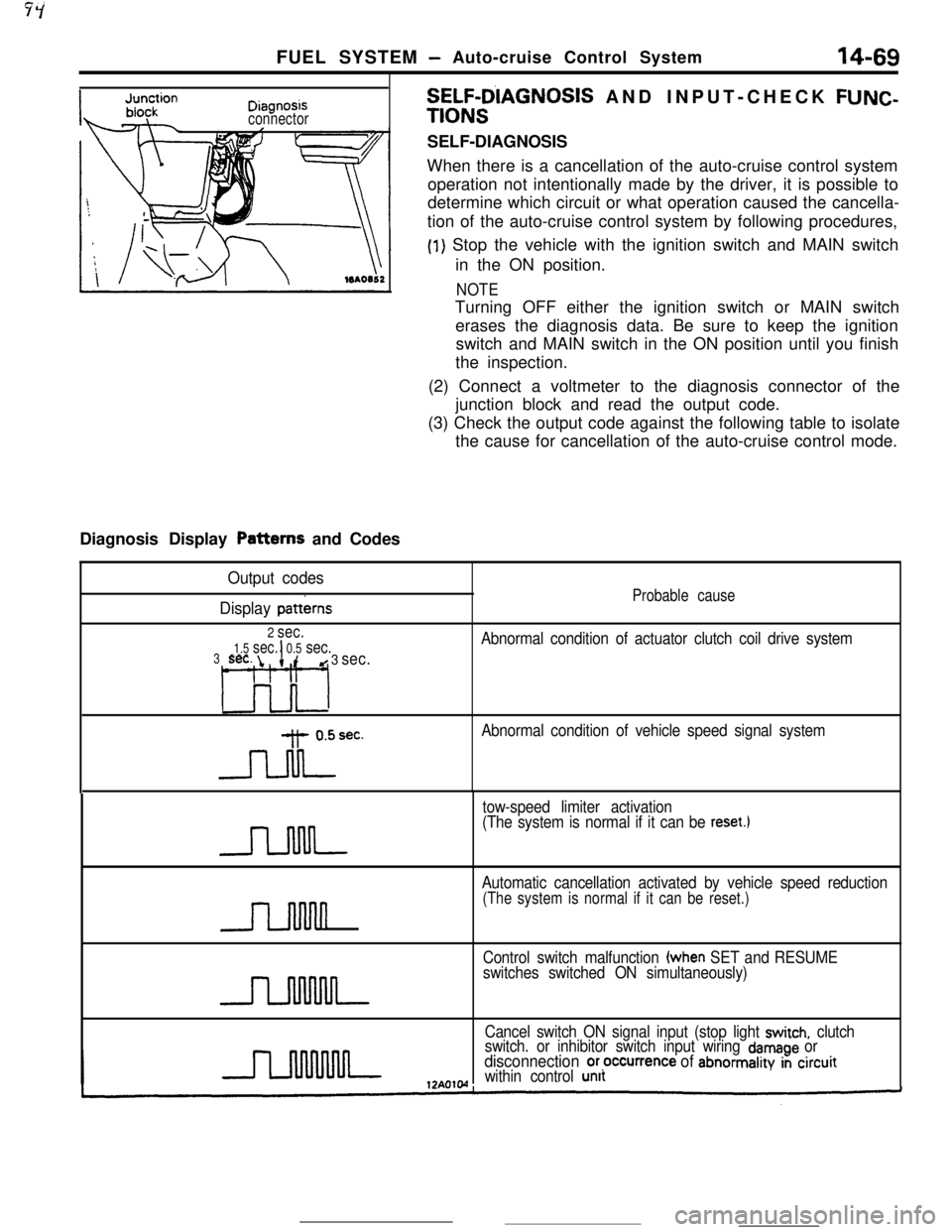
SELF-D’IAGNOSIS AND INPUT-CHECK FUNC-
TIONSSELF-DIAGNOSIS
When there is a cancellation of the auto-cruise control system
operation not intentionally made by the driver, it is possible to
determine which circuit or what operation caused the cancella-
tion of the auto-cruise control system by following procedures,
(1) Stop the vehicle with the ignition switch and MAIN switch
in the ON position.
NOTETurning OFF either the ignition switch or MAIN switch
erases the diagnosis data. Be sure to keep the ignition
switch and MAIN switch in the ON position until you finish
the inspection.
(2) Connect a voltmeter to the diagnosis connector of the
junction block and read the output code.
(3) Check the output code against the following table to isolate
the cause for cancellation of the auto-cruise control mode.
Output codes
Display
patterns
2 sec.
1.5 sec.I0.5 sec.3sec. id 3 sec.
L3o-l
-Jdrec.
Probable cause
Abnormal condition of actuator clutch coil drive system
Abnormal condition of vehicle speed signal system
tow-speed limiter activation
(The system is normal if it can be
reset.1
n
Automatic cancellation activated by vehicle speed reduction
(The system is normal if it can be reset.)
Control switch malfunction (when SET and RESUME
switches switched ON simultaneously)
Cancel switch ON signal input (stop light
switch, clutch
switch. or inhibitor switch input wiring damage ordisconnection or,occurrence of abnormality in circuitwithin control unit
Page 278 of 391

-21-54AUTOMATIC TRANSAXLE
- Transaxle Control
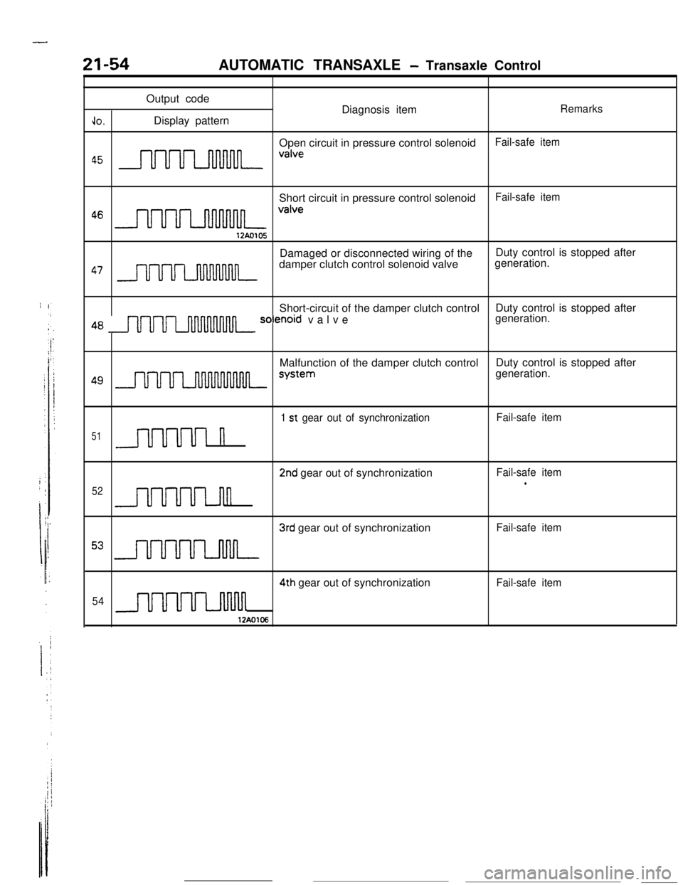
Output code
Diagnosis item
Remarks
JO.Display pattern
Open circuit in pressure control solenoid
Fail-safe item
a5 nnnn valveShort circuit in pressure control solenoid
Fail-safe item
46 m valve12A0105Damaged or disconnected wiring of theDuty control is stopped after
47 nnru7_nnnnnnndamper clutch control solenoid valvegeneration.
Short-circuit of the damper clutch controlDuty control is stopped after
48 m solenord valvegeneration.
Malfunction of the damper clutch controlDuty control is stopped after
49 J- systemgeneration.
1 st gear out of synchronizationFail-safe item
51n
2nd gear out of synchronizationFail-safe iteml52n
3rd gear out of synchronizationFail-safe item
53 m4th gear out of synchronization
Fail-safe item
54
uuum12Ao106
Page 318 of 391

--
,
; ’I :j:.
i
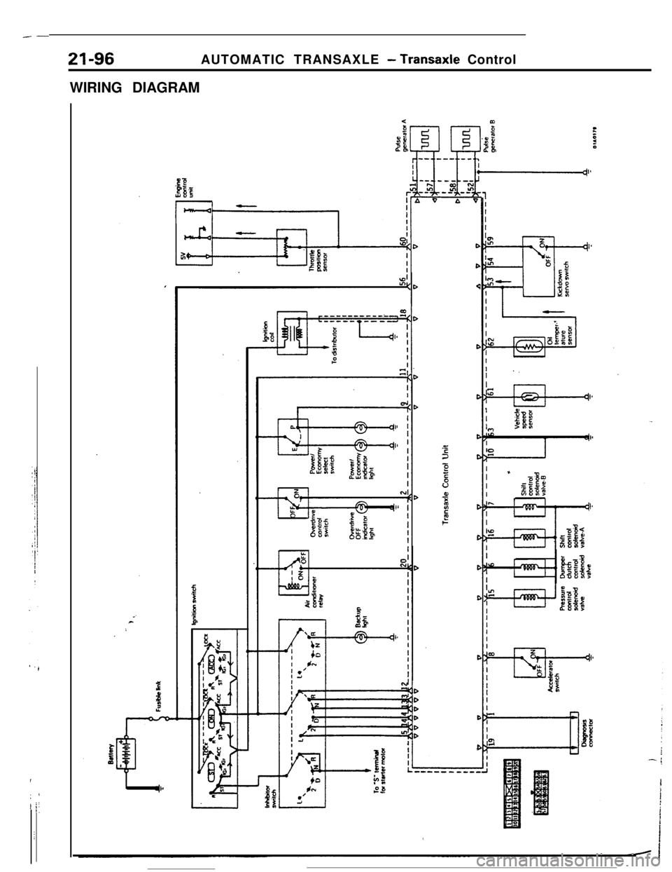
-21-96AUTOMATIC TRANSAXLE
- Transaxle Control
WIRING DIAGRAMDD<
D
C
C
22C
2
5v0,‘ii2t6c
C
C
C
C
C
C