steering MITSUBISHI ECLIPSE 1990 Service Manual
[x] Cancel search | Manufacturer: MITSUBISHI, Model Year: 1990, Model line: ECLIPSE, Model: MITSUBISHI ECLIPSE 1990Pages: 391, PDF Size: 15.27 MB
Page 3 of 391
TALON
BACKUP
README.N or for additional information
PreViOUSlVmanufactured.a *-a- .I._..-1-L,.* _____ #Q ^_^__ l L.-Orintul in U.S.A.
GROUP INDEXROSA. - -
General. . . . . . . . . . . . . . . . . . . . . . . . . . . . . .. . . . . . . . . . . . . . . . . .
Front Suspensio n................................
.
Brakes - Eir$rii. . . . . . . . . . . . . . . . . . . . . . . . . . ..s...
Clutch. . . . . . . . . . . . . . . . . . . . . . . . . . . . . . . . . . . . . . . . . . . . . . . . . . . .
Cooling. . . . . . :. . . . .. . . . . . . . . . . . . . . . . . . . . . . . . . . . . . . . . . . .
Electrical. . . . . . . . . . . . . . . . . . . . . . . . . . . ..-..................
Engine....................................................
. . . . . . . . . . . . . . . . . . . . . . . . . . . . . . . . . . . . . . . .
Propeller Shaft and Universal. . . . . . . .
ml
. . . . . . . . . . . . . . . . . . . . . . . . . . . . . . . .
Power steeringCD
ManualTransaxl e - Automatic....................
m
Bodym
Heaters and Air ConditioningRI
A
Emission Control Systems
Page 8 of 391
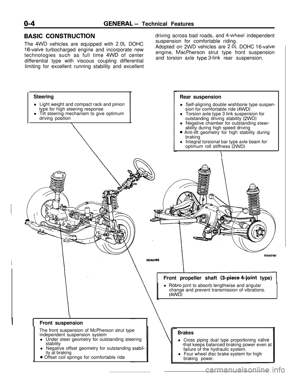
o-4GENERAL - Technical Features
BASIC CONSTRUCTION
The 4WD vehicles are equipped with
2.OL DOHC
16-valve turbocharged engine and incorporate new
technologies such as full time 4WD of center
differential type with viscous coupling differential
limiting for excellent running stability and excellent
Steering
l Light weight and compact rack and pinion
type for high steering response
l Tilt steering mechanism to give optimum
driving position
\driving across bad roads, and $-wheel independent
suspension for comfortable riding.
Adopted on
2WD vehicles are 2.OL DOHC 16-valveengine, MacPherson strut type front suspension
and torsion axle
typ.e 3-link rear suspension.
Rear suspension
l Self-aligning double wishbone type suspen-
sion for comfortable ride
(4WD)l Torsion axle type 3 link suspension for
outstanding driving stability
(2WD)l Negative chamber for outstanding steer-
ability during high speed driving
0 Anti-lift geometry for high stability duringbraking
lIntegral torsional bar type axle beam for
optimum roll stiffness (2WD)
\Front propeller shaft (3-piece
4-joint type)
lRobro joint to absorb lengthwise and angular
change and prevent transmission of vibrations.
(4WD)
IFront suspension
The front suspension of McPherson strut type
independent suspension system
l Under steer geometry for outstanding steering
stability
l Negative offset geometry for outstanding
stabil-ity at braking
0 Offset coil springs for comfortable ride
Brakes
l Cross piping dual type proportioning valvethat keeps balanced braking power even at
failure of the hydraulic system.
l Four wheel disc brake system for high
braking power.
Page 18 of 391
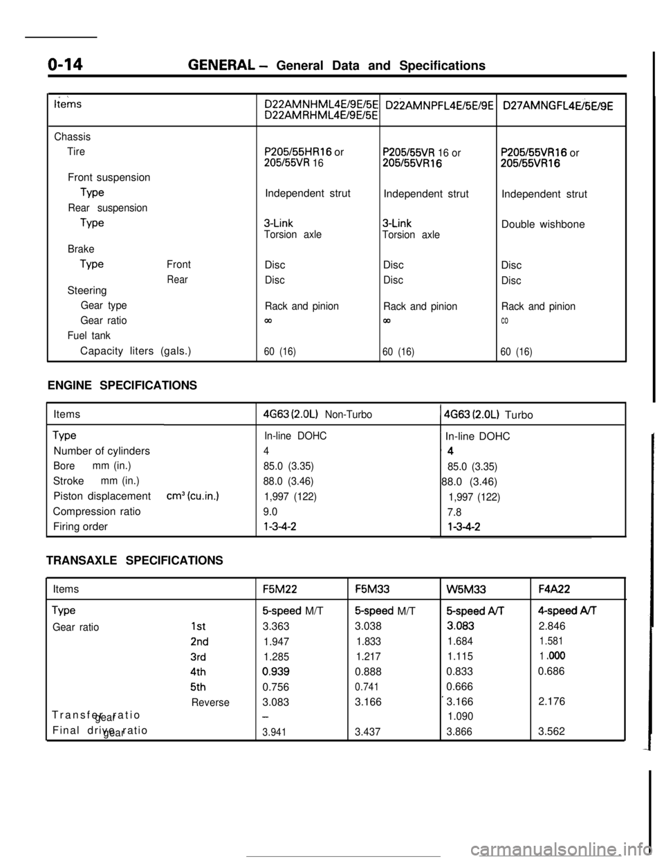
o-14GENERAL - General Data and Specifications
tiems
Chassis
TireFront suspension
Type
Rear suspensionType
Brake
TypeFront
RearSteering
Gear type
Gear ratio
Fuel tankCapacity liters (gals.)
P205/55HR16 or
205l55VR 16Independent strut
3-Link
Torsion axleDisc
Disc
Rack and pinion
m
60 (16)
P205/55VR 16 or205155VR16Independent strut
3-Link
Torsion axleDisc
Disc
Rack and pinion
00
60 (16)
P205155VR16 or205155VR16Independent strut
Double wishbone
Disc
Disc
Rack and pinion
co
60 (16)ENGINE SPECIFICATIONS
Items
TypeNumber of cylinders
Boremm (in.)Stroke
mm (in.)Piston displacement
Compression ratio
Firing order
cm3 (cu.in.)
4G63 (2.OL) Non-Turbo1 4663 (2.OL) Turbo
In-line DOHC~ In-line DOHC
4‘4
85.0 (3.35)
85.0 (3.35)
88.0 (3.46)88.0 (3.46)
1,997 (122)
1,997 (122)
9.0
7.8l-3-4-2l-3-4-2
TRANSAXLE SPECIFICATIONS
Items
Type
Gear ratioTransfer ratio
gearFinal drive ratio
gear
1st
2nd
3rd4th5th
ReverseF5M22F5M33
W5M33F4A22
5-speed M/T5-speed M/T&speed ArF4-speed AiT
3.3633.038
3.0832.846
1.9471.8331.6841.581
1.2851.2171.1151 .ooo0.9390.8880.8330.686
0.756
0.7410.666
3.0833.166
’3.1662.176
-1.090
3.9413.4373.8663.562
Page 115 of 391
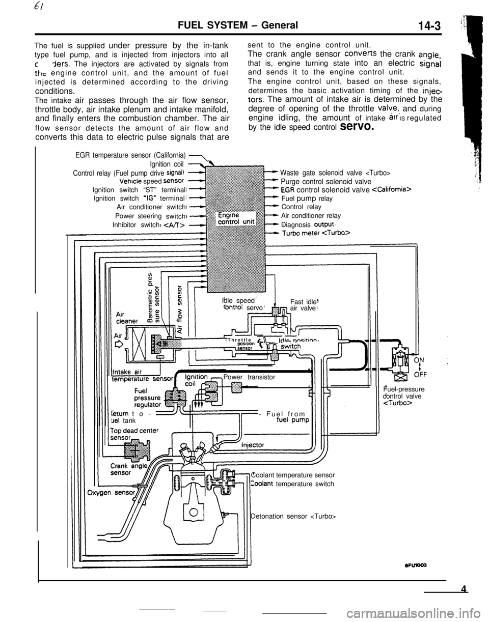
FUEL SYSTEM - General14-3The fuel is supplied under pressure by the in-tanksent to the engine control unit.
type fuel pump, and is injected from injectors into allThe crank angle sensor converts the crank
angle,
cders. The injectors are activated by signals fromthat is, engine turning state into an electric signal
tk, engine control unit, and the amount of fueland sends it to the engine control unit.
injected is determined according to the drivingThe engine control unit, based on these signals,
conditions.determines the basic activation timing of the
injec-The intake air passes through the air flow sensor,
tars. The amount of intake air is determined by the
throttle body, air intake plenum and intake manifold,degree of opening of the throttle
valye,, and during
and finally enters the combustion chamber. The airengine idling, the amount of intake
arr IS regulated
flow sensor detects the amount of air flow and
by the idle speed control servo.converts this data to electric pulse signals that are
EGR temperature sensor (California) 7
Waste gate solenoid valve
Purge control solenoid valve
EGR control solenoid valve
Control relay
Air conditioner relay
Diagnosis output
Ignition coil
Control relay (Fuel pump drive
signal)Vehicle speed
SensorIgnition switch “ST” terminal
Ignition switch
‘IG” terminal
Air conditioner switch
Power steering
switch
Inhibitor switch
Idle speed
ontrol servoFast idle
air valve
-Throttle
&r -kilo m-i&inn’Power transistorleturn to-
uel tank- Fuel from
Coolant temperature sensor
Coolant temperature switchFuel-pressure
control valve
4
Page 126 of 391
14-14
.._~- ---.FUEL SYSTEM
- Sensors
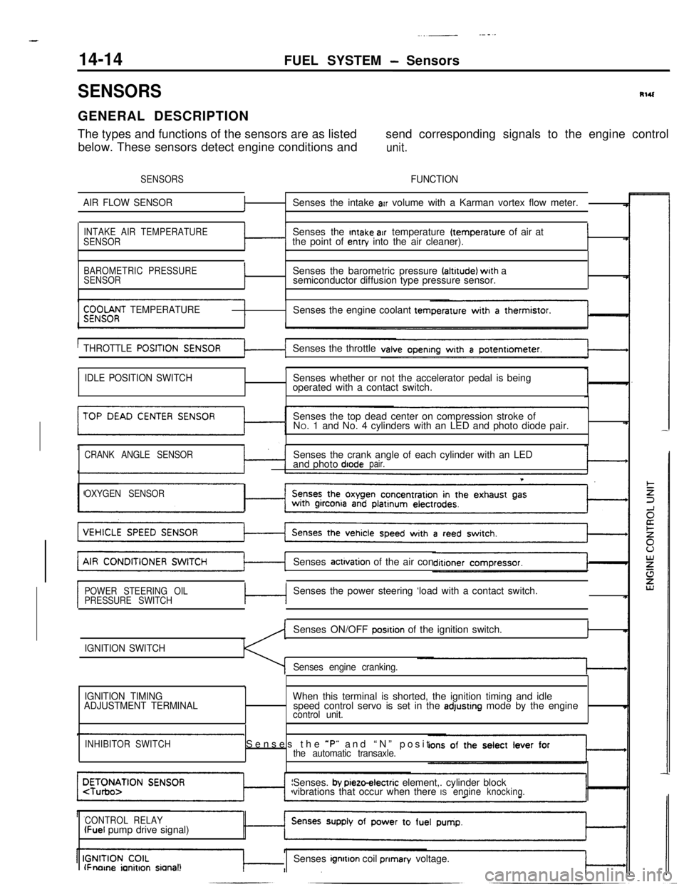
SENSORSRlUGENERAL DESCRIPTION
The types and functions of the sensors are as listedsend corresponding signals to the engine control
below. These sensors detect engine conditions and
unit.
SENSORSFUNCTION
AIR FLOW SENSOR
fSenses the intake arr volume with a Karman vortex flow meter.
INTAKE AIR TEMPERATURE
SENSORSenses the Intake air temperature (temperature of air at
the point of entry into the air cleaner).I
BAROMETRIC PRESSURE
SENSORISenses the barometric pressure faltrtude) wrth a
semiconductor diffusion type pressure sensor.
$;;OOf;T TEMPERATURESenses the engine coolant tern
THROTTLE
POSITISenses the throttle
tI
IDLE POSITION SWITCHSenses whether or not the accelerator pedal is being
operated with a contact switch.
Senses the top dead center on compression stroke of
NO. 1 and No. 4 cylinders with an LED and photo diode pair.
CRANK ANGLE SENSORSenses the crank angle of each cylinder with an LED
and photo diodepair.
T
OXYGEN SENSORSenses
actrvation of the air con
POWER STEERING OIL
PRESSURE SWITCHc-lSenses the power steering ‘load with a contact switch.
IGNITION SWITCHSenses ON/OFF
posrtion of the ignition switch.I
Senses engine cranking.
,
IGNITION TIMING
ADJUSTMENT TERMINALWhen this terminal is shorted, the ignition timing and idle
speed control servo is set in the adjustrng mode by the enginecontrol unit.
INHIBITOR SWITCHSenses the *P” and “N” positthe automatic transaxle.Senses.
by pieto-electric element,. cylinder block
vibrations that occur when there ISengineknocking.
CONTROL RELAY
(Fuel pump drive signal)
lFnorne ianitron sianal!Senses ignrtton coil prIman/ voltage.
Page 136 of 391
--
,
14-24FUEL SYSTEM - Sensors
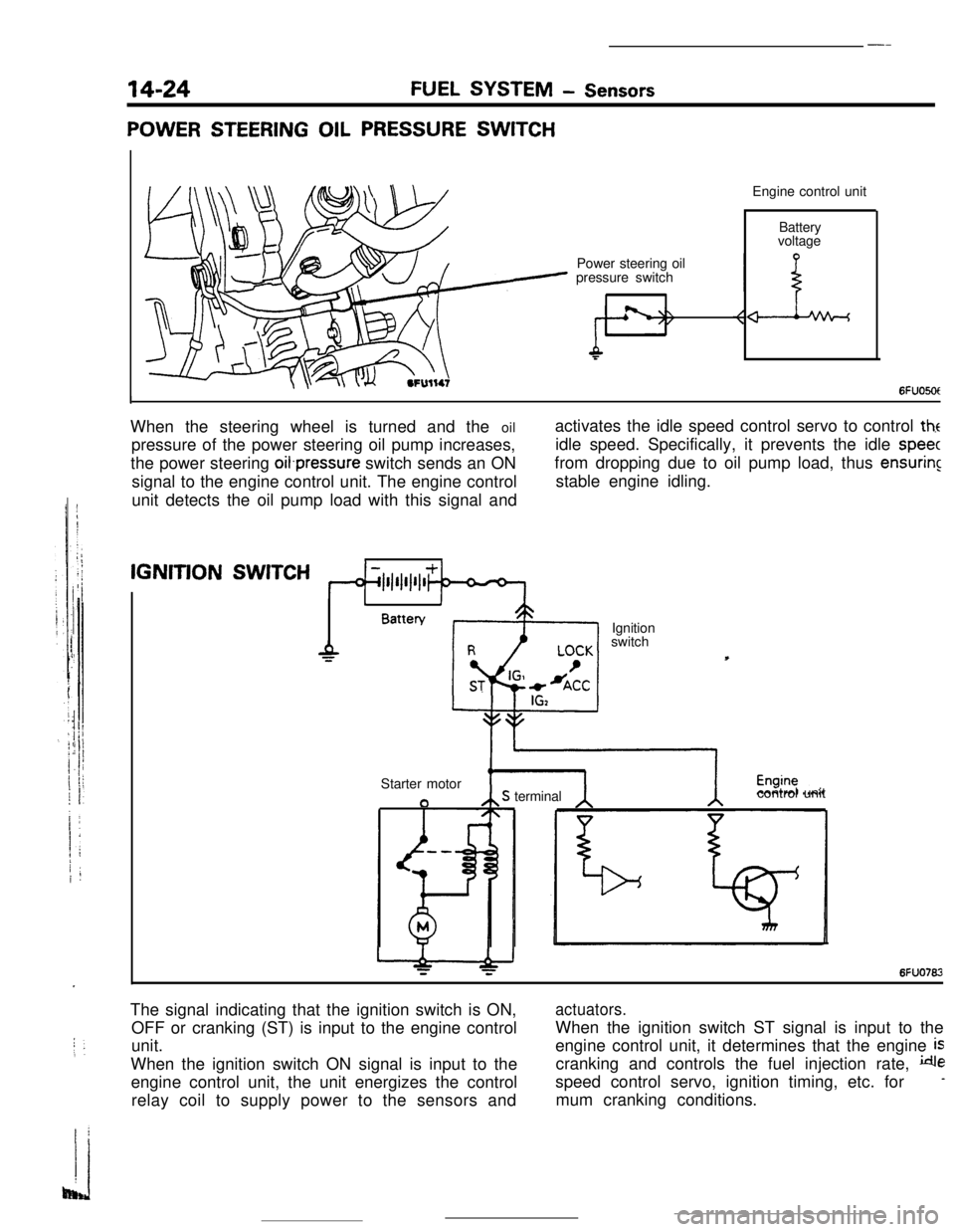
POWER STEERING OIL PRESSURE SWITCHEngine control unit
Power steering oil
pressure switchBattery
voltage
6FUO5OtIWhen the steering wheel is turned and the oil
pressure of the power steering oil pump increases,
the power steering oifpressure switch sends an ON
signal to the engine control unit. The engine control
unit detects the oil pump load with this signal andactivates the idle speed control servo to control
theidle speed. Specifically, it prevents the idle
speecfrom dropping due to oil pump load, thus
ensuringstable engine idling.IGNITION
SWITCH
1IBattery
Ignition
switch
Starter motor
aS terminalcontrol unit
6FUO762The signal indicating that the ignition switch is ON,
OFF or cranking (ST) is input to the engine control
unit.
When the ignition switch ON signal is input to the
engine control unit, the unit energizes the control
relay coil to supply power to the sensors and
actuators.When the ignition switch ST signal is input to the
engine control unit, it determines that the engine
iscranking and controls the fuel injection rate,
despeed control servo, ignition timing, etc. for
-mum cranking conditions.
Page 141 of 391
FUEL SYSTEM- Engine Control Unit14-29
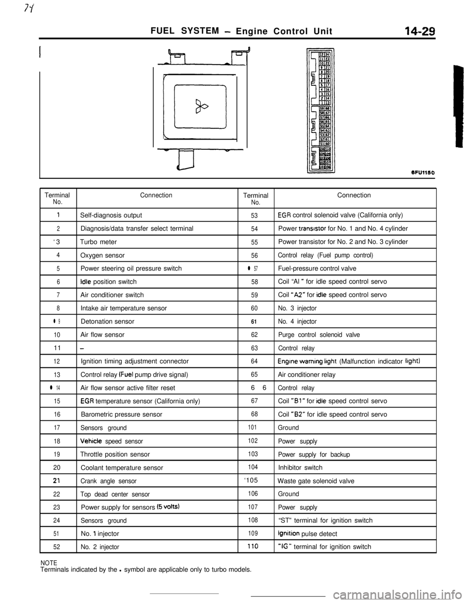
SFUllSOTerminal
ConnectionTerminalConnectionNo.
No.
1Self-diagnosis output53EGR control solenoid valve (California only)
2Diagnosis/data transfer select terminal54Power transrstor for No. 1 and No. 4 cylinder
‘3Turbo meter
55Power transistor for No. 2 and No. 3 cylinder
4Oxygen sensor56Control relay (Fuel pump control)
5Power steering oil pressure switchl 57Fuel-pressure control valve
6Idle position switch58Coil “Al ” for idle speed control servo
7Air conditioner switch59Coil “A2” for idle speed control servo
8Intake air temperature sensor60No. 3 injector
l 9Detonation sensor61No. 4 injector
10Air flow sensor62Purge control solenoid valve11
-63Control relay
12Ignition timing adjustment connector64Engine warning irght (Malfunction indicator light)
13Control relay (Fuel pump drive signal)65Air conditioner relay
l 14Air flow sensor active filter reset66Control relay
15EGR temperature sensor (California only)67Coil “Bl ” for idle speed control servo
16Barometric pressure sensor68Coil “B2” for idle speed control servo
17Sensors ground101Ground
18Vehicle speed sensor102Power supply
19Throttle position sensor103Power supply for backup
20Coolant temperature sensor
104Inhibitor switch
21Crank angle sensor‘105
Waste gate solenoid valve
22Top dead center sensor106Ground
23Power supply for sensors (5 volts)107Power supply
24Sensors ground108“ST” terminal for ignition switch
51No. 1 injector109Ignition pulse detect
52No. 2 injector170“IG ” terminal for ignition switch
NOTETerminals indicated by the l symbol are applicable only to turbo models.
Page 156 of 391
- __..--
14-44FUEL SYSTEM- Idle Speed Control
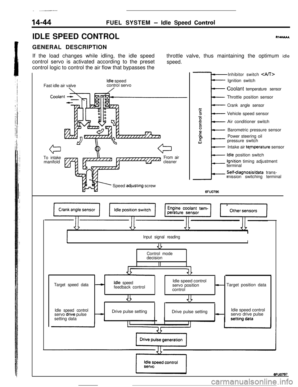
IDLE SPEED CONTROL
RlUU*I,GENERAL DESCRIPTION
If the load changes while idling, the idle speed
control servo is activated according to the preset
control logic to control the air flow that bypasses thethrottle valve, thus maintaining the optimum idle
speed.Fast idle air valve
Idle speed
control servo
Cooiar
To intakemanifoldFrom air
cleanerSpeed
adjustrng screwInhibitor switch
Coolant temperature sensorThrottle position sensor
Crank angle sensorVehicle speed sensor
Air conditioner switch
Barometric pressure sensor
Power steering oil
pressure switch
Intake air te.mperature sensorIdle position switchIgnition timing adjustment
terminalSelfdiagnosisIdata trans-
mission switching terminal
6FUO796
Input signal reading
-3I9Control modedecision
II
41*
Target speed dataIdle speed control---cIdle speed
feedback controlservo position- Target position data
control
Idle speed controlIdle speed control
servo dnve pulse-Drive pulse setting
Drive pulse setting-servo drive pulse
setting data
Page 161 of 391
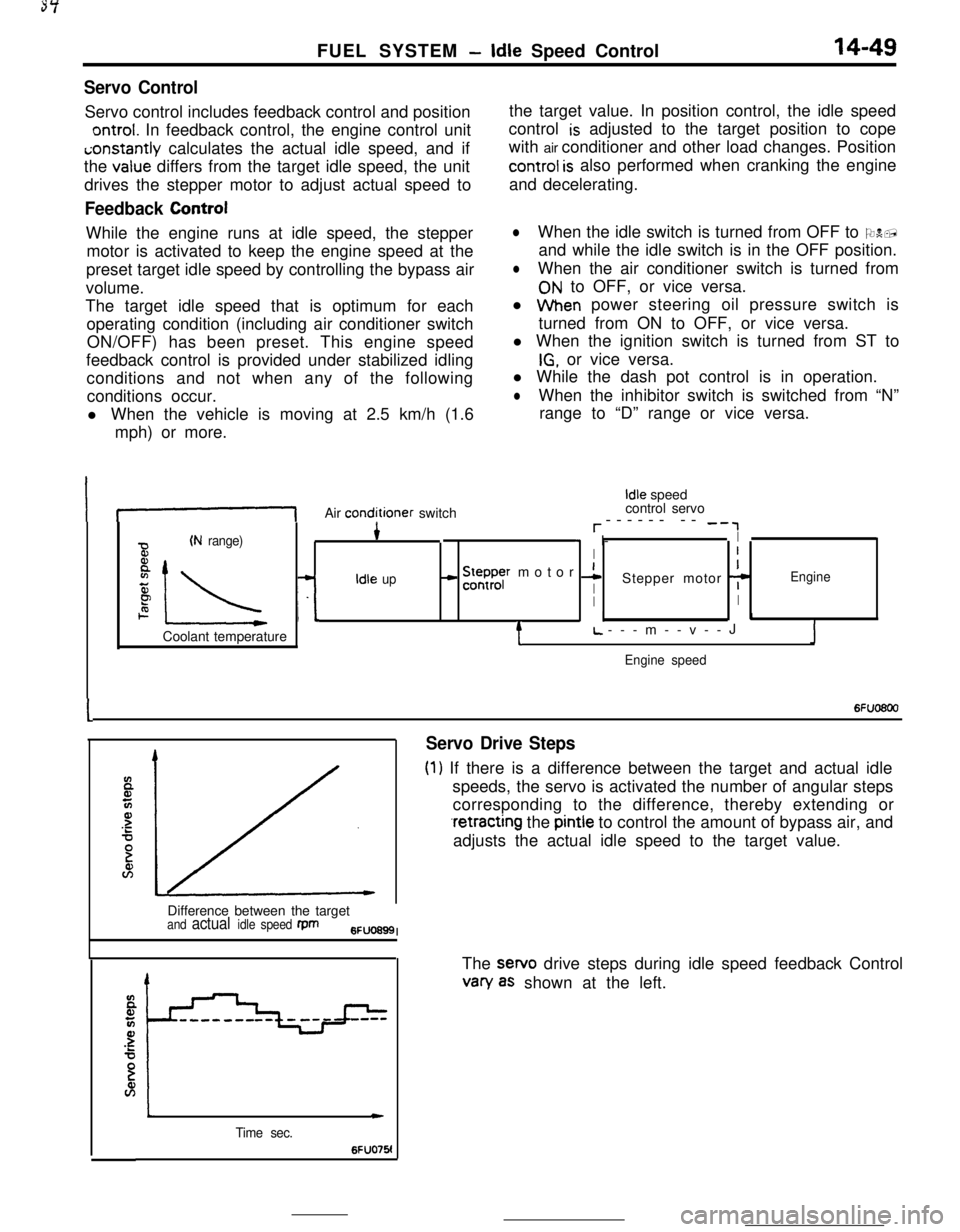
FUEL SYSTEM -Idle Speed Control14-49
Servo ControlServo control includes feedback control and position
ontrol. In feedback control, the engine control uniti;onstantly calculates the actual idle speed, and if
the
value differs from the target idle speed, the unit
drives the stepper motor to adjust actual speed to
Feedback ControlWhile the engine runs at idle speed, the stepper
motor is activated to keep the engine speed at the
preset target idle speed by controlling the bypass air
volume.
The target idle speed that is optimum for each
operating condition (including air conditioner switch
ON/OFF) has been preset. This engine speed
feedback control is provided under stabilized idling
conditions and not when any of the following
conditions occur.
l When the vehicle is moving at 2.5 km/h (1.6
mph) or more.the target value. In position control, the idle speed
control
is adjusted to the target position to cope
with air conditioner and other load changes. Position
control is also performed when cranking the engine
and decelerating.
lWhen the idle switch is turned from OFF to ON,
and while the idle switch is in the OFF position.
lWhen the air conditioner switch is turned from
ON to OFF, or vice versa.
l When power steering oil pressure switch is
turned from ON to OFF, or vice versa.
l When the ignition switch is turned from ST to
IG, or vice versa.
l While the dash pot control is in operation.
lWhen the inhibitor switch is switched from “N”
range to “D” range or vice versa.
If-1Air conditioner switch
Idle speed
control servo
r------ -- -‘,
(N range)4* I-I
BI
8
IL -L
- !5ysr motor 1I
zIdle upIStepper motor 7Engine
PII2. I.1Coolant temperature
tL.---m--v--JJ
Engine speed
I6Fuo6oo
Servo Drive Steps
(1) If there is a difference between the target and actual idle
speeds, the servo is activated the number of angular steps
corresponding to the difference, thereby extending or
.retracting the pintle to control the amount of bypass air, and
adjusts the actual idle speed to the target value.
Difference between the target
and actual idle speed fpm6FUO699I
Time sec.
c
6FUO76!The sewo drive steps during idle speed feedback Control
van/ as shown at the left.
Page 162 of 391
14-50FUEL SYSTEM- Idle Speed Control
SDeed adiustina screwI -Throttle valve
Lw-3O(-22) 0132) 30(86! 601140) 9ofl94)Coolant temperature
“C (OF)6FUO641
E94
72--2--I
Q--.-.-z
3201.000 --4-\-\
5P9.o%IIIaI L-2O(-41 Of3214Of104)801176)Coolant temperature
“C VF)6FU028E
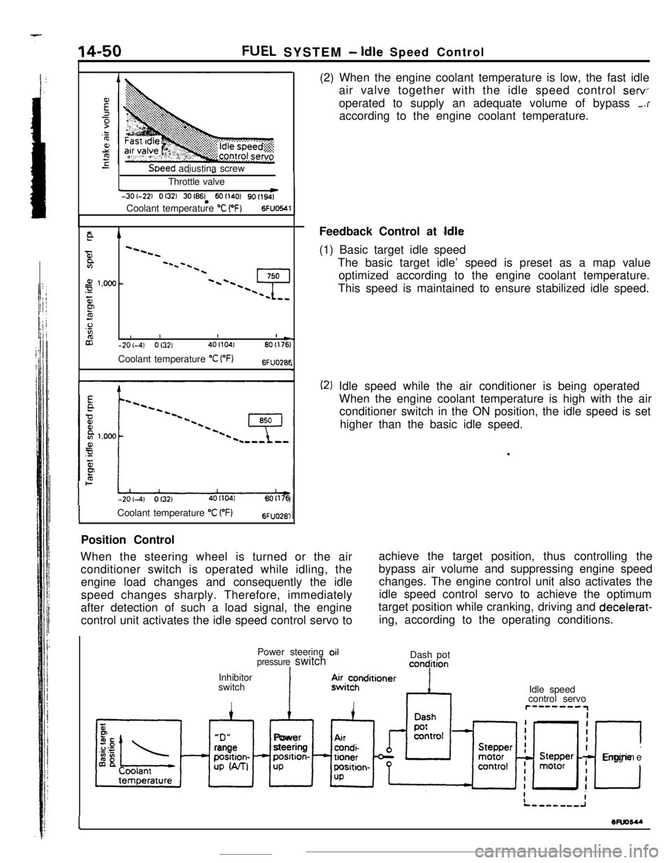
-201-4) Of3214OI104180(176(2) When the engine coolant temperature is low, the fast idle
air valve together with the idle speed control
servoperated to supply an adequate volume of bypass
,.raccording to the engine coolant temperature.
Feedback Control at
Idle(1) Basic target idle speed
The basic target idle’ speed is preset as a map value
optimized according to the engine coolant temperature.
This speed is maintained to ensure stabilized idle speed.
(2) Idle speed while the air conditioner is being operated
When the engine coolant temperature is high with the air
conditioner switch in the ON position, the idle speed is set
higher than the basic idle speed.
,
ICoolant temperature “C VF)6FUO28:Position Control
When the steering wheel is turned or the air
conditioner switch is operated while idling, theachieve the target position, thus controlling the
engine load changes and consequently the idlebypass air volume and suppressing engine speed
changes. The engine control unit also activates the
speed changes sharply. Therefore, immediately
after detection of such a load signal, the engine
control unit activates the idle speed control servo toidle speed control servo to achieve the optimum
target position while cranking, driving and decelerat-
ing, according to the operating conditions.
Power steering oil
pressure switchIInhibitor
switch
IDash pot
concjition“D”
xl
rangeposition-
UP W-U
IAlPower
steeringposition-
UP.4~i~hnditioner
IIdle speed
control servor”--““IiiI
I
c
IEngine
I
I
1wuosu
-