brake fluid MITSUBISHI ECLIPSE 1991 Service Manual
[x] Cancel search | Manufacturer: MITSUBISHI, Model Year: 1991, Model line: ECLIPSE, Model: MITSUBISHI ECLIPSE 1991Pages: 1216, PDF Size: 67.42 MB
Page 17 of 1216
INTRODUCTION AND MASTER TROUBLESHOOTING - Precautions before Sew&e‘37
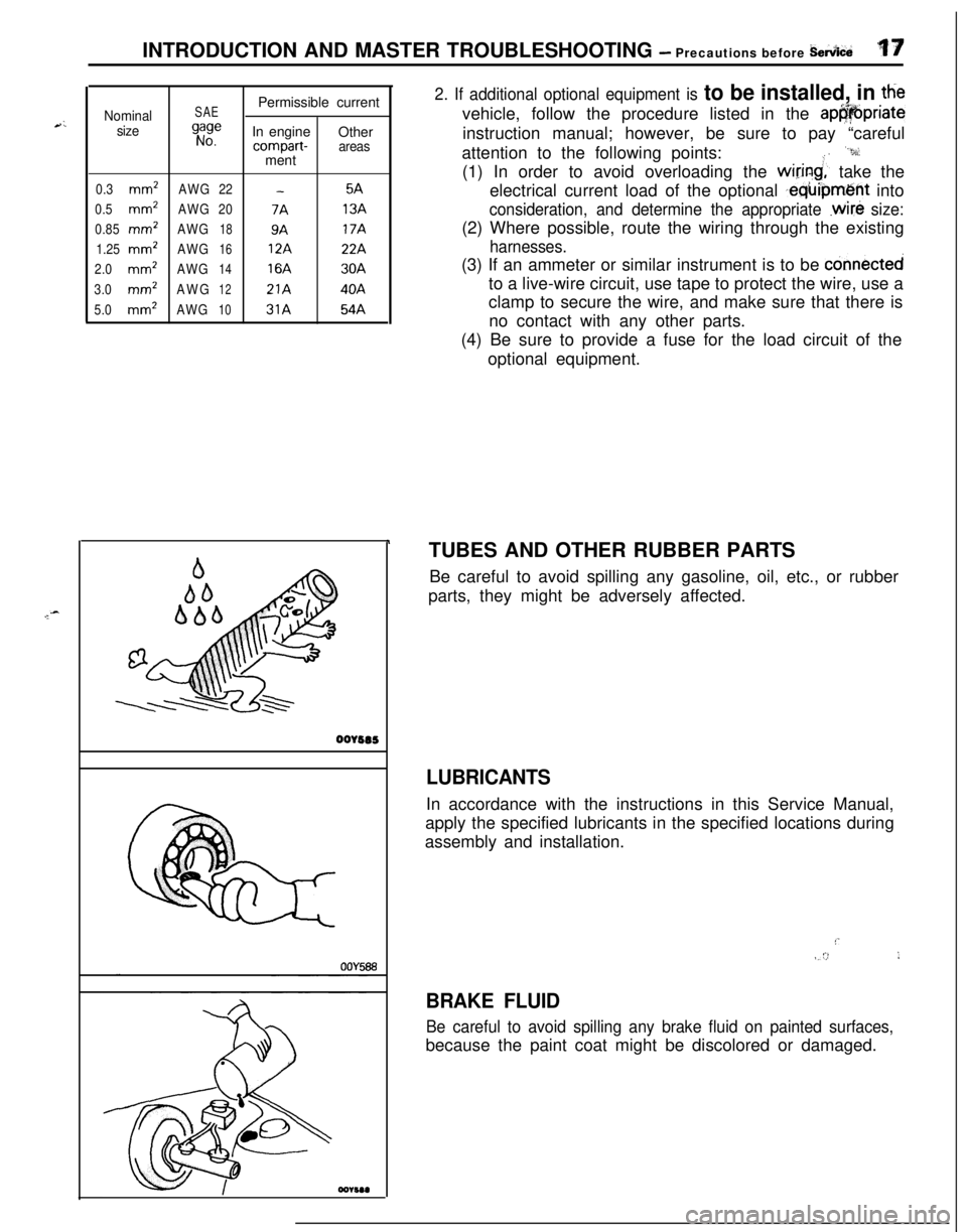
Nominal
sizeSAE
gi:ePermissible current
In engine
Othercompart-areasment
0.3mm2AWG22-5A
0.5
mm2AWG207A13A
0.85
mm’AWG189A17A
1.25
mm2AWG1612A22A
2.0mm2AWG1416A30A
3.0mm’AWG1221A40A
5.0mm2AWG1031A54A
r ‘.
oorsas
2. If additional optional equipment is to be installed, in ttievehicle, follow the procedure listed in the
ap@@priateinstruction manual; however, be sure to pay “careful
attention to the following points:
“9:(1) In order to avoid overloading the
wiring;’ take the
electrical current load of the optional
,equipment into
consideration, and determine the appropriate .wire size:(2) Where possible, route the wiring through the existing
harnesses.(3) If an ammeter or similar instrument is to be
connectedto a live-wire circuit, use tape to protect the wire, use a
clamp to secure the wire, and make sure that there is
no contact with any other parts.
(4) Be sure to provide a fuse for the load circuit of the
optional equipment.
TUBES AND OTHER RUBBER PARTS
Be careful to avoid spilling any gasoline, oil, etc., or rubber
parts, they might be adversely affected.
LUBRICANTSIn accordance with the instructions in this Service Manual,
apply the specified lubricants in the specified locations during
assembly and installation.
!’IV/ :>,I
BRAKE FLUID
Be careful to avoid spilling any brake fluid on painted surfaces,because the paint coat might be discolored or damaged.
Page 31 of 1216
INTRODUCTION AND MASTER TROUBLESH’OOTING .- Master ~pAi&oOti~31POOR FUEL MILEAGE
../, *,, /S./..‘, _I, #_.a,‘.rr?
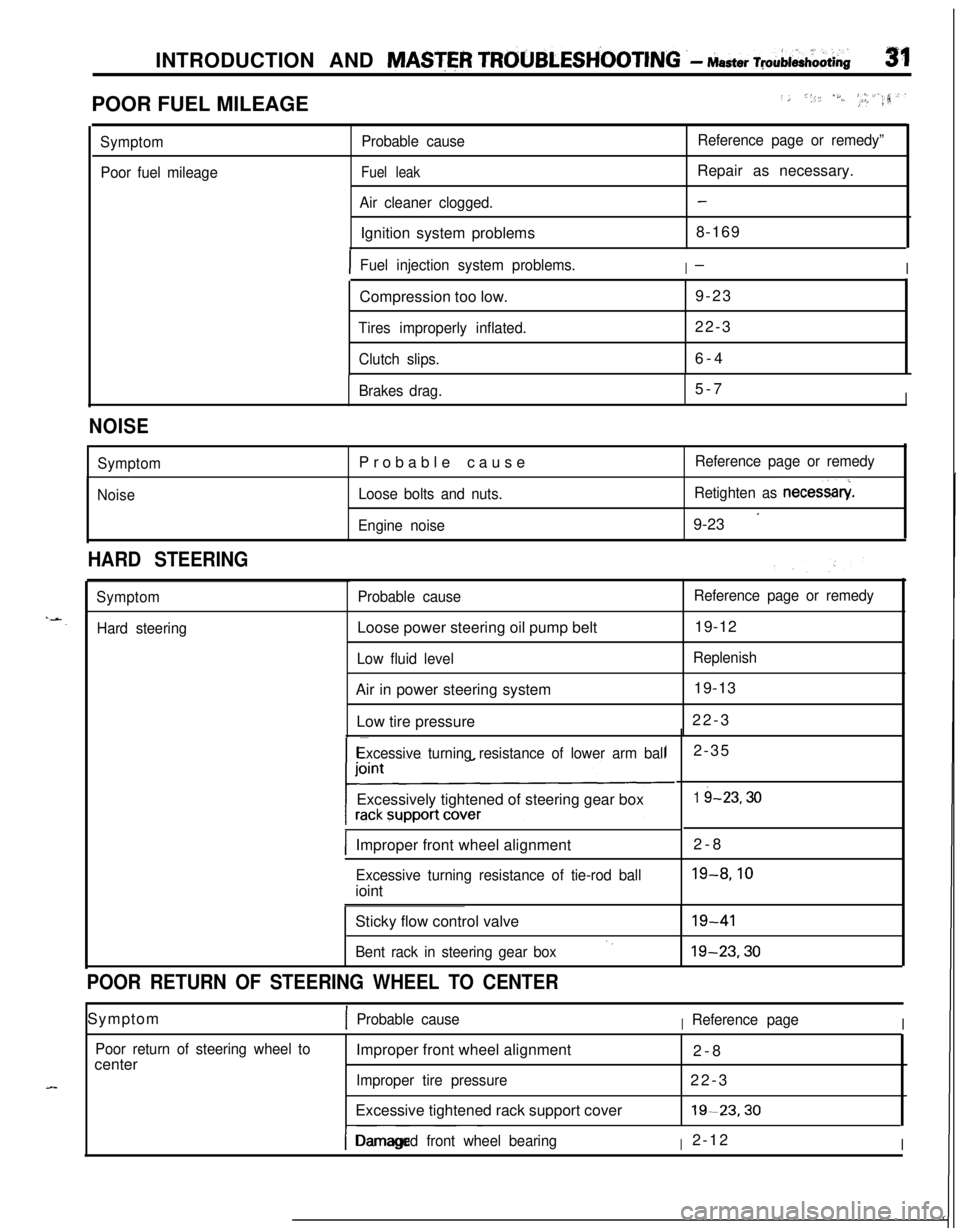
Symptom
Poor fuel mileageProbable cause
Fuel leak
Air cleaner clogged.Ignition system problems
Reference page or remedy”Repair as necessary.
-8-169
IFuel injection system problems.I-ICompression too low.9-23
Tires improperly inflated.22-3
Clutch slips.6-4
Brakes drag.5-7I
NOISE
Symptom
NoiseProbable cause
Loose bolts and nuts.
Engine noiseReference page or remedy
Retighten as necessary
9-23
’
HARD STEERING
Symptom
Hard steeringProbable causeLoose power steering oil pump belt
Low fluid levelAir in power steering system
Low tire pressure
Reference page or remedy19-12
Replenish19-13
22-3
Excessive turning resistance of lower arm ballExcessively tightened of steering gear box
IImproper front wheel alignment2-8
Excessive turning resistance of tie-rod ballioint2-35
1 i-23.30
19-8.10Sticky flow control valve
Bent rack in steering gear box‘.19-4119-23.30
POOR RETURN OF STEERING WHEEL TO CENTERSymptom
1Probable causeIReference pageI
Poor return of steering wheel tocenterImproper front wheel alignment
2-8
Improper tire pressure22-3
Excessive tightened rack support cover19-23.30
I-- ~~~Damaged front wheel bearingI2-12I
Page 37 of 1216
LUBRICATION AND MAINTENANCE - Scheduled MaintenanCe Table. &3
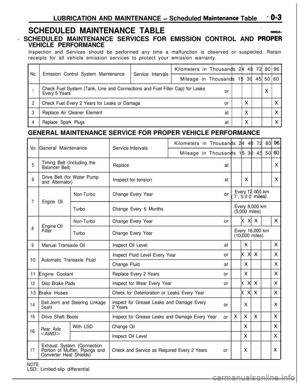
SCHEDULED MAINTENANCE TABLE1
- SCHEDULED MAINTENANCE SERVICES FOR EMISSION CONTROL AND PRO;;
VEHICLE PERFORMANCEInspection and Services should be performed any time a malfunction is observed or suspected. Retain
receipts for all vehicle emission services to protect your emission warranty.
Kilometers in Thousands 24 48 72 80 96
No.Emission Control System Maintenance
Service IntervalsMileage in Thousands 15 30 45 50 60
1Check Fuel System (Tank, Line and Connections and Fuel Filler Cap) for Leaks
Every 5 YearsorX
2Check Fuel Every 2 Years for Leaks or DamageorXX
3Replace Air Cleaner Element
atXX
4Replace Spark Plugs
atXXGENERAL MAINTENANCE SERVICE FOR PROPER VEHICLE PERFORMANCE
Yo. General Maintenance
Service IntervalsKilometers in Thousands 24 48 72 80 9cMileage in Thousands 15 30 45 50
6C
5Timing Belt (Including theBalancer Belt)ReplaceatX
6Drive Belt (for Water Pump
and Alternator)Inspect for tensionatXX.’
Non-TurboChange Every YearEvery 12 000 kmOr (7,500 miles).
7Engine Oil
TurboChange Every 6 MonthsEvery 8,000 km
(5,000 miles)
Non-TurboChange Every Yearor X X XX
8Engine Oil
Filter
TurboChange Every YearEvery 16,000 km
(10,000 miles)
9Manual Transaxle OilInspect Oil LevelatX.X
Inspect Fluid Level Every Yearor X X XX
10Automatic Transaxle Fluid
Change FluidatXX11 Engine Coolant
Replace Every 2 YearsorXX
12Disc Brake PadsInspect for Wear Every Yearor X X XX13 Brake Hoses
Check for Deterioration or Leaks Every YearX X XX
l 4Beiloint and Steering Linkageinspect for Grease Leaks and Damage Every
2 YearsorXX
15Drive Shaft BootsInspect for Grease Leaks and Damage Every Yearor XXXX
Rear Axle
With LSDChange OilXX1 6
Exhaust System (Connection17Portion of Muffler, Pipings andCheck and Service as Required Every 2 Yearsorx -xConverter Heat Shields)
NOTELSD: Limited-slip differential
Page 38 of 1216
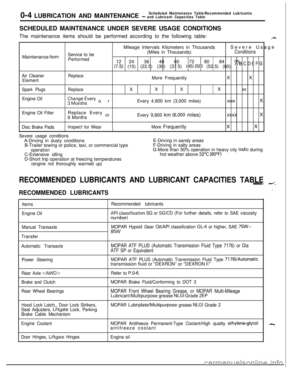
0-4 LUBRICATION AND MAINTENANCEScheduled Maintenance Table/Recommended Lubricants- and Lubricant Capacities TableSCHEDULED MAINTENANCE UNDER SEVERE USAGE CONDITIONS
The maintenance items should be performed according to the following table:
F.Mileage Intervals Kilometers in ThousandsSevere Usage
Service to be(Miles in Thousands)ConditionsMaintenance
Item
Performed24 36 48 60 72 80 84 96
(:,:) (15) (22.5) (30) (37.5) (45) (50) (52.5) (60) * B ’ D E F G
Air CleanerReplaceElementMore FrequentlyXX
Spark PlugsReplace
XXXx xx
Engine Oil$$~~~h~vev orEvery 4,800 km (3,000 miles)xxxx x
Engine Oil FilterReplace Every or6 MonthsEvery 9,600 km (6,000 miles)xxxx x
Disc Brake PadsInspect for WearMore FrequentlyXX
Severe usage conditionsA-Driving in dusty conditionsE-Driving in sandy areas
B-Trailer towing or police, taxi, or commercial typeF-Driving in salty areas
operationG-More than 50% operation in heavy city trafic during
C-Extensive idlinghot weather above 32°C (90°F)D-Short trip operation at freezing temperatures
(engine not thoroughly warmed up)
RECOMMENDED LUBRICANTS AND LUBRICANT CAPACITIES TABLENOONA- --z.
RECOMMENDED LUBRICANTS
Items
Engine Oil
Manual Transaxle
TransferRecommended lubricantskF&cesisification
SG or SG/CD (For further details, refer to SAE viscosity
MOPAR Hypoid Gear
Oil/API classification GL4 or higher, SAE 75W-85W
Automatic TransaxleMOPAR ATF PLUS (Automatic Transmission Fluid Type 7176) or Dia
ATF SP or Equivalent
Power SteeringMOPAR ATF PLUS (Automatic Transmission Fluid Type 7176VAutomatictransmission fluid or “DEXRON” or “DEXRON II”
Rear Axle
Brake and Clutch
Rear Wheel BearingsRefer to
P.O-6.
MOPAR Brake Fluid/Conforming to DOT 3
MOPAR Front Wheel Bearing Grease, or MOPAR Multi-MileageLubricant/Multipurpose grease NLGI Grade 2EP
Hood Lock Latch,, Door Lock Strikers,
Seat Adjusters, Lrftgate Lock, Parking
Brake Cable MechanismMOPAR Lubriplate/Multipurpose grease NLGI Grade 2
Engine CoolantMOPAR Antifreeze Permanent-Type Coolant/High quality
ethylene-glycolantifreeze coolant
Door Hinges, Liftgate Hinges
Engine oil
/
N
Page 46 of 1216
LUBRICATION AND MAINTENANCE - Maintenance Service
L-4GoodOOA0051C9FW1014K512(9) Supply 4 liters (8.5 pints) of specified ATF into case
through dipstick hole. [Total quantity of ATF required is
6.1 liters (12.9 pints).
Actually however, approx. 4.5 liters (9.5 pints) of fluid
can be replaced because rest of fluid remains in torque
converter.]Specified fluid: MOPAR ATF PLUS (Automatic
Transmission Fluid Type 7176) or
Dia ATF SP or Equivalent
(10)Start engine and allow to idle for at least two minutes.
Then, with parking brake on, move selector lever
momentarily to each position, ending in “N” Neutral
position.
(1 l)Add sufficient ATF to bring fluid level to lower mark.
Recheck fluid level after transaxle is at normal operating
temperature.
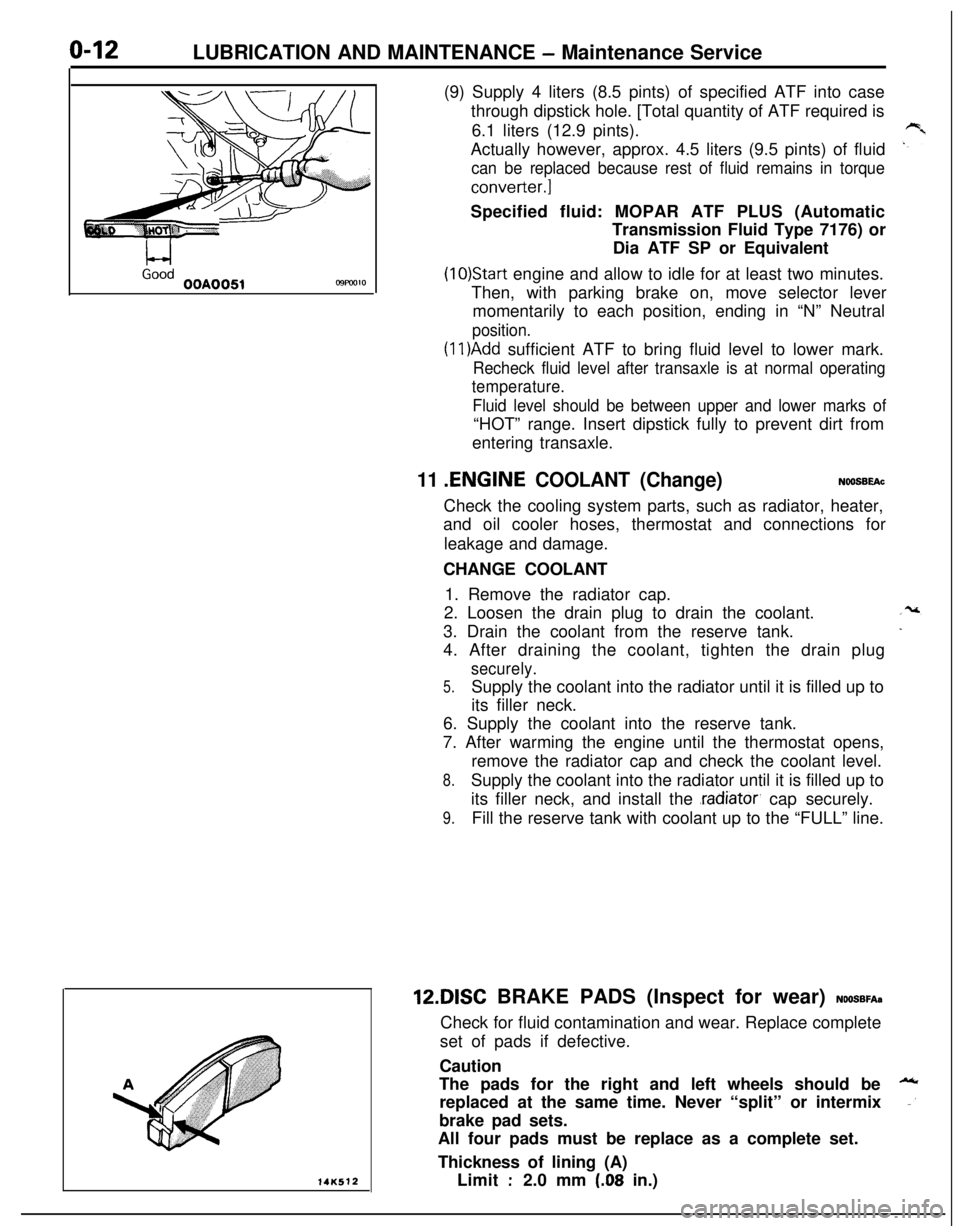
Fluid level should be between upper and lower marks of“HOT” range. Insert dipstick fully to prevent dirt from
entering transaxle.
11 .ENGINE COOLANT (Change)NOOSBEAcCheck the cooling system parts, such as radiator, heater,
and oil cooler hoses, thermostat and connections for
leakage and damage.
CHANGE COOLANT
1. Remove the radiator cap.
2. Loosen the drain plug to drain the coolant.
3. Drain the coolant from the reserve tank.
4. After draining the coolant, tighten the drain plug
securely.
5.Supply the coolant into the radiator until it is filled up to
its filler neck.
6. Supply the coolant into the reserve tank.
7. After warming the engine until the thermostat opens,
remove the radiator cap and check the coolant level.
8.Supply the coolant into the radiator until it is filled up to
its filler neck, and install the
.radiator, cap securely.
9.Fill the reserve tank with coolant up to the “FULL” line.12DISC BRAKE PADS (Inspect for wear)
NOOSBFA~Check for fluid contamination and wear. Replace complete
set of pads if defective.
Caution
The pads for the right and left wheels should be
replaced at the same time. Never “split” or intermix
brake pad sets.
All four pads must be replace as a complete set.
Thickness of lining (A)
Limit
:2.0 mm (.08 in.)
Page 141 of 1216
BRAKES
SERVICE AND PARKING
CONTENTS
ANTI-LOCK BRAKING SYSTEM
TROUBLESHOOTING
......................................
9
BRAKEBOOSTER...........................................
60BRAKE LINE
....................................................
62
BRAKE PEDAL.................................................
53ELECTRONIC CONTROL UNIT
- FRONT DISC BRAKE......................................
65G-SENSOR
HYDRAULIC UNIT
77
MASTERCYLINDER
........................................56
PARKING BRAKES
..........................................88
REAR
DISC BRAKE.........................................70SERVICE ADJUSTMENT PROCEDURES..
.....41
ABSPowerRelayCheck.............................52
Bleeding........................................................
45Brake Booster Operating
Inspection...........43
BrakeFluidLevelSensor Check.................
42Brake Pedal Inspection and Adjustment
.....41Check Valve
OperationCheck.....................
44
FlatBattery
Remedy....................................52
FrontBrakeDiscRun-out Check................47Front Brake Disc Run-out Correction
..........48Front Brake
Disc Thickness Check
.............47Front Disc Brake Pad Check and
Replacement.................................................46
Parking
BrakeLever Stroke Check.............42
Parking
BrakeSwitchCheck.......................43
Proportioning
ValveFunctionTest...............44Rear Brake
DiscRun-out Check.................50Rear Brake Disc Run-out Correction
...........50Rear Brake
Disc Thickness
Check..............49Rear Disc Brake Pad Check and
Replacement.................................................48Observation of Wheel Speed Sensor
Output Voltage Variations
ABS>..................................51
SPECIAL TOOLS.............................................6
SPECIFICATIONS.............................................
2General Specifications
..................................2
Lubricants
......................................................5
Service
Specifications...................................4
Torque
Specifications...................................4
TROUBLESHOOTING......................................7WHEEL SPEED SENSOR
_ CAUTION
When servicing brake assemblies or components, do not create dust by sanding, grinding or by cleaning
brake parts with a dry brush or with compressed air. A WATER DAMPENED CLOTH SHOULD BE USED.
Many brake components contain asbestos fibers which can become air-borne if dust is created duringservice operations. Breathing dust which contains asbestos fibers can cause serious bodily harm.
Page 145 of 1216
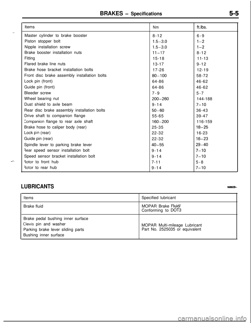
BRAKES - Specifications5-5Items
Nmftlbs.Master cylinder to brake booster
8-126-9
Piston stopper bolt
1.5-3.0l-2Nipple installation screw
1.5-3.0l-2Brake booster installation nuts
11-178-12
Fitting15-1811-13
Flared brake line nuts
13-179-12
Brake hose bracket installation bolts
17-2612-19
Front disc brake assembly installation bolts
80-10058-72
Lock pin (front)
64-8646-62
Guide pin (front)
64-8646-62
Bleeder screw
7-95-7
Wheel bearing nut
200-260144-188
Dust shield to axle beam
9-14
7-10Rear disc brake assembly installation bolts
50-6036-43
Drive shaft to companion flange
55-6539-47
companion flange to rear axle shaft160-200116-159
Brake hose to caliper body (rear)
25-35
18-25Lock
pin (rear)
22-3216-23
Guide pin (rear)
22-32
16-23Spindle lever to parking brake lever
40-5529-40
3ear speed sensor installation bolt
9-147-10Speed sensor bracket installation bolt
9-14
7-10
3otor to front hub
7-115-8
3otor to rear hub
9-147-10
LUBRICANTSNO5CP-
ItemsBrake fluidSpecified lubricant
MOPAR Brake
Fluid/Conforming to
DOT3Brake pedal bushing inner surface
Clevis pin and washer
Parking brake lever sliding parts
Bushing inner surfaceMOPAR Multi-mileage Lubricant
Part No. 2525035 or equivalent
Page 181 of 1216
BRAKES - Service Adjustment Procedures5-47switch
switch
v14F516
Idown ,./
F14517
F14518
F14519
SERVICE ADJUSTMENT PROCEDURES
BRAKE PEDAL INSPECTION AND ADJUSTM&g
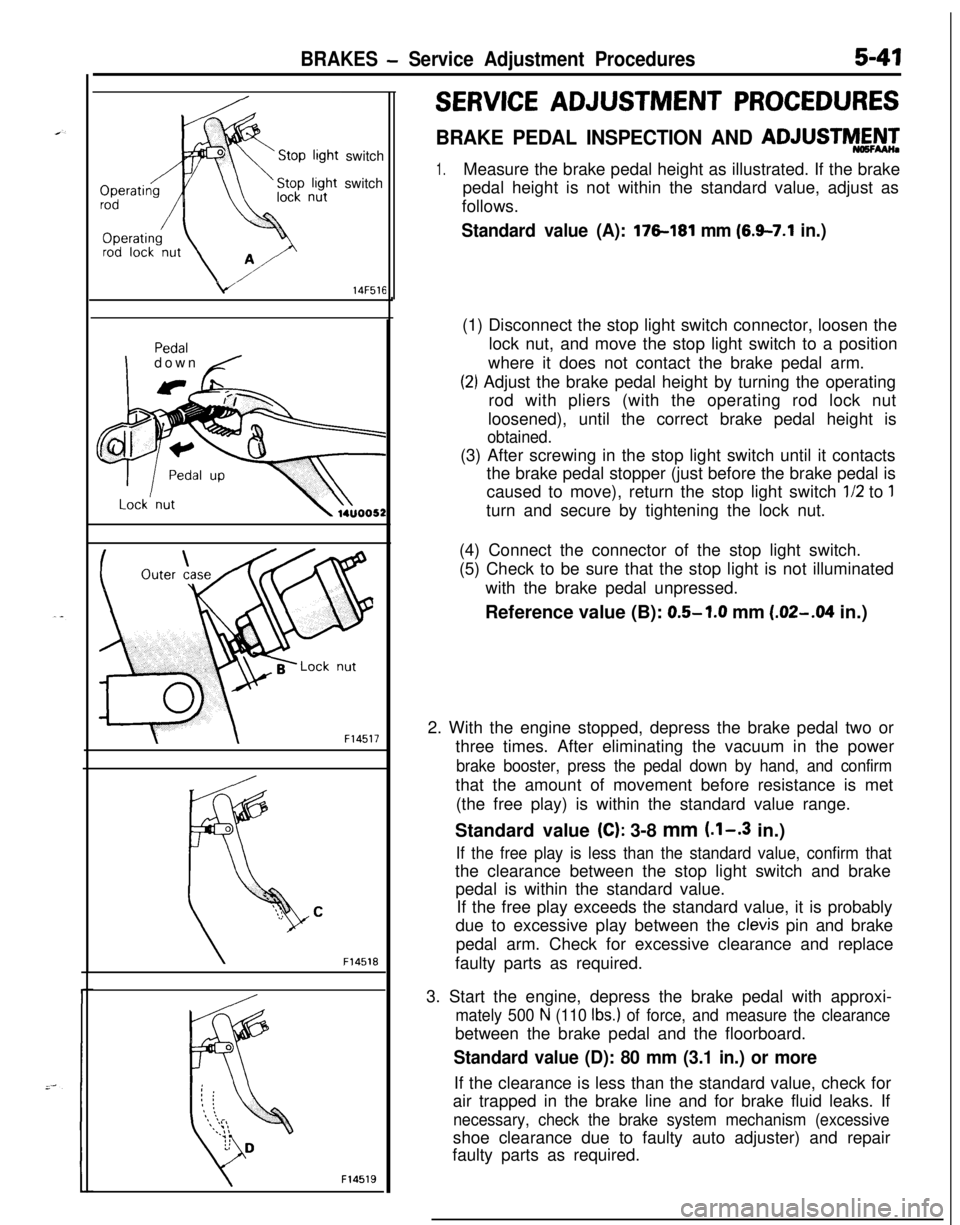
1.Measure the brake pedal height as illustrated. If the brake
pedal height is not within the standard value, adjust as
follows.
Standard value (A): 176181 mm (6.9-7.1 in.)(1) Disconnect the stop light switch connector, loosen the
lock nut, and move the stop light switch to a position
where it does not contact the brake pedal arm.
(2) Adjust the brake pedal height by turning the operating
rod with pliers (with the operating rod lock nut
loosened), until the correct brake pedal height is
obtained.(3) After screwing in the stop light switch until it contacts
the brake pedal stopper (just before the brake pedal is
caused to move), return the stop light switch
l/2 to 1turn and secure by tightening the lock nut.
(4) Connect the connector of the stop light switch.
(5) Check to be sure that the stop light is not illuminated
with the brake pedal unpressed.
Reference value (B): 0.5-1.0 mm
(.02-M in.)
2. With the engine stopped, depress the brake pedal two or
three times. After eliminating the vacuum in the power
brake booster, press the pedal down by hand, and confirmthat the amount of movement before resistance is met
(the free play) is within the standard value range.
Standard value
(C): 3-8 mm (.l-.3 in.)
If the free play is less than the standard value, confirm thatthe clearance between the stop light switch and brake
pedal is within the standard value.
If the free play exceeds the standard value, it is probably
due to excessive play between the
clevis pin and brake
pedal arm. Check for excessive clearance and replace
faulty parts as required.
3. Start the engine, depress the brake pedal with approxi-
mately 500 N (110 Ibs.) of force, and measure the clearancebetween the brake pedal and the floorboard.
Standard value (D): 80 mm (3.1 in.) or moreIf the clearance is less than the standard value, check for
air trapped in the brake line and for brake fluid leaks. If
necessary, check the brake system mechanism (excessiveshoe clearance due to faulty auto adjuster) and repair
faulty parts as required.
Page 182 of 1216
5-42BRAKES - Service Adjustment Procedures
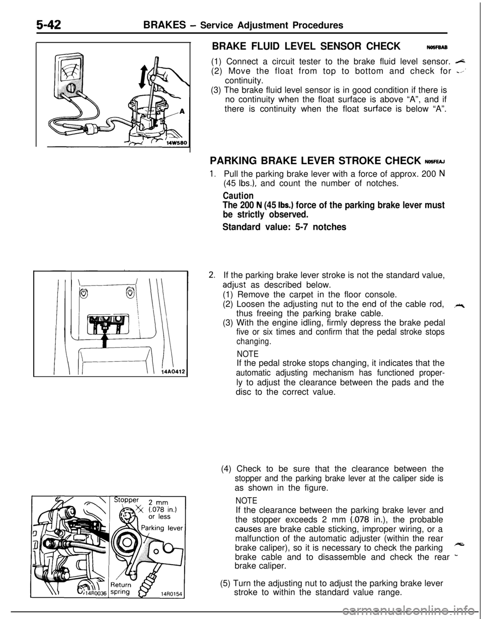
BRAKE FLUID LEVEL SENSOR CHECKNO5FBAB(1) Connect a circuit tester to the brake fluid level sensor.
4(2) Move the float from top to bottom and check for
.-,’continuity.
(3) The brake fluid level sensor is in good condition if there is
no continuity when the float surface is above “A”, and if
there is continuity when the float
surface is below “A”.
PARKING BRAKE LEVER STROKE CHECK NWFEAJ
1.Pull the parking brake lever with a force of approx. 200 N(45
Ibs.), and count the number of notches.
Caution
The 200 N (45 Ibs.) force of the parking brake lever must
be strictly observed.
Standard value: 5-7 notches
2.If the parking brake lever stroke is not the standard value,
adjust as described below.
(1) Remove the carpet in the floor console.
(2) Loosen the adjusting nut to the end of the cable rod,
fithus freeing the parking brake cable.
(3) With the engine idling, firmly depress the brake pedal
five or six times and confirm that the pedal stroke stops
changing.
NOTEIf the pedal stroke stops changing, it indicates that the
automatic adjusting mechanism has functioned proper-ly to adjust the clearance between the pads and the
disc to the correct value.
(4) Check to be sure that the clearance between the
stopper and the parking brake lever at the caliper side isas shown in the figure.
NOTEIf the clearance between the parking brake lever and
the stopper exceeds 2 mm
(078 in.), the probable
causes are brake cable sticking, improper wiring, or a
malfunction of the automatic adjuster (within the rear
brake caliper), so it is necessary to check the parking
-brake cable and to disassemble and check the rear
-brake caliper.
(5) Turn the adjusting nut to adjust the parking brake lever
stroke to within the standard value range.
Page 184 of 1216

BRAKES - Service Adjustment Procedures
WA041 7
Pressure
gaugePressure
PropG-tioning valve t4Lmt
,’
,Sdit point
outputpressure
Input pressure
14uoo55CHECK VALVE OPERATION CHECK
NOSFNAJ
When checking the check valve, keep the check valve fit in thevacuum hose.
1. Remove the vacuum hose.
Caution
The check valve is press-fit inside the vacuum hose and
do not remove the check valve from the vacuum hose.
2.Check the operation of the check valve by using a vacuum
pump.Vacuum pump connection Accept/reject criteria
Connection at the brake A negative pressure (vacuum) is
booster side
@Icreated and held.
Connection at the intake
manifold side
@A negative pressure (vacuum) is notcreated.
Caution
If the check valve is defective, replace it as an assembly
unit together with the vacuum hose.PROPORTIONING VALVE FUNCTION TEST
NOSFKAJ
1.Connect two pressure gauges, one each to the input side
and output side of the proportioning valve, as shown.
2. Air bleed the brake line and the pressure gauge.
3. While gradually depressing the brake pedal, make the
following measurements and check to be sure that the
measured values are within the allowable range.
(1) Output pressure begins to drop relative to input
pressure (split point).
Standard value:
MPa (561-633 psi)
MPa (491-561 psi)
(2) Output fluid pressure when input fluid pressure are as
follows.
Standard value:
tFVVD>5.15-5.65 MPa (732-804 psi)
[at 8.2
MPa (1,163 psi)]
MPa (661-732 psi)
[at 7.7
MPa (1,095 psi)],
(3) Output pressure difference between left and right
brake lines
Limit: 0.4
MPa (57 psi)
4. If the measured pressures are not within the
permissibleranges, replace the proportioning valve.