brake fluid MITSUBISHI ECLIPSE 1991 Owner's Manual
[x] Cancel search | Manufacturer: MITSUBISHI, Model Year: 1991, Model line: ECLIPSE, Model: MITSUBISHI ECLIPSE 1991Pages: 1216, PDF Size: 67.42 MB
Page 210 of 1216
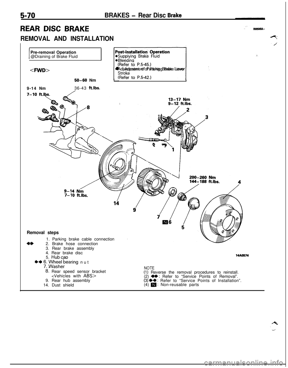
5-70
REAR DISC BRAKE
BRAKES -’ Rear Disc Brake
REMOVAL AND INSTALLATION
IPre-removal Operation
@Draining of Brake Fluid
~1 ,.
l Adjustment of Parking Brake Lever
1.150-60Nm
9-14
Nm36-43ft.lbs.
7-10ft.lbs./
7- 10ft.lbs.
Removal steps
4*1. Parking brake cable connection
2. Brake hose connection
3. Rear brake assembly
4. Rear brake disc
5.
Hubcab
+4 76. ME;AFearing nut
8: Rear speed sensor bracket
14. Dust shield
NOTE(1) Reverse the removal procedures to reinstall.
(2) +* : Refer to “Service Points of Removal”.(3) ** : Refer to “Service Points of Installation”.
(4) m : Non-reusable parts
MAO574
Page 211 of 1216
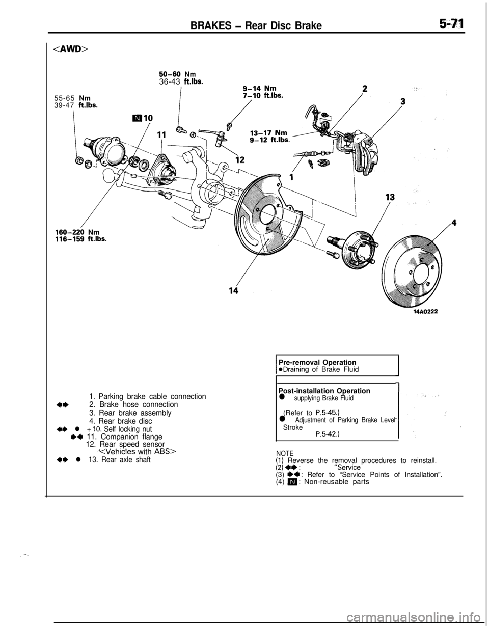
BRAKES - Rear Disc Brake59q!l
50-60Nm36-43ft.lbs.9-14Nm55-65Nm
39-47
klbs.
/160-220 Nm116-159 ft.lbs.14A0222
1. Parking brake cable connection
4*2. Brake hose connection
3. Rear brake assembly
4. Rear brake disc
+e l + IO. Self locking nutr)+ 11. Companion flange
12. Rear speed sensor
KVehicles with ABS>+e l 13. Rear axle shaftPre-removal Operation
@Draining of Brake Fluid
Post-installation Operation
l supplying Brake Fluid(Refer to
P.5-45.)l Adjustment of Parking Brake LevelStrokeP.5-42.)
NOTE
(1) Reverse the removal procedures to reinstall.(2) +e:“Service
(3) I)+ : Refer to “Service Points of Installation”.
(4) m : Non-reusable parts
Page 214 of 1216

5-74BRAKES -Rear Disc Brake
1410062
14R0050
14UOO72
SERVICE POINTS OF DISASSEMBLYNO5NBAEWhen disassembling the rear disc brakes, disassemble both
sides (left and right) as a set.
3. REMOVAL OF SUPPORT MOUNTINGWith the lock pin removed, pull the support mounting off
from the caliper body.
9. DISASSEMBLY OF PISTON ASSEMBLYUse the special tool to twist the piston out of the caliper
body.
10. DISASSEMBLY OF PISTON SEAL
(1) Remove piston seal with finger tip.
Caution
Do not use flat tip (-) screwdriver or other tool to
prevent damage to inner cylinder.(2) Clean piston surface and inner cylinder with
trichloro-ethylene, alcohol or specified brake fluid.
Specified brake fluid: MOPAR Brake Fluid/
Conforming to DOT3
11. DISASSEMBLY OF SNAP RINGWhile using a 19 mm
(75 in.) diameter steel pipe to press
the spring case into the caliper body, use the snap ring
pliers to remove the snap ring from the caliper body.
INSPECTIONN65NCAAa
e Check the connecting link and the spindle for wear or
damage.l
l Check the spindle lever shaft for rust.
l
l Check the piston for rust.
Check the piston seal for wear or deterioration.
l
piston
PAD WEAR CHECK(1) Measure the thickness of the pad at the thinnest place.
(.08(2) If the pad assemblies are worn beyond the limit, replace
them.
Page 217 of 1216
BRAKES - Hydraulic Unit
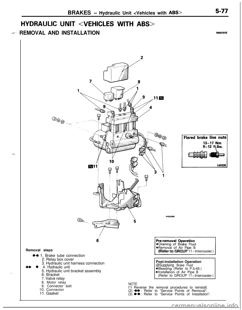
HYDRAULIC UNIT
--. REMOVAL AND INSTALLATION
6Removal steps
I)+ 1. Brake tube connection
2. Relay box cover
3. Hydraulic unit harness connection
~~ l 4. Hydraulic unit5. Hydraulic unit bracket assembly
6. Bracket
7. Valve relay
1(Refer to GROUP
II-Intercooler.)Post-installation Operation
@Supplying Brake FluidaBleeding (Refer to P.5-45.)@Installation of Air Pipe B(Refer to GROUP II-Intercooler.)8. Motor relay
9. Connector bolt
10. Connector
11. Gasket
NOTE(1) Reverse the removal procedures to reinstall.
(2) +e : Refer to “Service Points of Removal”.
(3) e+ : Refer to “Service Points of Installation”.
Page 233 of 1216
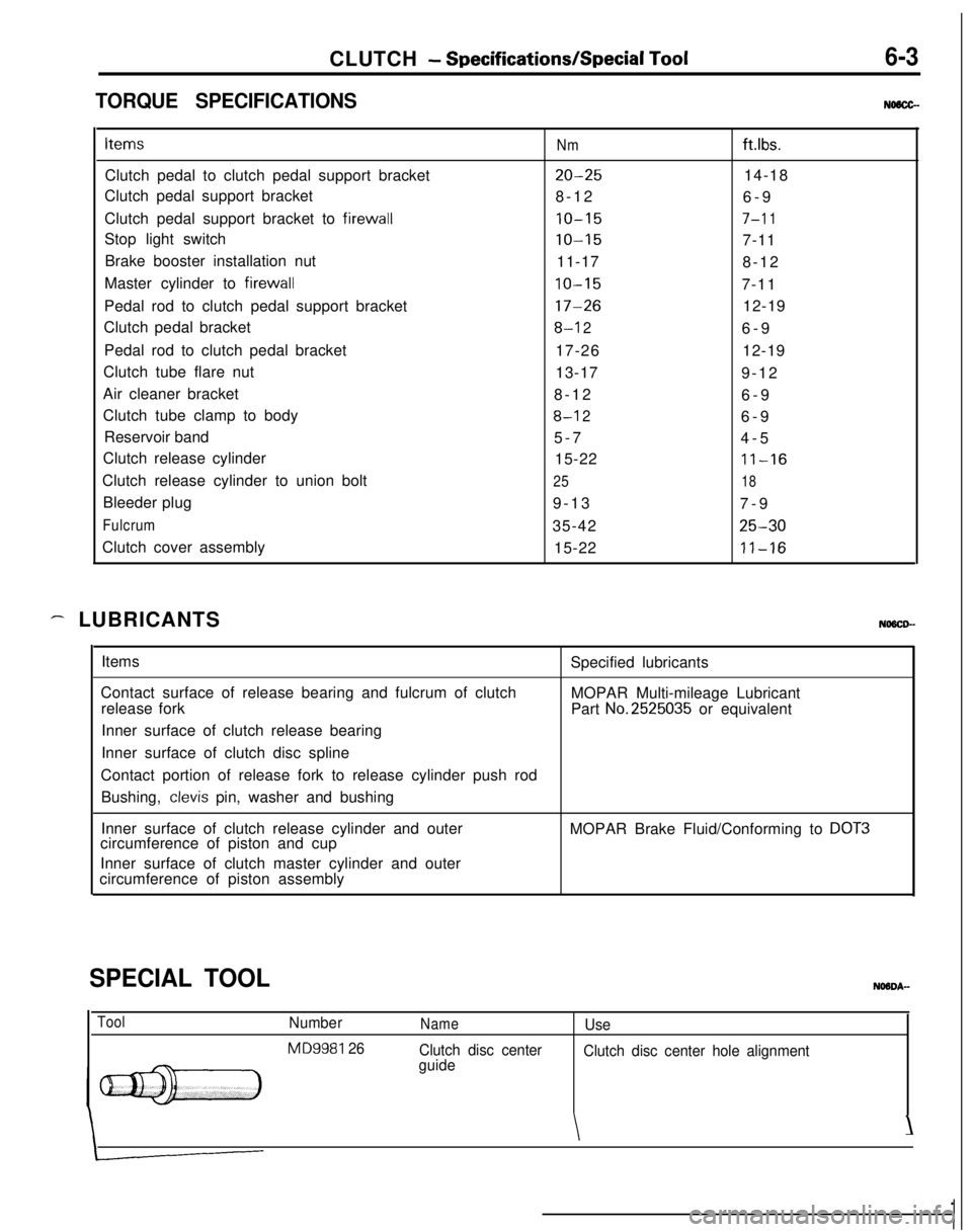
CLUTCH - Specifications/Special Tool6-3
TORQUE SPECIFICATIONSNMCC-Items
Nmftlbs.Clutch pedal to clutch pedal support bracket
20-2514-18
Clutch pedal support bracket
8-12
6-9
Clutch pedal support bracket to firewall
10-157-l 1Stop light switch
10-157-11
Brake booster installation nut
11-17
8-12
Master cylinder to firewall
10-157-11
Pedal rod to clutch pedal support bracket
17-2612-19
Clutch pedal bracket
8-l 26-9
Pedal rod to clutch pedal bracket
17-2612-19
Clutch tube flare nut
13-17
9-12
Air cleaner bracket
8-12
6-9
Clutch tube clamp to body
8-l 26-9
Reservoir band
5-7
4-5
Clutch release cylinder
15-22
11-16Clutch release cylinder to union bolt
2518Bleeder plug
9-13
7-9
Fulcrum35-4225-30Clutch cover assembly
15-22
11-16
- LUBRICANTSNOSCD-Items
Contact surface of release bearing and fulcrum of clutch
release fork
Inner surface of clutch release bearing
Inner surface of clutch disc splineSpecified lubricants
MOPAR Multi-mileage Lubricant
Part
No.2525035 or equivalent
Contact portion of release fork to release cylinder push rod
Bushing,
clevis pin, washer and bushing
Inner surface of clutch release cylinder and outer
circumference of piston and cupMOPAR Brake Fluid/Conforming to
DOT3Inner surface of clutch master cylinder and outer
circumference of piston assembly
SPECIAL TOOL
ToolNumber
MD9981 26
NameUse
Clutch disc center
guideClutch disc center hole alignment
\\
Page 236 of 1216
6-6CLUTCH - Service Adjustment Procedures
5.If the clutch pedal free play and the distance between the
clutch pedal and the firewall when the clutch is disengageddo not agree with the standard values, it is probably the
A
result of either air in the hydraulic system or a faulty master2
cylinder or clutch. Bleed the air, or disassemble and inspectthe master cylinder or clutch.
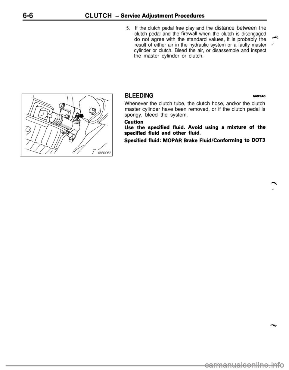
BLEEDINGWhenever the clutch tube, the clutch hose, and/or the clutch
master cylinder have been removed, or if the clutch pedal is
spongy, bleed the system.
Caution
Use the specified fluid. Avoid using a mixture of the
specified fluid and other fluid.
Specified fluid: MOPAR Brake Fluid/Conforming to DOT3
Page 242 of 1216
6-12CLUTCH - Clutch Master CylinderResew&r
bandk
oaA0058
08Y517
Grease
SERVICE POINTS OF REASSEMBLYNaaNciAN
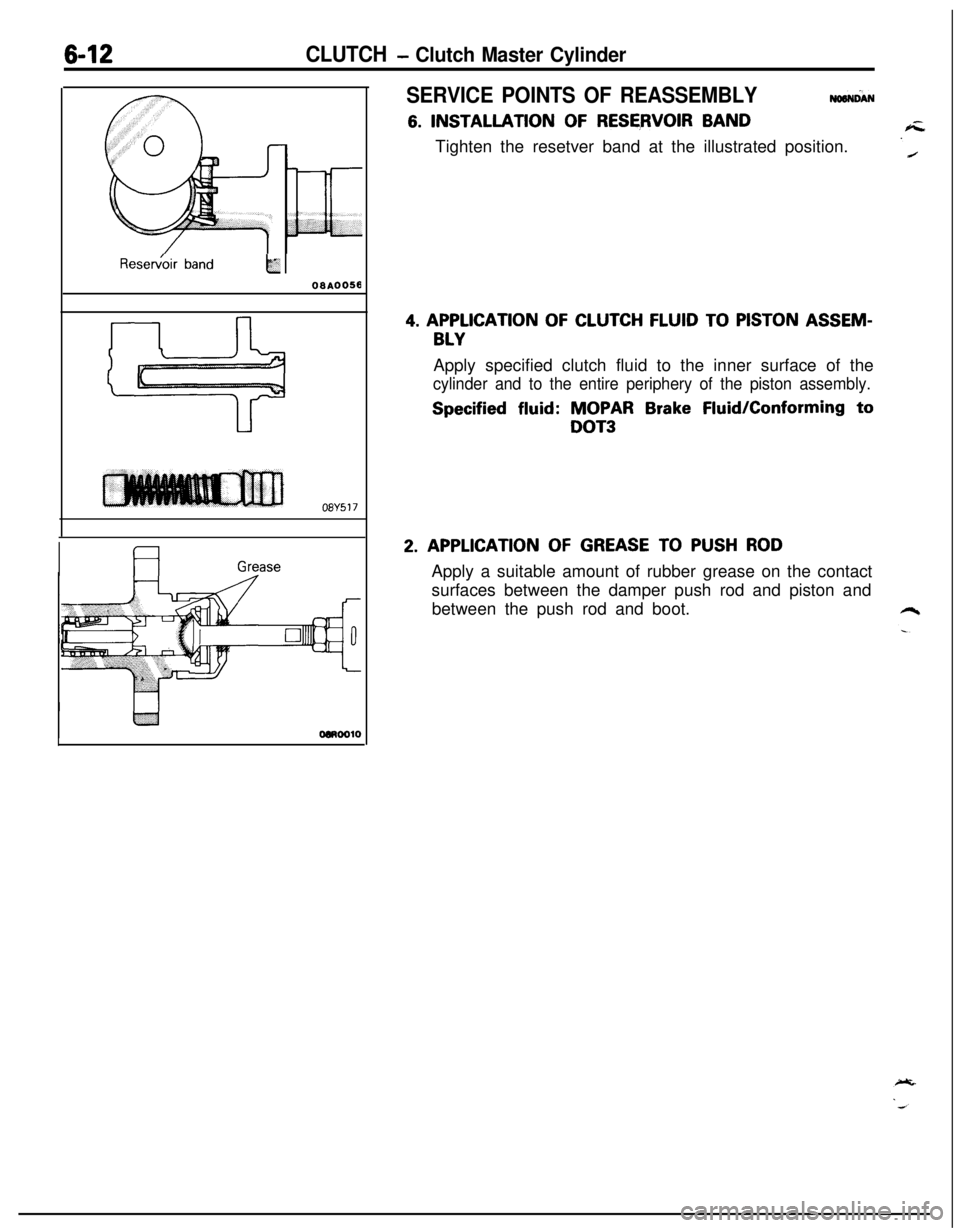
6. INSTALLATION OF RESERVOIR BAND
Tighten the resetver band at the illustrated position.
4. APPLICATION OF CLUTCH FLUID TO PISTON ASSEM-
BLYApply specified clutch fluid to the inner surface of the
cylinder and to the entire periphery of the piston assembly.
Specified fluid: MOPAR Brake Fluid/Conforming to
DOT3
2. APPLICATION OF GREASE TO PUSH RODApply a suitable amount of rubber grease on the contact
surfaces between the damper push rod and piston and
between the push rod and boot.
Page 244 of 1216
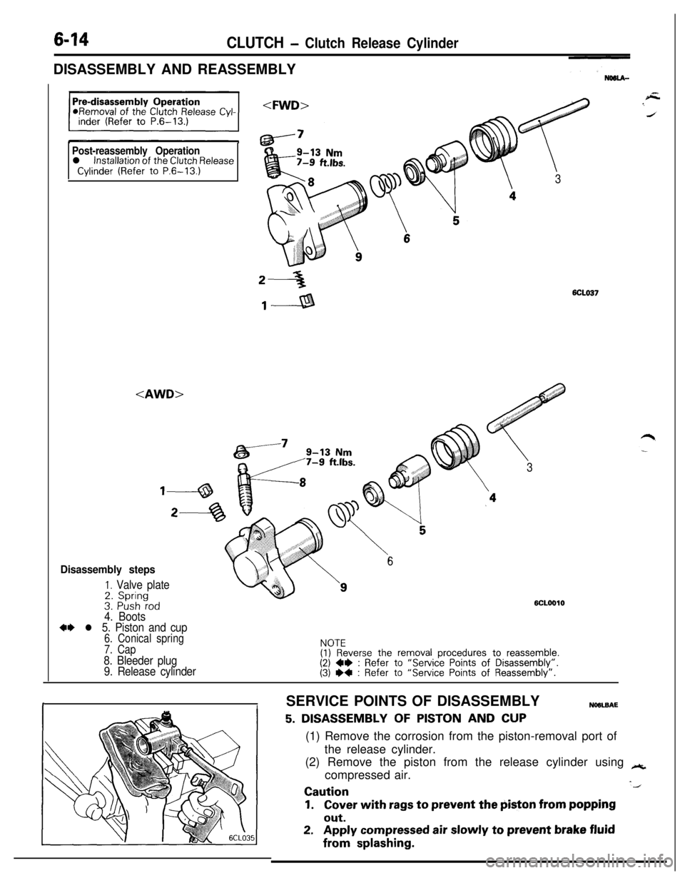
6-14CLUTCH - Clutch Release CylinderDISASSEMBLY AND REASSEMBLY
Post-reassembly Operationl installation of the Clutch ReleaseCylinder (Refer to P.6-13.)
,, #,,“”
7
3
2-36CLO37
,---a
#,J,,, ‘::.”/,,,,d$’ ’.,:..a
<
/ : i 01‘, ., 1
3
Disassembly steps
I. Valve plate2. Spring
6
3. Push rod4. Boots
6CLOOlO
*+ l 5. Piston and cup6. Conical spring
7. Cap
8. Bleeder plug
9. Release cylinder
NOTE(1) Reverse the removal procedures to reassemble.(2) W : Refer to “Service Points of Disassembly”.(3) I)4 : Refer to “Service Points of Reassembly”.
rISERVICE POINTS OF DISASSEMBLYNOOLBAE
5. DISASSEMBLY OF PISTON AND CUP(1) Remove the corrosion from the piston-removal port of
the release cylinder.
(2) Remove the piston from the release cylinder using
++,compressed air.
-JCaution
1.Cover with rags to prevent the piston from popping
out.
2.Apply compressed air slowly to prevent brake fluidfrom
splashing.
Page 245 of 1216
.-CLUTCH - Clutch Release Cvlinder6-15
\
Piston
@*
CUP6CLOOO3DCLOOE
,
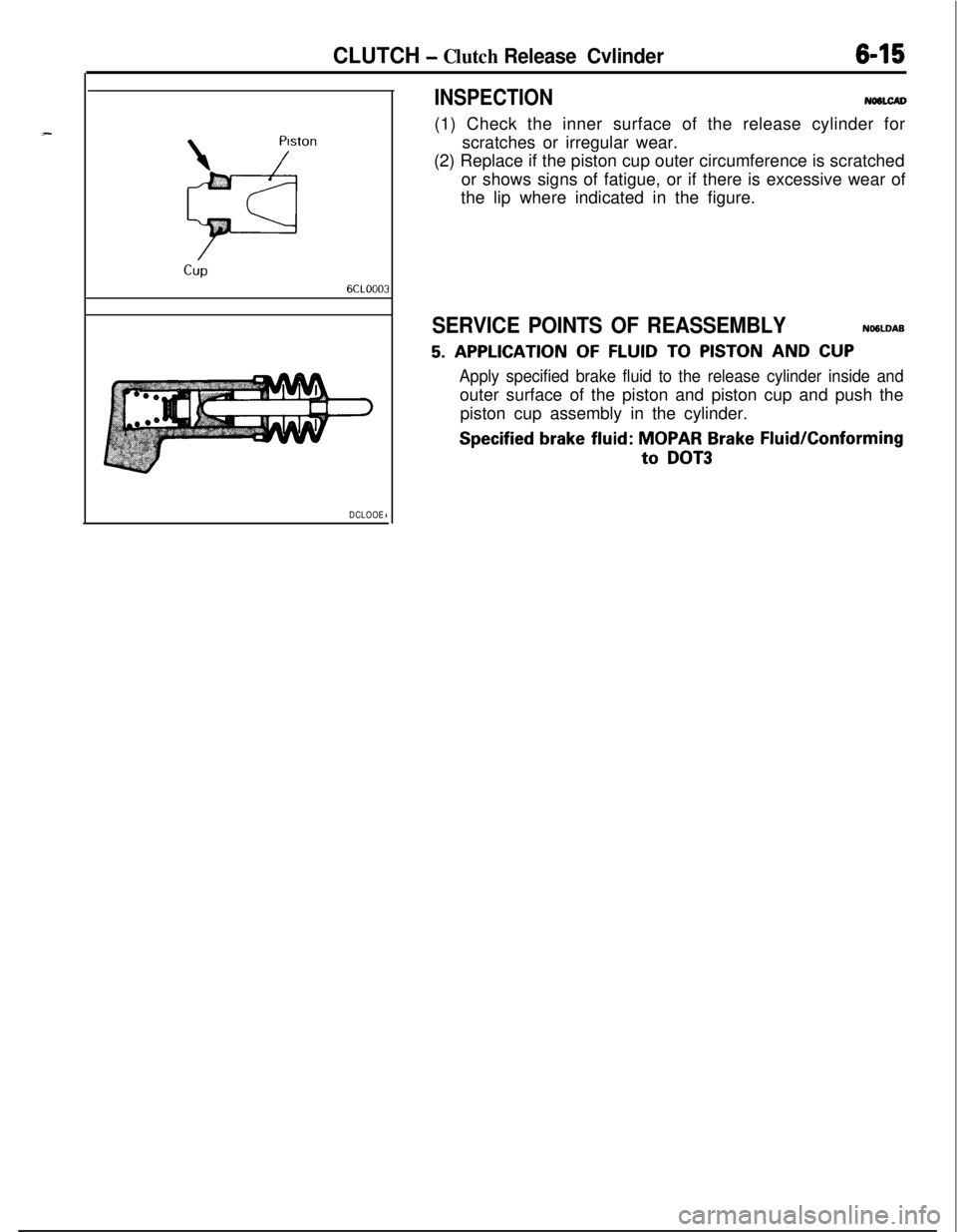
INSPECTIONNWLCAV(1) Check the inner surface of the release cylinder for
scratches or irregular wear.
(2) Replace if the piston cup outer circumference is scratched
or shows signs of fatigue, or if there is excessive wear of
the lip where indicated in the figure.
SERVICE POINTS OF REASSEMBLYNO6LDAB
5. APPLICATION OF FLUID TO PISTON AND CUP
Apply specified brake fluid to the release cylinder inside andouter surface of the piston and piston cup and push the
piston cup assembly in the cylinder.
Specified brake fluid: MOPAR Brake Fluid/Conforming
to DOT3
Page 695 of 1216
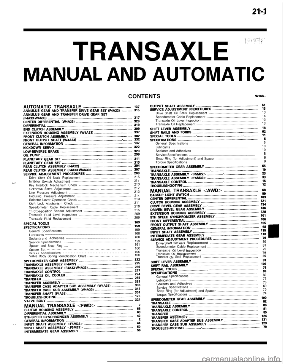
TRANSAXLE ’
MANUAL AND AUTOMATICCONTENTS
;-AUTOMATICTRANSAXLE
.....................................................137ANNULUS GEAR AND TRANSFER DRIVE GEAR SET (F4A22)..........315ANNULUS GEAR AND TRANSFER DRIVE GEAR SET(F4A33.W4A33)...........................................................................................317CENTERDIFFERENTIAL(W4A33).............................................................329DIFFERENTIAL............................................................................................319ENDCLUTCHASSEMBLY.........................................................................309EXTENSIONHOUSINGASSEMBLY(W4A33).........................................337FRONTCLUTCHASSEMBLY....................................................................302FRONTOUTPUTSHAFT(W4A33)...........................................................332GENERALINFORMATION.........................................................................137KICKDOWNSERVO....................................................................................322LOW-REVERSEBRAKE..............................................................................323OILPUMP...................................................................................................299PLANETARYGEARSET............................................................................311PLANETARYGEARSET............................................................................313REARCLUTCHASSEMBLY(F4A22)........................................................304REARCLUTCHASSEMBLY(FQA33sW4A33)............................................307SERVICEADJUSTMENTPROCEDURES..................................................Drive
Shaft,OilSealsReplacement....................................................;;;
InhibitorSwtchAdjustment................................................................21 1KeyInterlockMechanismCheck.....................................................KrckdownServoAdjustment..................................zii..............................
LinePressureAdjustment...................................................................213
ReducingPressureAdjustment.........................................................214Selector Lever Operation Check........................................................210ShiftLockMechanismCheck...............................................................21 1SpeedometerCableReplacement.........................................................Throttle-posltipn Sensor Adjustment.................................................z2:
TransaxleFluIdLevelInspectIon......................................................209
TransaxleFluidReplacement.............................................................209
SPECIALTOOLS.........................................................................................SPECIFICATIONS........................................................................................;“5”9
GeneralSpeclficatlons..................................................................1%Lubricants..................................................................................Sealants and Adhesives..............................................................izi
Serwce Speclflcatlons..................................................159...............Spacer andSnapRing.,.,.............................................................Spacer Set..................................................................1::Torque Speclflcatlons...........................................166Valve Body Spring Identification Chart.....................
.................160
SPEEDOMETERGEARASSEMBLY..........................................................TRANSAXLEASSEMBLY(WA22)............................................................zTRANSAXLE
ASSEMBLY(F4A33.W4A33)................................................TRANSAXLECONTROL.............................................................................;;;TRANSAXLE
OILCOOLER........................................................................TRANSFER..................................................................................................fg
TRANSFERASSEMBLY.............................................................................333TRANSFERCASEADAPTERSUBASSEMBLY(W4A33).......................339TRANSFER CASE SUB ASSEMBLY (W4A33)341TRANSFER SHAFT (F4A33)TROUBLESHOOTING..................................................................................................................................................................................................f;;VALVE
BODY.............................................................................................324
MANUAL TRANSAXLE
5TH-SPEEDSYNCHRONIZERASSEMBLY...............................................42GENERALINFORMATION.........................................................................2.-.INPUTfj,-,A,TASSEMBLY
INTERMEDIATE GEAR ASSEMBLY..........................................................56OUTPUT
SHAFT ASSEMBLY....................................................................61SERVICEADJUSTMENTPROCEDURES..................................................DriveShaftOilSealsReplacement......................................................;;Speedometer Cable Replacement.........................................................
Transaxle Oil Level
InspectIon..............................................................‘liTransaxle Oil Replacement....................................................................
I3
SHIFTLEVERASSEMBLY.........................................................................SHIFTRAILSANDFORKS........................................................................g
SPECIALTOOLS.........................................................................................SPECIFICATIONS........................................................................................1:
General Specifications5Lubricants..........................................................................................................................................................................10Sealants and Adhesives
Service Specifications
....................................................................................................................................................1:Snap Ring (for Adjustment) and Spacer...............................................
Torque Specifications.............................................................................
i
SPEEDOMETERGEARASSEMBLY..........................................................TRANS&G.E................................................................................................zTRANSAXLEA!jSEMBLY
TROUBLESHOOTING..................................................................................12
MANUAL TRANSAXLE
CENTERDIFFERENTIAL.............................................................................103CLUTCHHOUSINGASSEMBLY...............................................................DRIVE BEVEL GEAR ASSEMBLY;g
...... .......................................................DRIVENBEVELGEARASSEMBLY...................................a......................EXTENSIONHOUSINGASSEMBLY.........................................................;g
5Tf.jSPEEDSYNCHRONIZERASSEMBLY...............................................101
FRONTDlFFERENTlAL...............................................................................106
FRONTOUTPUTSHAFTASSEMBLY......................................................106
GENERALI~~~~MATN)N...............................................................,.,.......66INPUTSHAFTASSEMBLY........................................................................l~ER,“,EDlATEGEARASSMBLY..........................................................;;i
SERVICEADJUSTMENTPROCEDURES..................................................Drive Shaft Oil Seals Replacement......................................................;;Speedometer Cable Replacement.........................................................
Transaxle
Ojl Level lnspectlon..............................................................;l
Transaxle 011 R~pb33ment....................................................................79Transfer
OilSealReplacement.............................................................80
SHIFTLEVERASSEMBLY.........................................................................SHIFTRAILASSEMBLY............................................................................,z
SPECIALTOOLS.........................................................................................76
SPECIFICATIONS........................................................................................6g
GeneralSpecifications...........................................................................6g
Lubricants...............................................................................................75
SealantsandAdhesives........................................................................76
ServiceSpecifications............................................................................6gSnap Ring (for Adjustment) and Spacer...............................................7 o
TorqueSpecifications.............................................................................74
SPEEDOMETERGEARASSEMBLY..........................................................TRANSAXLE................................................................................................1:TRANSAXLEASSEMBLY...........................................................................86TRANSAXLE
CONTROL
.............................................................................TRANSFER...............................................................................................
g.._TRANSFERA!333lBLY.............................................................................,24
TRANSFERCASEADAPTERSUBASSEMBLY.......................................131TRANSFERCASESUBASSEMBLY.........................................................TR,,UBLES,,OO,,NG..................................................................................1;;