check engine MITSUBISHI ECLIPSE 1991 Service Manual
[x] Cancel search | Manufacturer: MITSUBISHI, Model Year: 1991, Model line: ECLIPSE, Model: MITSUBISHI ECLIPSE 1991Pages: 1216, PDF Size: 67.42 MB
Page 6 of 1216
6INTRODUCTION AND MASTER TROUBLESHOOTING - Vehicle Identificetion
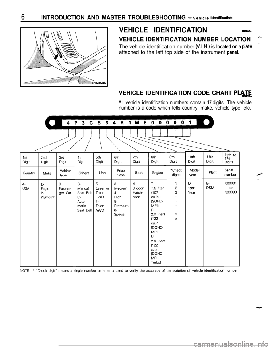
VEHICLE IDENTIFICATIONNmx-VEHICLE IDENTIFICATION NUMBER LOCATION
The vehicle identification number
(V.I.N.) is located oh a plate
attached to the left top side of the instrument panel.
VEHICLE IDENTIFICATION CODE CHART
PLA.4
All vehicle identification numbers contain 17 digits. The vehicle
number is a code which tells country, make, vehicle type, etc.
\5thDigit
r8thDigitr9thDigit
11thDigit12th to17thDigits
10thDigitModelyearM-
1991Year
7thDigitBody
4-
3 doorHatch-back
Engine
T-1.8 liter
(107cu.in.)[SOHC-MPI1R-2.0 liters(122
cu.in.)
[DOHC-
MPI]
u-2.0 liters
(122cuin.)[DOHC-MPI-Turbo]6thDigit
Price
class
3-Medium
4-
High5-Premium
6-Special
4thDigit
Others
B-Manual
Seat Beltc-
Auto-matic
Seat Belt
3rdDigitVehicleWe
3-Passen-ger
Car
2ndDigitMake
E-EagleP-Plymouth
1stDigitCountry
4-
USA
Serialnumber*CheckPlantLine
E-DSMS-Laser or
TalonFWDT-Talon
AWD
000001to
999999
I
NOTE* “Check digit” means a single number or letter x used to verify the accuracy of transcription of vehicle identification number.
Page 14 of 1216
I4INTRODUCTION AND MASTER TROUBLESHOOTING - Precautions before Service
mm (In.1smo59
PARTSWhen replacing parts, use MOPAR genuine parts.
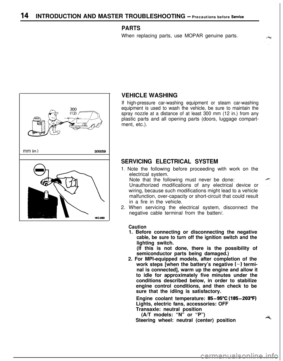
VEHICLE WASHING
If high-pressure car-washing equipment or steam car-washing
equipment is used to wash the vehicle, be sure to maintain the
spray nozzle at a distance of at least 300 mm (12 in.) from anyplastic parts and all opening parts (doors, luggage compart-
ment, etc.).
SERVICING ELECTRICAL SYSTEM
1. Note the following before proceeding with work on the
electrical system.
Note that the following must never be done:
Unauthorized modifications of any electrical device or
wiring, because such modifications might lead to a vehicle
malfunction, over-capacity or short-circuit that could result
in a fire in the vehicle.
2. When servicing the electrical system, disconnect the
negative cable terminal from the batten/.
Caution1. Before connecting or disconnecting the negative
cable, be sure to turn off the ignition switch and thelighting switch.
(If this is not done, there is the possibility of
semiconductor parts being damaged.)
2. For MPI-equipped models, after completion of the
work steps [when the battery’s negative
(-) termi-
nal is connected], warm up the engine and allow it
to idle for approximately five minutes under the
conditions described below, in order to stabilize
engine control conditions, and then check to be
sure that the idling is satisfactory.
Engine coolant temperature:
85-95°C (185-203°F)
Lights, electric fans, accessories: OFF
Transaxle: neutral position
(A/T models: “N” or “P”)
Steering wheel: neutral (center) position
Page 24 of 1216
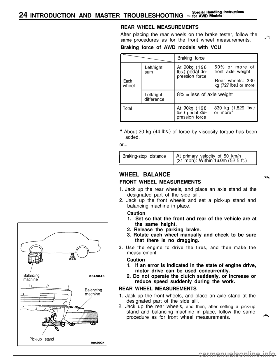
24 INTRODUCTION AND MASTER TROUBLESHOOTING - fSo%k%:~~it’ndrU~ionsREAR WHEEL MEASUREMENTS
After placing the rear wheels on the brake tester, follow the
same procedures as for the front wheel measurements.
,’
~.Braking force of AWD models with VCU
Balancing
machine
Pick-up stand
WA0024
Braking force
EachwheelLeft/right
sumLeft/right
differenceAt
90kg (19860% or more ofIbs.) pedal de-front axle weightpression force
Rear wheels: 330
kg (727 Ibs.) or more8% or less of axle weight
TotalAt 90kg (198830 kg (1,829 Ibs.)
Ibs.) pedal de-or more*pression force
* About 20 kg (44 Ibs.) of force by viscosity torque has been
added.
or...
I
Braking-stop distanceAt primary velocity of 50 km/h
(31 mph): Within 16.0m (52.5 ft.)
WHEEL BALANCE.r=lFRONT WHEEL MEASUREMENTS
1. Jack up the rear wheels, and place an axle stand at the
designated part of the side sill.
2. Jack up the front wheels and set a pick-up stand and
balancing machine in place.
Caution
1.Set so that the front and rear of the vehicle are at
the same height.
2. Release the parking brake.
3. Rotate each wheel manually and check to be sure
that there is no dragging.
3. Use the engine to drive the tires, and then make the
measurement.Caution
1.If an error is indicated in the state of engine drive,
motor drive can be used concurrently.
2. Do not operate the clutch
suddenly, or increase or
reduce speed suddenly during the work.
REAR WHEEL MEASUREMENTS
1. Jack up the front wheels, and place an axle stand at the
designated part of the side sill.
2. Jack up the rear wheels, and then, after setting a pick-up
stand and balancing machine in place, follow the same
procedure as for front wheel measurements.
.&,
Page 29 of 1216
INTRODUCTION AND MASTER TROUBLESHOOTING - Mast& Tro6blerhootbia
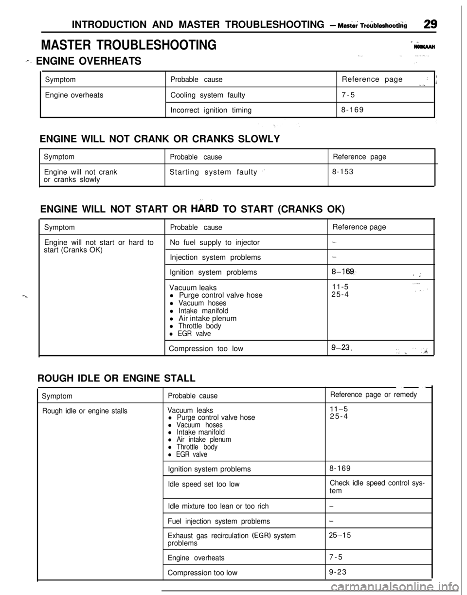
MASTER TROUBLESHOOTING7 *
I,._ ,...
r. ENGINE OVERHEATSi ”
SymptomEngine overheatsProbable causeCooling system faulty
Incorrect ignition timingReference page: I._),7-5
8-169
ENGINE WILL NOT CRANK OR CRANKS SLOWLY
SymptomEngine will not crank
or cranks slowlyProbable causeStarting system faulty
,’
Reference page8-153
ENGINE WILL NOT START OR
HbRD TO START (CRANKS OK)
SymptomProbable causeReference page
Engine will not start or hard toNo fuel supply to injector
-start (Cranks OK)
Injection system problems
-Ignition system problems
8-16!$/ ”;Vacuum leaks11-5..“,:’l Purge control valve hose25-4
l Vacuum hoses
l Intake manifoldl Air intake plenum
l Throttle body
l EGR valveCompression too low
g-23,‘, :. ” ‘,;A;ROUGH IDLE OR ENGINE STALL
Symptom
Rough idle or engine stallsProbable cause
Vacuum leaks
l Purge control valve hosel Vacuum hosesl Intake manifoldl Air intake plenuml Throttle bodyl EGR valve
“. ._
Reference page or remedy
11-525-4
Ignition system problems
Idle speed set too low8-169Check idle speed control sys-
tem
Idle mixture too lean or too rich
Fuel injection system problems
Exhaust gas recirculation
(EGR) system
problems
Engine overheatsCompression too low
-
-
25-l 57-5
9-23
Page 37 of 1216
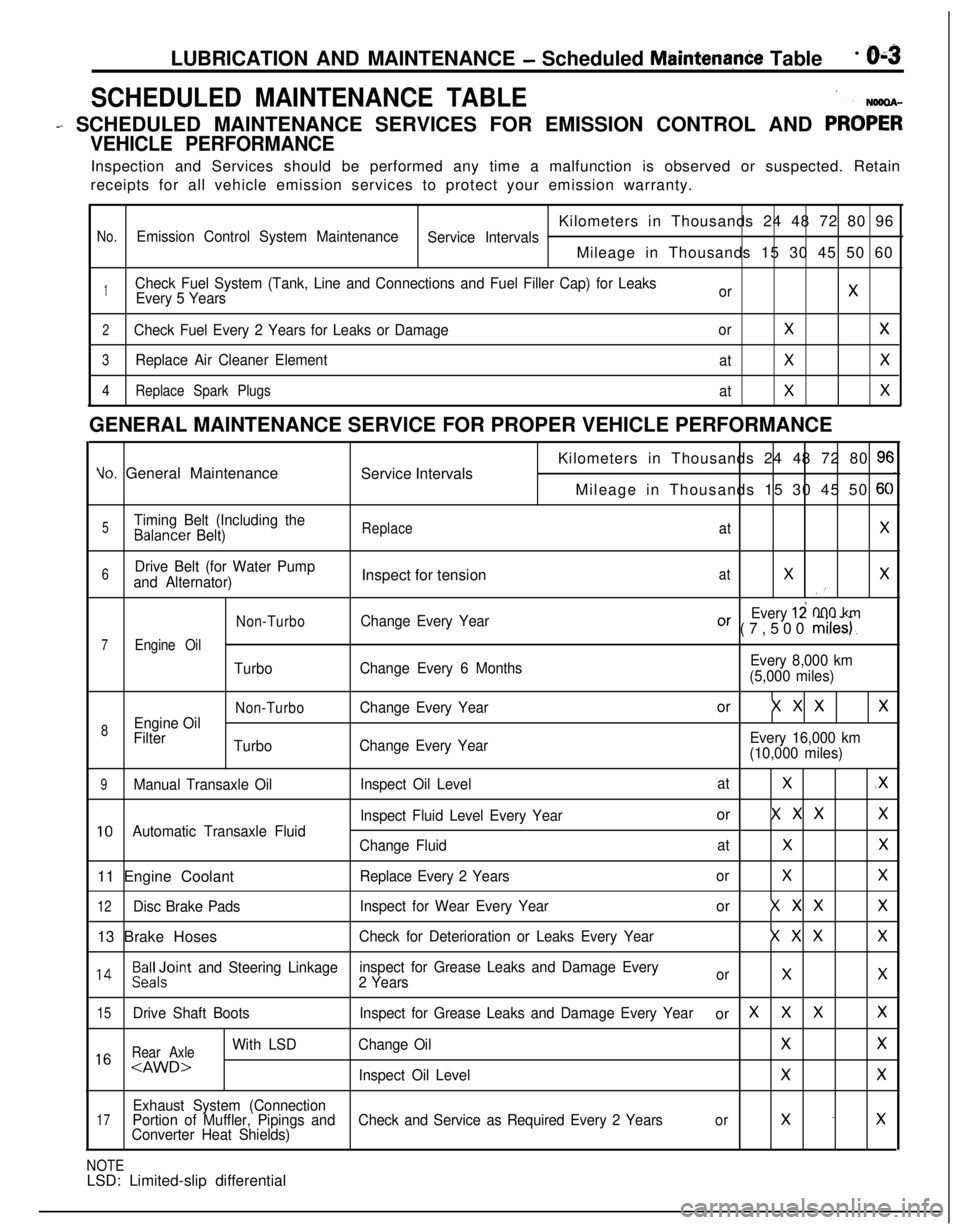
LUBRICATION AND MAINTENANCE - Scheduled MaintenanCe Table. &3
SCHEDULED MAINTENANCE TABLE1
- SCHEDULED MAINTENANCE SERVICES FOR EMISSION CONTROL AND PRO;;
VEHICLE PERFORMANCEInspection and Services should be performed any time a malfunction is observed or suspected. Retain
receipts for all vehicle emission services to protect your emission warranty.
Kilometers in Thousands 24 48 72 80 96
No.Emission Control System Maintenance
Service IntervalsMileage in Thousands 15 30 45 50 60
1Check Fuel System (Tank, Line and Connections and Fuel Filler Cap) for Leaks
Every 5 YearsorX
2Check Fuel Every 2 Years for Leaks or DamageorXX
3Replace Air Cleaner Element
atXX
4Replace Spark Plugs
atXXGENERAL MAINTENANCE SERVICE FOR PROPER VEHICLE PERFORMANCE
Yo. General Maintenance
Service IntervalsKilometers in Thousands 24 48 72 80 9cMileage in Thousands 15 30 45 50
6C
5Timing Belt (Including theBalancer Belt)ReplaceatX
6Drive Belt (for Water Pump
and Alternator)Inspect for tensionatXX.’
Non-TurboChange Every YearEvery 12 000 kmOr (7,500 miles).
7Engine Oil
TurboChange Every 6 MonthsEvery 8,000 km
(5,000 miles)
Non-TurboChange Every Yearor X X XX
8Engine Oil
Filter
TurboChange Every YearEvery 16,000 km
(10,000 miles)
9Manual Transaxle OilInspect Oil LevelatX.X
Inspect Fluid Level Every Yearor X X XX
10Automatic Transaxle Fluid
Change FluidatXX11 Engine Coolant
Replace Every 2 YearsorXX
12Disc Brake PadsInspect for Wear Every Yearor X X XX13 Brake Hoses
Check for Deterioration or Leaks Every YearX X XX
l 4Beiloint and Steering Linkageinspect for Grease Leaks and Damage Every
2 YearsorXX
15Drive Shaft BootsInspect for Grease Leaks and Damage Every Yearor XXXX
Rear Axle
With LSDChange OilXX1 6
Exhaust System (Connection17Portion of Muffler, Pipings andCheck and Service as Required Every 2 Yearsorx -xConverter Heat Shields)
NOTELSD: Limited-slip differential
Page 41 of 1216
LUBRICATION AND MAINTENANCE - Maintenance Service
MAINTENANCE SERVICE1. FUEL SYSTEM (Tank, Lines,
Connect%ms and
Fuel Filler Cap) (Check for
leaks)/2. FUEL
HOSE (Check for leaks or
damage)1 NSOSAGtib1. Check for damage or leakage in the fuet
lines and
connections and looseness of the fuel
fi!:ler cap.
2.Inspect the surface of fuel hoses for heat and mecha-
nical damage. Hard and brittle rubber, cracking, check-
ing, tears, cuts, abrasions and excessive swelling
indicate deterioration of the rubber.
3. If the fabric casing of the rubber hose is exposed by
cracks and abrasions in the fuel system, the hoses
should be changed.
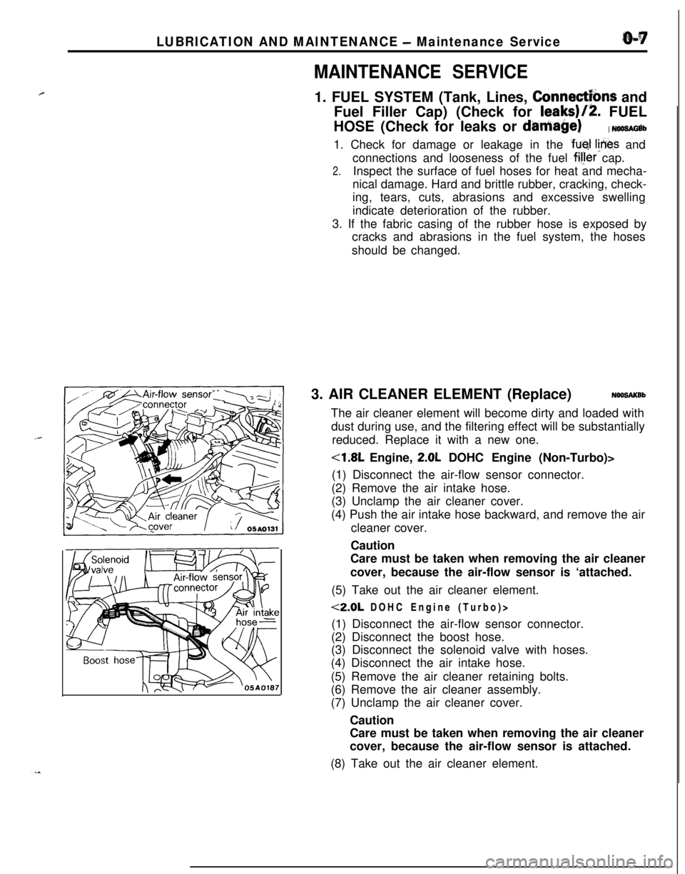
3. AIR CLEANER ELEMENT (Replace)
NOOSAKBbThe air cleaner element will become dirty and loaded with
dust during use, and the filtering effect will be substantially
reduced. Replace it with a new one.
<1.8L Engine, 2.0L DOHC Engine (Non-Turbo)>
(1) Disconnect the air-flow sensor connector.
(2) Remove the air intake hose.
(3) Unclamp the air cleaner cover.
(4) Push the air intake hose backward, and remove the air
cleaner cover.
Caution
Care must be taken when removing the air cleaner
cover, because the air-flow sensor is ‘attached.
(5) Take out the air cleaner element.
<2.0L DOHC Engine (Turbo)>
(1) Disconnect the air-flow sensor connector.
(2) Disconnect the boost hose.
(3) Disconnect the solenoid valve with hoses.
(4) Disconnect the air intake hose.
(5) Remove the air cleaner retaining bolts.
(6) Remove the air cleaner assembly.
(7) Unclamp the air cleaner cover.
Caution
Care must be taken when removing the air cleaner
cover, because the air-flow sensor is attached.
(8) Take out the air cleaner element.
Page 42 of 1216
O-8LUBRICATION AND MAINTENANCE - Maintenance Service
0-L
I-TOlLO182
-
, ,6COOO9
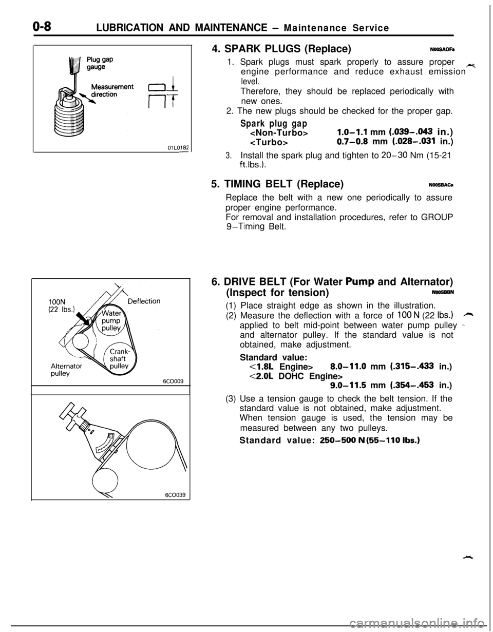
u6COO394. SPARK PLUGS (Replace)
NOOSAOFa1. Spark plugs must spark properly to assure proper
~engine performance and reduce exhaust emission
level.Therefore, they should be replaced periodically with
new ones.
2. The new plugs should be checked for the proper gap.
Spark plug gap
1.0-1.1 mm (.039-.043 in.)
0.7-0.8 mm (.028-.031 in.)
3.Install the spark plug and tighten to 20-30 Nm (15-21
ft.lbs.).5. TIMING BELT (Replace)
NOOSBACaReplace the belt with a new one periodically to assure
proper engine performance.
For removal and installation procedures, refer to GROUP
g-Timing Belt.
6. DRIVE BELT (For Water
Pump and Alternator)
(Inspect for tension)
NOOSSBN(1) Place straight edge as shown in the illustration.
(2) Measure the deflection with a force of
100 N (22 Ibs.)rzapplied to belt mid-point between water pump pulley
-and alternator pulley. If the standard value is not
obtained, make adjustment.
Standard value:
<1.8L Engine>8.0-11.0 mm (.315-A33 in.)
<2.0L DOHC Engine>
9.0-11.5 mm (.354-.453 in.)
(3) Use a tension gauge to check the belt tension. If the
standard value is not obtained, make adjustment.
When tension gauge is used, the tension may be
measured between any two pulleys.
Standard value:
250-500 N (55-110 Ibs.)
Page 43 of 1216
LUBRICATION AND MAINTENANCE - Maintenance ServiceO-9
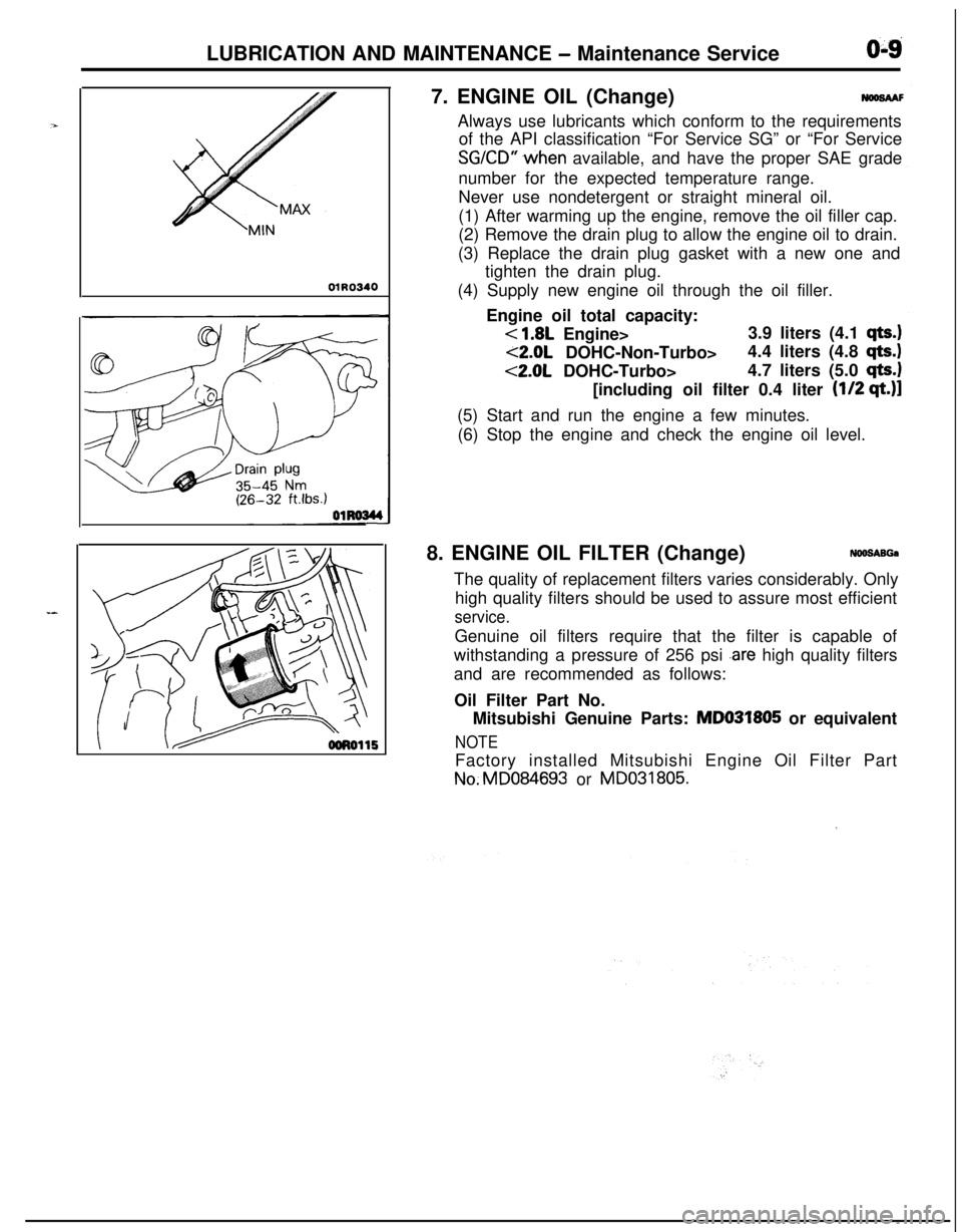
01R03407. ENGINE OIL (Change)
NWSAAFAlways use lubricants which conform to the requirements
of the API classification “For Service SG” or “For Service
SGKD” .when available, and have the proper SAE grade
number for the expected temperature range.
Never use nondetergent or straight mineral oil.
(1) After warming up the engine, remove the oil filler cap.
(2) Remove the drain plug to allow the engine oil to drain.
(3) Replace the drain plug gasket with a new one and
tighten the drain plug.
(4) Supply new engine oil through the oil filler.
Engine oil total capacity:
< 1.8L Engine>3.9 liters (4.1 qts.)
<2.0L DOHC-Non-Turbo>4.4 liters (4.8 qts.)
<2.0L DOHC-Turbo>4.7 liters (5.0 qts.1[including oil filter 0.4 liter
(l/2 qt.)]
(5) Start and run the engine a few minutes.
(6) Stop the engine and check the engine oil level.
8. ENGINE OIL FILTER (Change)
NOO!SABGaThe quality of replacement filters varies considerably. Only
high quality filters should be used to assure most efficient
service.Genuine oil filters require that the filter is capable of
withstanding a pressure of 256 psi
.are high quality filters
and are recommended as follows:
Oil Filter Part No.
Mitsubishi Genuine Parts: MD031805 or equivalent
NOTEFactory installed Mitsubishi Engine Oil Filter PartNo.MD084693 or MD031805.
’
Page 44 of 1216
LUBRICATION AND MAINTENANCE - Maintenance Service
osFol2ENGINE
OIL FtLTER SELECTtONThis vehicle is equipped with a full-flow, throw-away oil
,~
filter.The same type of replacement filter is recommended as a
replacement filter for this vehicle. It is possible, particularilyin cold weather, that this vehicle may develop high oil
pressure for a short duration. You should be sure that any
replacement filter used on this vehicle is a high-quality filterand is capable of withstanding a pressure of 256 psi
(manufacturer’s specifications) to avoid filter and engine
damage. The following is a high-quality filter and is stronglyrecommended for use on this vehicle
: Mitsubishi Engine
-Oil Filter Part No. MD031805 or MD084693.
Any replacement oil filter should be installed in accordancewith the oil filter manufacturer’s installation instructions.
(1) Remove the engine oil filler cap.
(2) Remove the engine oil drain plug, and drain out the
engine oil.
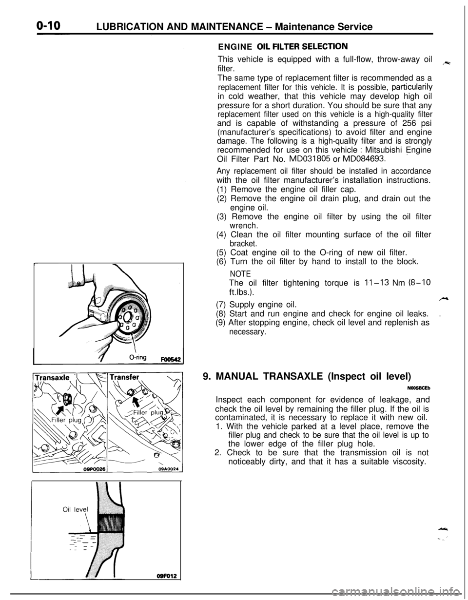
(3) Remove the engine oil filter by using the oil filter
wrench.(4) Clean the oil filter mounting surface of the oil filter
bracket.(5) Coat engine oil to the O-ring of new oil filter.
(6) Turn the oil filter by hand to install to the block.
NOTEThe oil filter tightening torque is
11-13 Nm (8-10
ftlbs.).A(7) Supply engine oil.
.(8) Start and run engine and check for engine oil leaks.
(9) After stopping engine, check oil level and replenish as
necessary.9. MANUAL TRANSAXLE (Inspect oil level)
NOOSBCEbInspect each component for evidence of leakage, and
check the oil level by remaining the filler plug. If the oil is
contaminated, it is necessary to replace it with new oil.
1. With the vehicle parked at a level place, remove the
filler plug and check to be sure that the oil level is up tothe lower edge of the filler plug hole.
2. Check to be sure that the transmission oil is not
noticeably dirty, and that it has a suitable viscosity.
Page 46 of 1216
LUBRICATION AND MAINTENANCE - Maintenance Service
L-4GoodOOA0051C9FW1014K512(9) Supply 4 liters (8.5 pints) of specified ATF into case
through dipstick hole. [Total quantity of ATF required is
6.1 liters (12.9 pints).
Actually however, approx. 4.5 liters (9.5 pints) of fluid
can be replaced because rest of fluid remains in torque
converter.]Specified fluid: MOPAR ATF PLUS (Automatic
Transmission Fluid Type 7176) or
Dia ATF SP or Equivalent
(10)Start engine and allow to idle for at least two minutes.
Then, with parking brake on, move selector lever
momentarily to each position, ending in “N” Neutral
position.
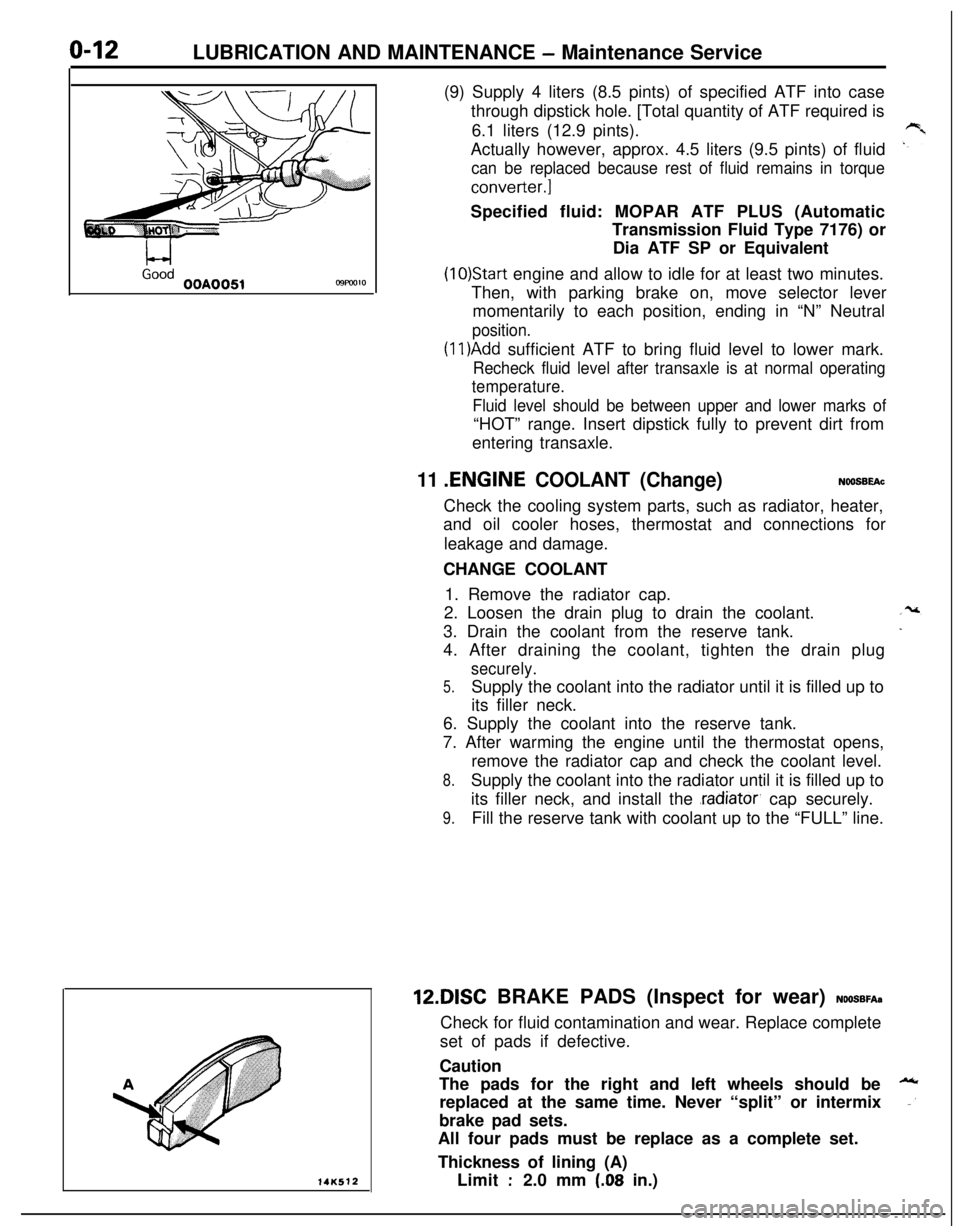
(1 l)Add sufficient ATF to bring fluid level to lower mark.
Recheck fluid level after transaxle is at normal operating
temperature.
Fluid level should be between upper and lower marks of“HOT” range. Insert dipstick fully to prevent dirt from
entering transaxle.
11 .ENGINE COOLANT (Change)NOOSBEAcCheck the cooling system parts, such as radiator, heater,
and oil cooler hoses, thermostat and connections for
leakage and damage.
CHANGE COOLANT
1. Remove the radiator cap.
2. Loosen the drain plug to drain the coolant.
3. Drain the coolant from the reserve tank.
4. After draining the coolant, tighten the drain plug
securely.
5.Supply the coolant into the radiator until it is filled up to
its filler neck.
6. Supply the coolant into the reserve tank.
7. After warming the engine until the thermostat opens,
remove the radiator cap and check the coolant level.
8.Supply the coolant into the radiator until it is filled up to
its filler neck, and install the
.radiator, cap securely.
9.Fill the reserve tank with coolant up to the “FULL” line.12DISC BRAKE PADS (Inspect for wear)
NOOSBFA~Check for fluid contamination and wear. Replace complete
set of pads if defective.
Caution
The pads for the right and left wheels should be
replaced at the same time. Never “split” or intermix
brake pad sets.
All four pads must be replace as a complete set.
Thickness of lining (A)
Limit
:2.0 mm (.08 in.)