check transmission fluid MITSUBISHI ECLIPSE 1991 Service Manual
[x] Cancel search | Manufacturer: MITSUBISHI, Model Year: 1991, Model line: ECLIPSE, Model: MITSUBISHI ECLIPSE 1991Pages: 1216, PDF Size: 67.42 MB
Page 45 of 1216
LUBRICATION AND MAINTENANCE - Maintenance ServiceO:lllO.AUTOMATIC TRANSAXLE (Inspect fluid
I~~+v~!1. Drive until the fluid temperature reaches the usual
temperature
[70-80°C (160- 18O”F)l.2. Place vehicle on level floor.
3.Move selector lever sequentially to every position to fill
torque converter and hydraulic
circuitwith fluid, then
place lever in“N” Neutral position. This operation is
necessary to be sure that fluid level check is accurate.
4.Before removing dipstick, wipe all dirt from area arounddipstick. Then take out the dipstick and check the
condition of the fluid.
The transaxle should be overhauled under the following
conditions.l If there is a “burning” odor.
l If the fluid color has become noticeably blacker.
l If there is a noticeably great amount of metal
particles in the fluid.
5.Check to see if fluid level is in “HOT” range on dipstick.If fluid level is low, add ATF until level reaches “HOT”
range.Low fluid level can cause a variety of conditions
because it allows pump to take in air along with fluid. Airtrapped in hydraulic circuit forms bubbles which make
fluid spongy. Therefore, pressures will be erratic.
Improper filling can also raise fluid level too high. Whentransaxle has too much fluid, gears churn up foam and
cause same conditions which occur with low fluid level,resulting in accelerated deterioration of ATF.
transmission fluid.
In either case, air bubbles can cause overheating, fluid
oxidation, which can interfere with normal valve, clutch,and servo operation. Foaming can also result in fluid
escaping from transaxle vent where it may be mistakenfor a leak.
6. Be sure to examine fluid on dipstick closely.lO.AUTOMATIC TRANSAXLE (Change fluid)
Drain the fluid and check whether there is any evidence of
contamination.
Replenish with new fluid after the cause of any contamina-tion has been corrected.
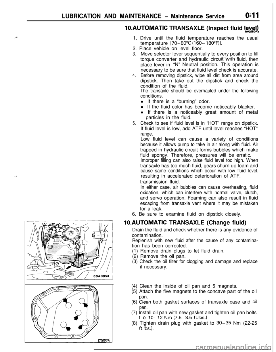
(1) Remove drain plugs to let fluid drain.
(2) Remove the oil pan.
(3) Check the oil filter for clogging and damage and replaceif necessary.
(4) Clean the inside of oil pan and 5 magnets.
(5) Attach the five magnets to the concave part of the oil
(6)
Elan both gasket surfaces of transaxle case and oil
pan.(7) Install oil pan with new gasket and tighten oil pan bolts
to
IO-12 Nm (7.5-8.5 ft.lbs.1(8) Tighten drain plug with gasket to
30-35 Nm (22-25
ftlbs.).
Page 46 of 1216
LUBRICATION AND MAINTENANCE - Maintenance Service
L-4GoodOOA0051C9FW1014K512(9) Supply 4 liters (8.5 pints) of specified ATF into case
through dipstick hole. [Total quantity of ATF required is
6.1 liters (12.9 pints).
Actually however, approx. 4.5 liters (9.5 pints) of fluid
can be replaced because rest of fluid remains in torque
converter.]Specified fluid: MOPAR ATF PLUS (Automatic
Transmission Fluid Type 7176) or
Dia ATF SP or Equivalent
(10)Start engine and allow to idle for at least two minutes.
Then, with parking brake on, move selector lever
momentarily to each position, ending in “N” Neutral
position.
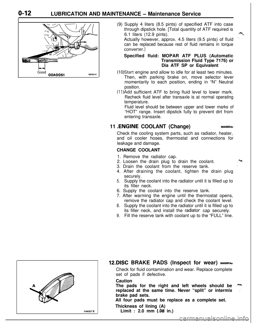
(1 l)Add sufficient ATF to bring fluid level to lower mark.
Recheck fluid level after transaxle is at normal operating
temperature.
Fluid level should be between upper and lower marks of“HOT” range. Insert dipstick fully to prevent dirt from
entering transaxle.
11 .ENGINE COOLANT (Change)NOOSBEAcCheck the cooling system parts, such as radiator, heater,
and oil cooler hoses, thermostat and connections for
leakage and damage.
CHANGE COOLANT
1. Remove the radiator cap.
2. Loosen the drain plug to drain the coolant.
3. Drain the coolant from the reserve tank.
4. After draining the coolant, tighten the drain plug
securely.
5.Supply the coolant into the radiator until it is filled up to
its filler neck.
6. Supply the coolant into the reserve tank.
7. After warming the engine until the thermostat opens,
remove the radiator cap and check the coolant level.
8.Supply the coolant into the radiator until it is filled up to
its filler neck, and install the
.radiator, cap securely.
9.Fill the reserve tank with coolant up to the “FULL” line.12DISC BRAKE PADS (Inspect for wear)
NOOSBFA~Check for fluid contamination and wear. Replace complete
set of pads if defective.
Caution
The pads for the right and left wheels should be
replaced at the same time. Never “split” or intermix
brake pad sets.
All four pads must be replace as a complete set.
Thickness of lining (A)
Limit
:2.0 mm (.08 in.)
Page 692 of 1216
19-44STEERING - Power Steering Oil Pump
13AO350
13PO159
Punch mark
13c214 I
13W03ECutouts for
dowel pin
13PO16110. INSTALLATION OF
O-RING/S. O-RING
Apply specified fluid on O-ring to install.
-,Specified fluid: MOPAR ATF PLUS (Automatic
Trans- ”mission Fluid Type 7176)/Automatic
transmission fluid
“DEXRONY or “DE-XRON II”
1 No. 1I.D. x Widthmm (in.)Identification color
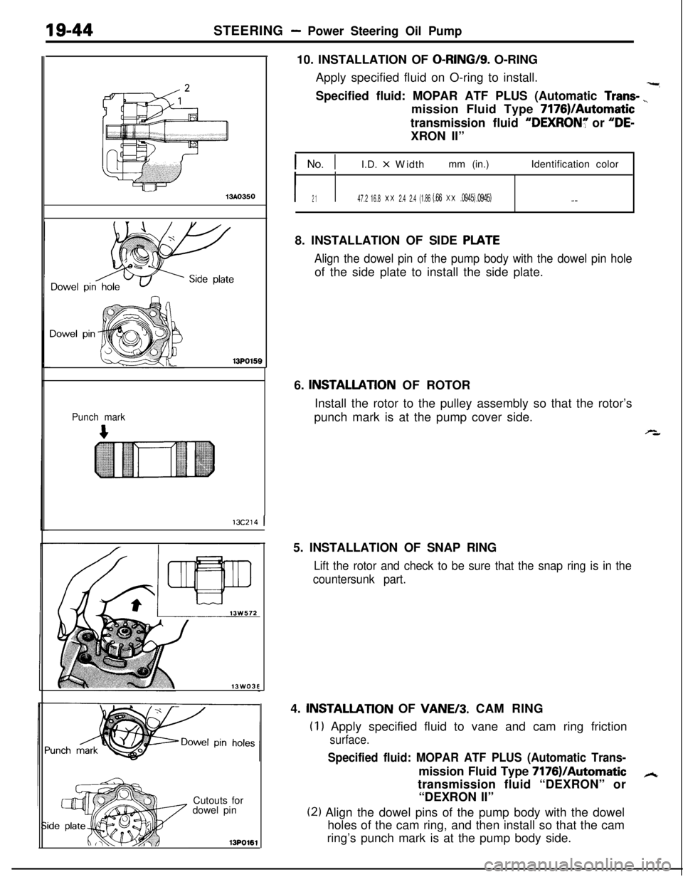
I2 1I47.2 16.8x x2.4 2.4(1.86 (.66x x.0945) .0945)- -8. INSTALLATION OF SIDE
PLATE
Align the dowel pin of the pump body with the dowel pin holeof the side plate to install the side plate.
6.
INSTALLATlON OF ROTOR
Install the rotor to the pulley assembly so that the rotor’s
punch mark is at the pump cover side.
s,5. INSTALLATION OF SNAP RING
Lift the rotor and check to be sure that the snap ring is in the
countersunk part.4.
INSTALLATlON OF VANE/3. CAM RING
(I1 Apply specified fluid to vane and cam ring friction
surface.
Specified fluid: MOPAR ATF PLUS (Automatic Trans-mission Fluid Type 7176)IAutomatic
Atransmission fluid “DEXRON” or
“DEXRON II”
(21 Align the dowel pins of the pump body with the dowel
holes of the cam ring, and then install so that the cam
ring’s punch mark is at the pump body side.
Page 948 of 1216
AUTOMATIC TRANSAXLE - Transaxle Assemblv
Solder
220004858. Install new O-ring in groove of oil pump housing and apply
automatic transmission fluid lightly to outside surface of
O-ring.e59. Install oil pump assembly by tightening six bolts evenly.
i-When installing this oil pump assembly, be careful that
thrust washer will not drop.
60. Check input shaft end play. Readjust if necessary (see step
53).Standard value
: 0.3-1.0 mm (.012-,040 in.)
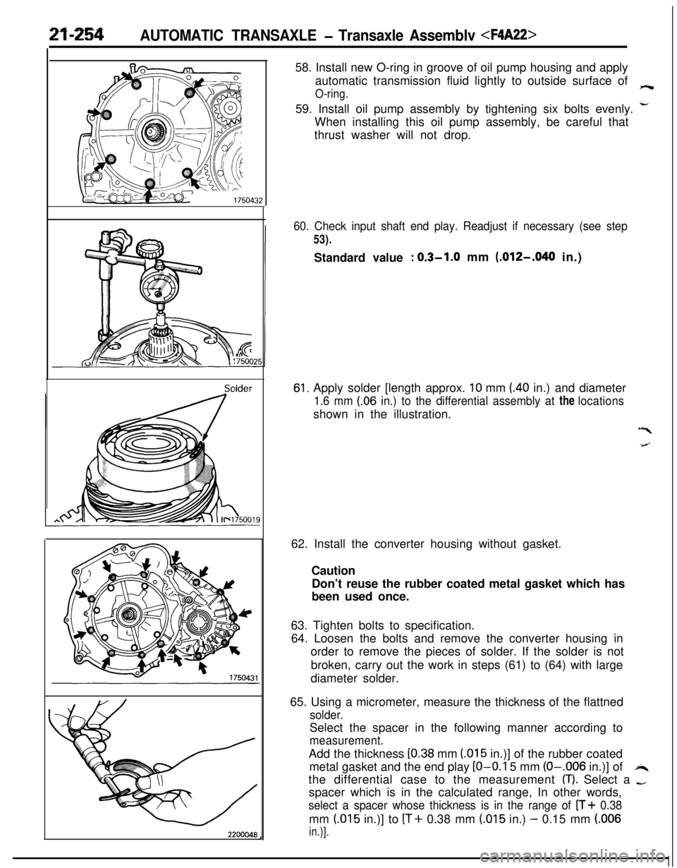
61, Apply solder [length approx. 10 mm (40 in.) and diameter
1.6 mm (.06 in.) to the differential assembly at the locationsshown in the illustration.
“I
-4--J62. Install the converter housing without gasket.
Caution
Don’t reuse the rubber coated metal gasket which has
been used once.
63. Tighten bolts to specification.
64. Loosen the bolts and remove the converter housing in
order to remove the pieces of solder. If the solder is not
broken, carry out the work in steps (61) to (64) with large
diameter solder.
65. Using a micrometer, measure the thickness of the flattned
solder.Select the spacer in the following manner according to
measurement.Add the thickness
[0.38 mm (015 in.)] of the rubber coated
metal gasket and the end play
LO-O.1 5 mm (O-.006 in.)] ofi4the differential case to the measurement
(T). Select a -spacer which is in the calculated range, In other words,
select a spacer whose thickness is in the range of n+ 0.38mm
(.015 in.)] to [T+ 0.38 mm (.015 in.) - 0.15 mm (.006
in.)].
Page 992 of 1216
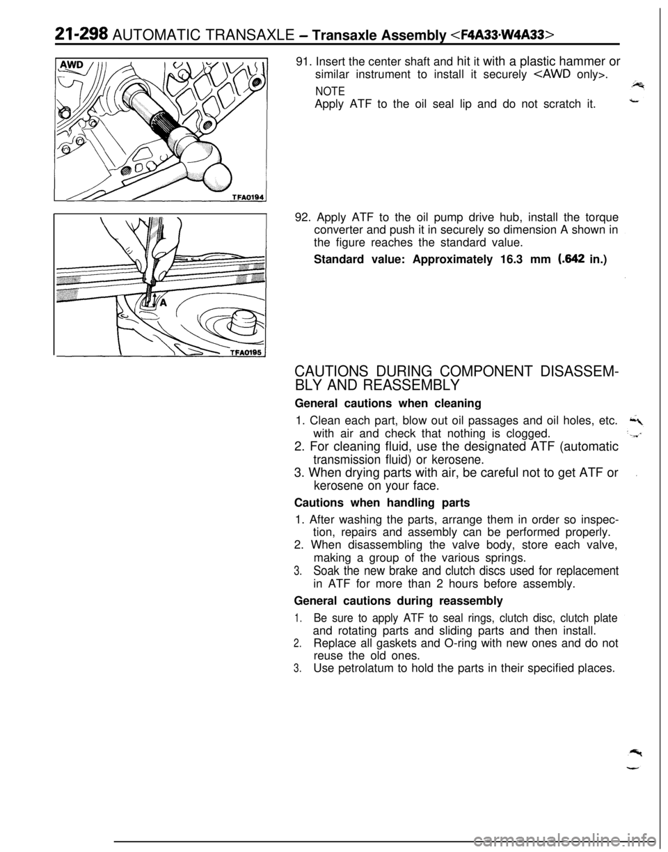
21-298 AUTOMATIC TRANSAXLE - Transaxle Assembly
similar instrument to install it securely
NOTEApply ATF to the oil seal lip and do not scratch it.
92. Apply ATF to the oil pump drive hub, install the torque
converter and push it in securely so dimension A shown in
the figure reaches the standard value.
Standard value: Approximately 16.3 mm
(.642 in.)
CAUTIONS DURING COMPONENT DISASSEM-
BLY AND REASSEMBLYGeneral cautions when cleaning
1. Clean each part, blow out oil passages and oil holes, etc.
with air and check that nothing is clogged.
2. For cleaning fluid, use the designated ATF (automatic
transmission fluid) or kerosene.3. When drying parts with air, be careful not to get ATF or
kerosene on your face.Cautions when handling parts
1. After washing the parts, arrange them in order so inspec-
tion, repairs and assembly can be performed properly.
2. When disassembling the valve body, store each valve,
making a group of the various springs.
3.Soak the new brake and clutch discs used for replacementin ATF for more than 2 hours before assembly.
General cautions during reassembly
1.Be sure to apply ATF to seal rings, clutch disc, clutch plateand rotating parts and sliding parts and then install.
2.Replace all gaskets and O-ring with new ones and do not
reuse the old ones.
3.Use petrolatum to hold the parts in their specified places.
Page 997 of 1216
AUTOMATIC TRANSAXLE - Front Clutch Assemblv21-303
1750266
MD998337
\
1750264
/TFA0498Clutch
reactior
TFA0424
i
269
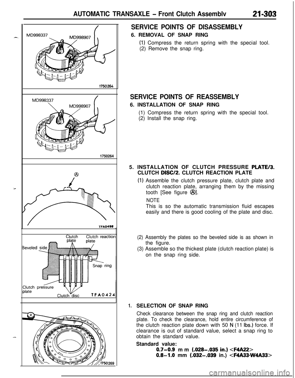
SERVICE POINTS OF DISASSEMBLY6. REMOVAL OF SNAP RING
(1) Compress the return spring with the special tool.
(2) Remove the snap ring.
SERVICE POINTS OF REASSEMBLY6. INSTALLATION OF SNAP RING
(1) Compress the return spring with the special tool.
(2) Install the snap ring.
5. INSTALLATION OF CLUTCH PRESSURE
PLATE/3.CLUTCH
DISC/P. CLUTCH REACTION PLATE
(1) Assemble the clutch pressure plate, clutch plate and
clutch reaction plate, arranging them by the missing
tooth [See figure
@I.
NOTEThis is so the automatic transmission fluid escapes
easily and there is good cooling of the plate and disc.
(2) Assembly the plates so the beveled side is as shown inthe figure.
(3) Assemble so the thickest plate (clutch reaction plate) is
on the snap ring side.
1.SELECTION OF SNAP RING
Check clearance between the snap ring and clutch reaction
plate. To check the clearance, hold entire circumference ofthe clutch reaction plate down with 50
N (11 Ibs.) force. If
clearance is out of standard value, select a snap ring to
obtain the standard value.
Standard value:
0.7-0.9 mm (.028-.035 in;)
0.8-1.0 mm (.032-.039 in.)
Page 1002 of 1216
21-308 AUTOMATIC TRANSAXLE - Rear Clutch Assembly
@
/
(
TFAO240SERVICE POINTS OF
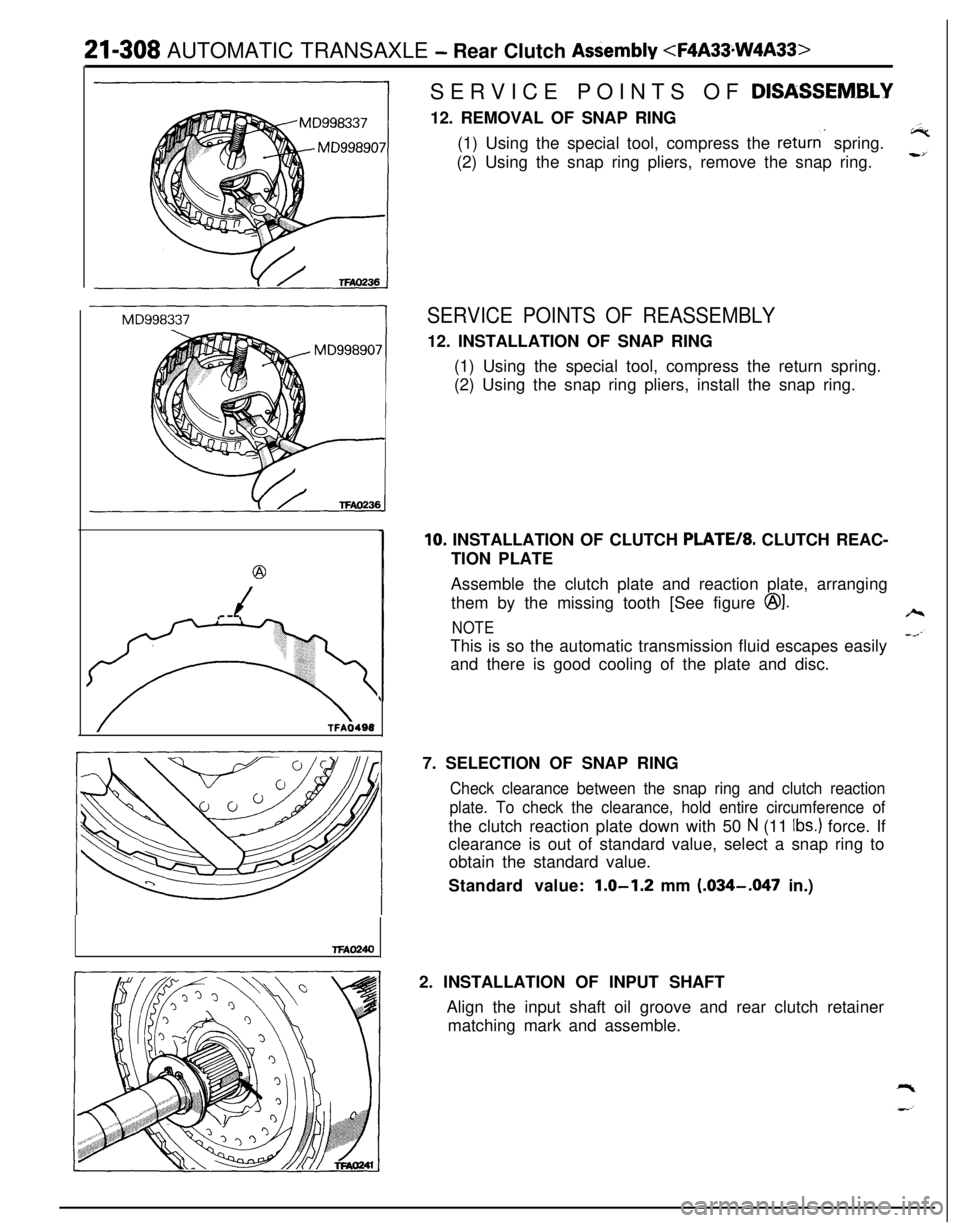
DISASSEM.BLY12. REMOVAL OF SNAP RING
(1) Using the special tool, compress the
returns spring.
(2) Using the snap ring pliers, remove the snap ring.
SERVICE POINTS OF REASSEMBLY12. INSTALLATION OF SNAP RING
(1) Using the special tool, compress the return spring.
(2) Using the snap ring pliers, install the snap ring.
10. INSTALLATION OF CLUTCH PLATE/*. CLUTCH REAC-
TION PLATE
Assemble the clutch plate and reaction plate, arranging
them by the missing tooth [See figure
@I.
NOTEThis is so the automatic transmission fluid escapes easily
and there is good cooling of the plate and disc.
7. SELECTION OF SNAP RING
Check clearance between the snap ring and clutch reaction
plate. To check the clearance, hold entire circumference ofthe clutch reaction plate down with 50
N (11 Ibs.) force. If
clearance is out of standard value, select a snap ring to
obtain the standard value.
Standard value:
1.0-1.2 mm (.034-.047 in.)
2. INSTALLATION OF INPUT SHAFT
Align the input shaft oil groove and rear clutch retainer
matching mark and assemble.