check engine MITSUBISHI ECLIPSE 1991 Owner's Guide
[x] Cancel search | Manufacturer: MITSUBISHI, Model Year: 1991, Model line: ECLIPSE, Model: MITSUBISHI ECLIPSE 1991Pages: 1216, PDF Size: 67.42 MB
Page 249 of 1216
7-l
COOLING
CONTENTS
ENGINE COOLANT TEMPERATURE GAUGEUNIT,
ENGINE COOLANT TEMPERATURE
SENSOR AND ENGINE COOLANT
TEMPERATURE SWITCH................................34
RADIATOR.......................................................12
RADIATORFANMOTOR ASSEMBLY..........15
SERVICE ADJUSTMENT PROCEDURES.......8
Alternatormater Pump Drive Belt Tension
Adjustment
....................................................9Alternator/Water Pump Drive Belt Tension
Inspection..
....................................................8Cap Pressure Test
.......................................8Engine Coolant Concentration Test
.............8
EngineCoolantLeakCheck........................8Engine Coolant Replacement
.......................8
SPECIFICATIONS.............................................2
GeneralSpecifications..................................2
Lubricant.......................................................4
Sealant..........................................................4Service Specifications
...................................2Torque Specifications
...................................3THERMOSTAT
.................................................15
TROUBLESHOOTING......................................5
Noriseintemperature................................5
Overheat.......................................................5
WATER HOSE AND WATER PIPE
<1.8L Engine>................................................25
WATER HOSE AND WATER PIPE
<2.0LDOHCEngine(Non-Turbo)>.............28
WATER HOSE AND WATER PIPE
<2.0LDOHCEngine(Turbo)>....................31
WATERPUMP<1.8LEngine>.....................17
WATER PUMP <2.0L DOHC Engine>.........21
Page 255 of 1216
COOLING - Troubleshooting7A7
OPERATION
1. When the output of the air conditioner*--control unit is “LO” (OV)(when the
compressor magnet clutch isdeenergized)
l When the ignition switch is at “ON” , and if
engine coolant temperature rises to
85°C
(185”F), the thermosensor contacts close,
causing current to flow through the radiator
fan motor relay (coil), thermosensor and
ground, causing the radiator fan motor relay
contacts to close.
l Current flows through the radiator fan motor
relay contacts, radiator fan motor and ground,causing the radiator fan motor to rotate.
2. When the output of the air conditioner
control unit is “HI” (approx. 12V)(when the
compressor magnet clutch is
energized)l If the therm0 sensor is “ON” when the
engine coolant temperature exceeds
85°C
(185°F). the condenser fan motor control relay
is also “ON”, thus the condenser fan as well
as the radiator fan start rotating at a high
speed.
TROUBLESHOOTING HINTS
1. Neither the radiator fan nor condenser fanrotate at
all.l Check sub fusible link
No.3.
2. Only the condenser fan does not operate.l Check dedicated fuse
No.5.
3. The radiator fan and condenser fan do notoperate
in the low speed mode, but operateotherwise.
(1)The A/C compressor magnet clutch does not
enter the “ON” state.
l Check whether the output of the air con-
ditioner control unit is available.
NOTEFor troubleshooting of the air conditioner
control unit, refer to GROUP 24.
(2)The A/C compressor magnet clutch enters
the “ON” state.
l Check the resistor.Conditions
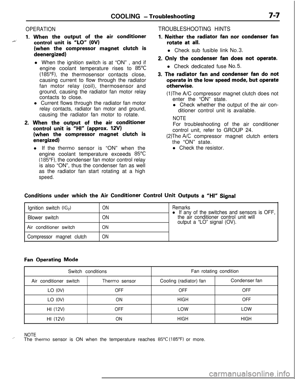
under which the Air Conditioner Control Unit Outputs a “HI” Signal
Ignition switch (IG2)
Blower switchAir conditioner switch
Compressor magnet clutch
ON
ON
ON
ON
Remarksl If any of the switches and sensors is OFF,
the air conditioner control unit will
output a “LO” signal (OV).
Fan Operating Mode
Switch conditions
Air conditioner switch
Therm0 sensor
LO
(OV)OFFLO
(OV)ONHI
(12V)OFFHI
(12V)ONFan rotating condition
Cooling (radiator) fanCondenser fan
OFFOFF
HIGHOFF
LOWLOW
HIGHHIGH
NOTE
_-The therm0 sensor is ON when the temperature reaches 85°C (185°F) or more.
Page 256 of 1216
7-8COOLING - Service Adjustment Procedures
04DooE
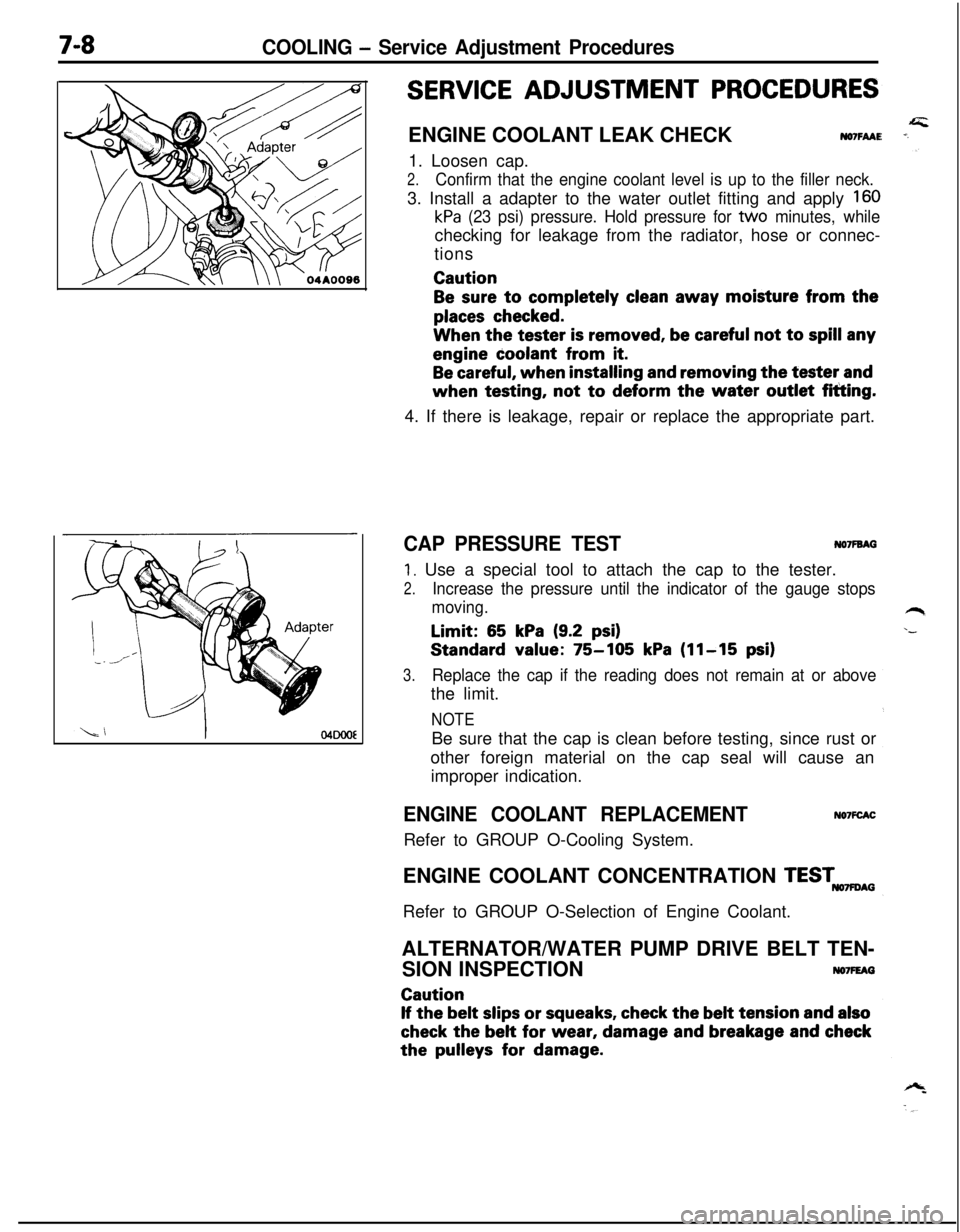
SERVICE ADJUSTMENT PROCEDURESENGINE COOLANT LEAK CHECK
NO7FAAE1. Loosen cap.
2.Confirm that the engine coolant level is up to the filler neck.3. Install a adapter to the water outlet fitting and apply
160
kPa (23 psi) pressure. Hold pressure for tvvo minutes, whilechecking for leakage from the radiator, hose or connec-
tionsCaution
Be sure to completely clean away moisture from the
places checked.When the tester
is removed, be careful not to spill anyengine coolant from
it.
Be careful, when installing and removing the tester andwhen testing, not
to deform the water outlet fitting.
4. If there is leakage, repair or replace the appropriate part.
CAP PRESSURE TESTNO’IFBAG
1. Use a special tool to attach the cap to the tester.
2.Increase the pressure until the indicator of the gauge stops
moving.Limit:
65 kPa (9.2 psi)Standard value:
75-105 kPa (11-15 psi)
3.Replace the cap if the reading does not remain at or abovethe limit.
NOTEBe sure that the cap is clean before testing, since rust or
other foreign material on the cap seal will cause an
improper indication.
ENGINE COOLANT REPLACEMENTRefer to GROUP O-Cooling System.NO’IFCACENGINE COOLANT CONCENTRATION
TESTmAGRefer to GROUP O-Selection of Engine Coolant.
ALTERNATOR/WATER PUMP DRIVE BELT TEN-
SION INSPECTION
NO7FEAGCaution
If the belt slips or squeaks, check the belt tension and also
check the belt for wear, damage and breakage and checkthe
pulleys for damage.
Page 257 of 1216
COOLING - Service Adjustment Procedures7-9Alterhatorpulley
6COOOO9
Spindle
l-
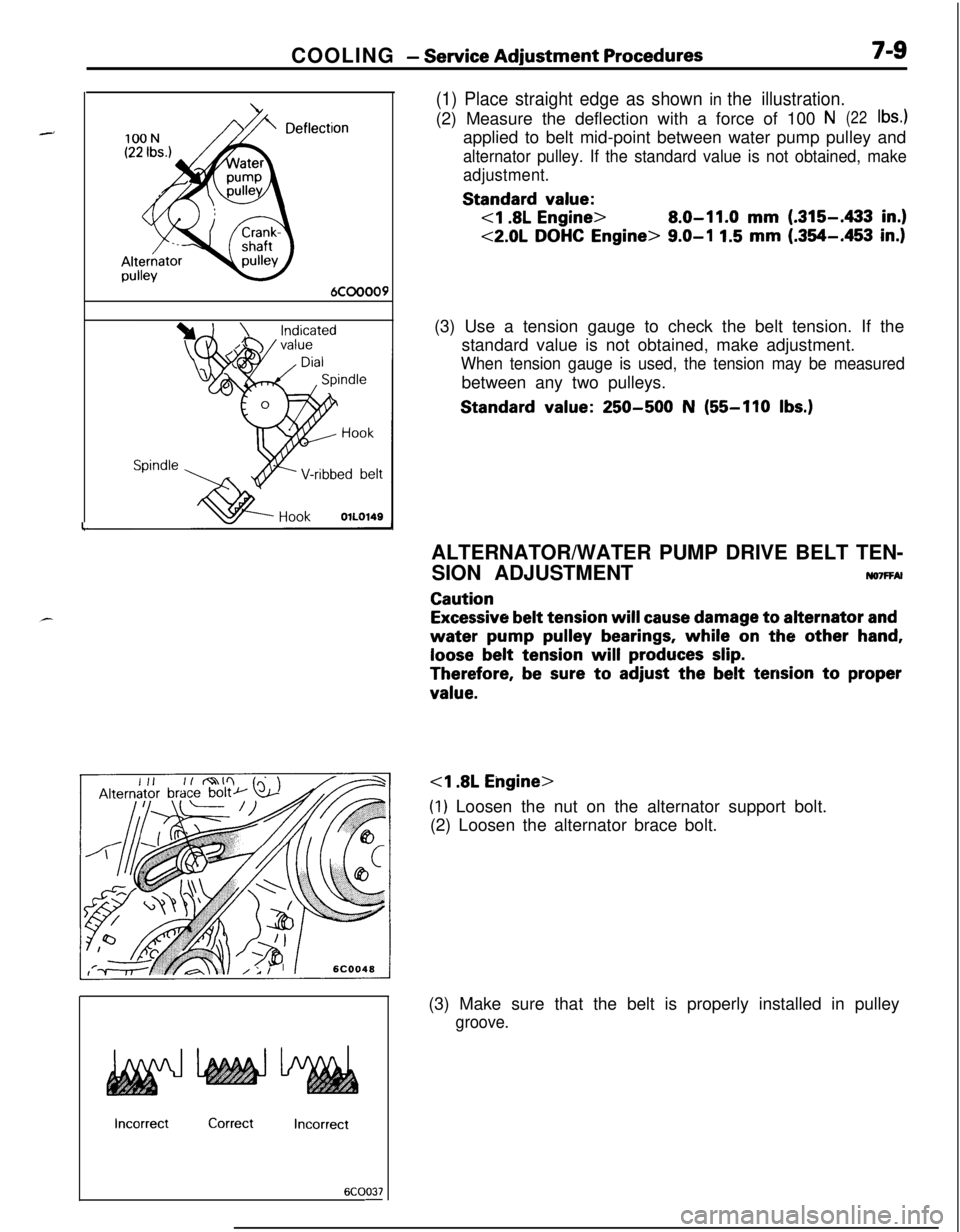
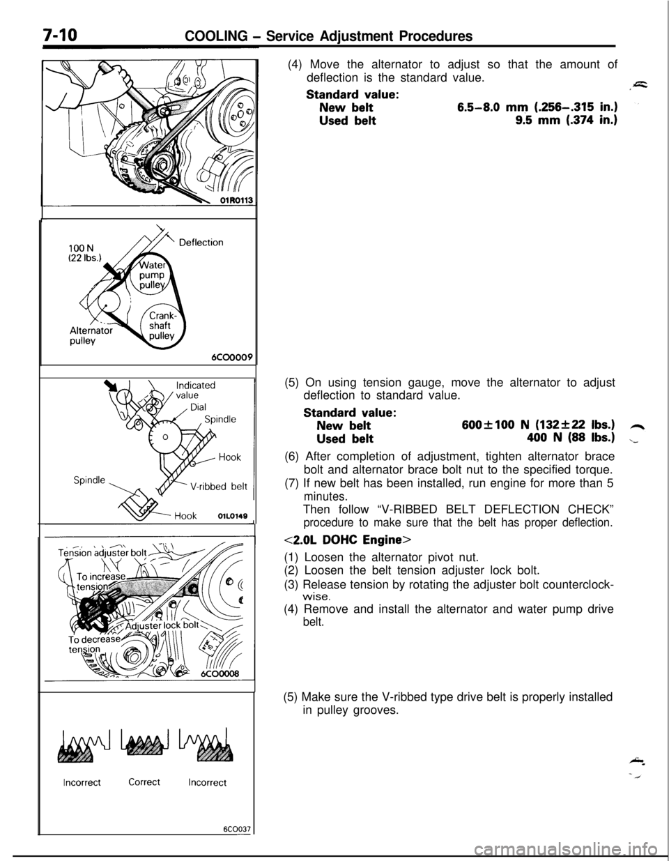
(1) Place straight edge as shown in the illustration.(2) Measure the deflection with a force of 100
N(22lb4applied to belt mid-point between water pump pulley and
alternator pulley. If the standard value is not obtained, make
adjustment.Standard
value:
8.0-11.0 mm (.315-433 in.)
<2.0L DOHC Engine> 9.0-I 1.5 mm (.354-.453 in.)(3) Use a tension gauge to check the belt tension. If the
standard value is not obtained, make adjustment.
When tension gauge is used, the tension may be measuredbetween any two pulleys.Standard
value: 250-500 N (55-110 Ibs.)
IncorrectCorrectIncorrect
6COO37-ALTERNATOR/WATER PUMP DRIVE BELT TEN-
SION ADJUSTMENT
ruo7FFAl
Caution
Excessive belt tension will cause damage to alternator and
water pump pulley bearings, while on the other hand,
loose belt tension will produces slip.
Therefore, be sure to adjust the belt tension to proper
value.
(1) Loosen the nut on the alternator support bolt.
(2) Loosen the alternator brace bolt.
(3) Make sure that the belt is properly installed in pulley
groove.
Page 258 of 1216
COOLING - Service Adjustment Procedures100N
(22 Ibs.)
DeflecAlternator
ypulley
:tion
6COOOO9
Spindle ,
HookOlLO149
IncorrectCorrectIncorrect
6COO37-(4) Move the alternator to adjust so that the amount of
deflection is the standard value.Standard
value:
New belt6.5-8.0 mm (.256-.315 in.)
Used belt9.5 mm (.374 in.)(5) On using tension gauge, move the alternator to adjust
deflection to standard value.Standard
value:
New belt600flOO N (132+22 Ibs.)
Used belt400 N (88 Ibs.)(6) After completion of adjustment, tighten alternator brace
bolt and alternator brace bolt nut to the specified torque.
(7) If new belt has been installed, run engine for more than 5
minutes.Then follow “V-RIBBED BELT DEFLECTION CHECK”
procedure to make sure that the belt has proper deflection.
<2.0L DOHC Engine>
(1) Loosen the alternator pivot nut.
(2) Loosen the belt tension adjuster lock bolt.
(3) Release tension by rotating the adjuster bolt counterclock-
wise.(4) Remove and install the alternator and water pump drive
belt.(5) Make sure the V-ribbed type drive belt is properly installed
in pulley grooves.
Page 260 of 1216
7-12COOLING - Radiator
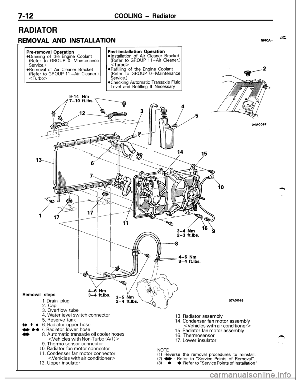
RADIATORPre-removal Operation
@Draining of the Engine Coolant(Refer to GROUP O-Maintenance(Refer to GROUP II-Air Cleaner.)
Service.)
I I
9-14 Nm
_
4-6 Nm3-4 ft.lbs.Removal steps
1 Drain plug2. Cap3. Overflow tube.
4-9 Nm3-4 ft.lbs.
4. Water level switch connector
5. Reserve tank~~ l +6. Radiator upper hose
+e e+ 7. Radiator lower hose
*I)8. Automatic transaxle oil cooler hoses
11. Condenser fan motor connector
04AOOS7
07A0049
13. Radiator assembly14. Condenser fan motor assembly
16. Thermosensor
17. Lower insulator
NOTE(1) Reverse the removal procedures to reinstall.(2) +e : Refer to “Service Points of Removal”.(3) l + : Refer to “Service Points of Installation”
Page 262 of 1216
7-14COOLING - Radiator
A
OFF
ON
h
--- ,
BWatertemperature
16v1100
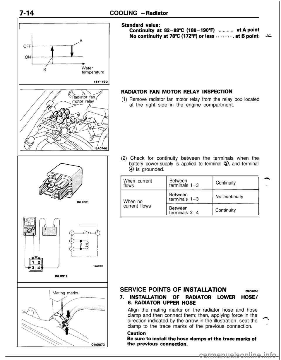
Standard value:Continuity
at 82-88X (180-190°F). . . . . . . . . . .at A pointNo continuity at
78°C (172°F) or less . . . . . . . . at 6 point.r;;;
RADIATOR FAN MOTOR RELAY INSPECTION
(1) Remove radiator fan motor relay from the relay box locatedat the right side in the engine compartment.
16LO312
1Mating marks(2) Check for continuity between the terminals when the
battery power-supply is applied to terminal 0, and terminal
@ is grounded.
When currentBetween
flowsterminals l-3Continuity
When no
current flowsSERVICE POINTS OF
JNSTALLATIONNOMDAF
7. INSTALLATION OF RADIATOR LOWER HOSE/
6. RADIATOR UPPER HOSEAlign the mating marks on the radiator hose and hose
clamp and then connect them; then, applying force in the
direction indicated by the arrow in the illustration, seat the
~
1clamp to the trace marks of the previous connection.Caution
Be sure to install the hose clamps at the trace marks ofthe
previous connection.
Page 264 of 1216
7-16COOLING - Thermostat
INSPECTIONy+w
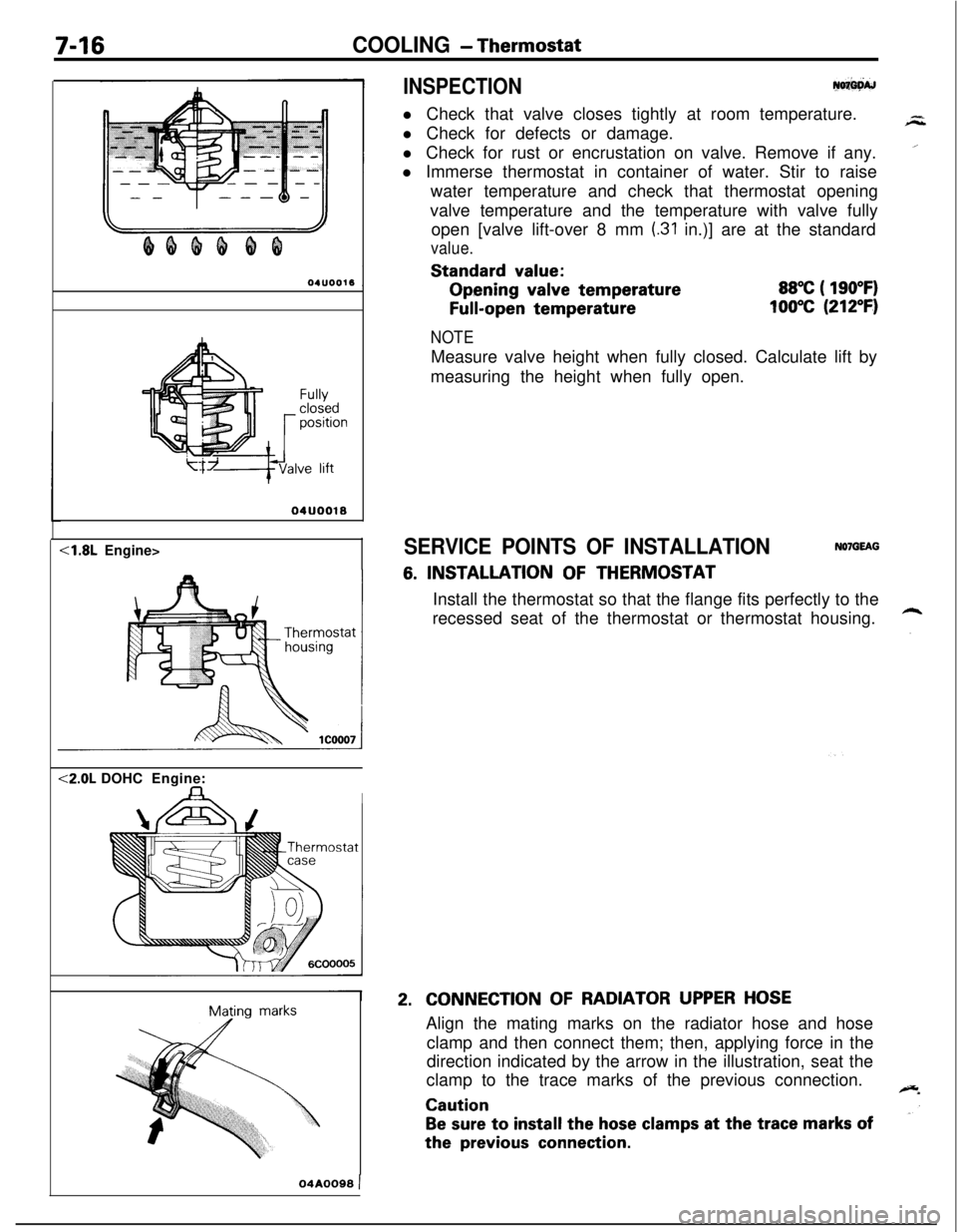
l Check that valve closes tightly at room temperature.
l Check for defects or damage.
l Check for rust or encrustation on valve. Remove if any.
l Immerse thermostat in container of water. Stir to raise
water temperature and check that thermostat opening
valve temperature and the temperature with valve fully
open [valve lift-over 8 mm
(.31 in.)] are at the standard
value.Standard
value:Opening
valve temperature
Full-open temperature
88°C ( 190°F)
100°C (212°F)
Fullyclosedpositionve lift
04UOO18<1.8L Engine><2.0L DOHCEngine:
IMating
marks
NOTEMeasure valve height when fully closed. Calculate lift by
measuring the height when fully open.
SERVICE POINTS OF INSTALLATIONNOlGEAG
6. INSTALLATION OF THERMOSTAT
Install the thermostat so that the flange fits perfectly to the
recessed seat of the thermostat or thermostat housing.
2.CONNECTION OF RADIATOR UPPER HOSEAlign the mating marks on the radiator hose and hose
clamp and then connect them; then, applying force in the
direction indicated by the arrow in the illustration, seat the
clamp to the trace marks of the previous connection.
Caution
Be sure to install the hose clamps at the trace marks ofthe
previous connection.
04A0099 )
Page 267 of 1216
COOLING - Water Pump <1.8L Engine>749SERVICE POINTS OF REMOVAL
NO’IMCAG
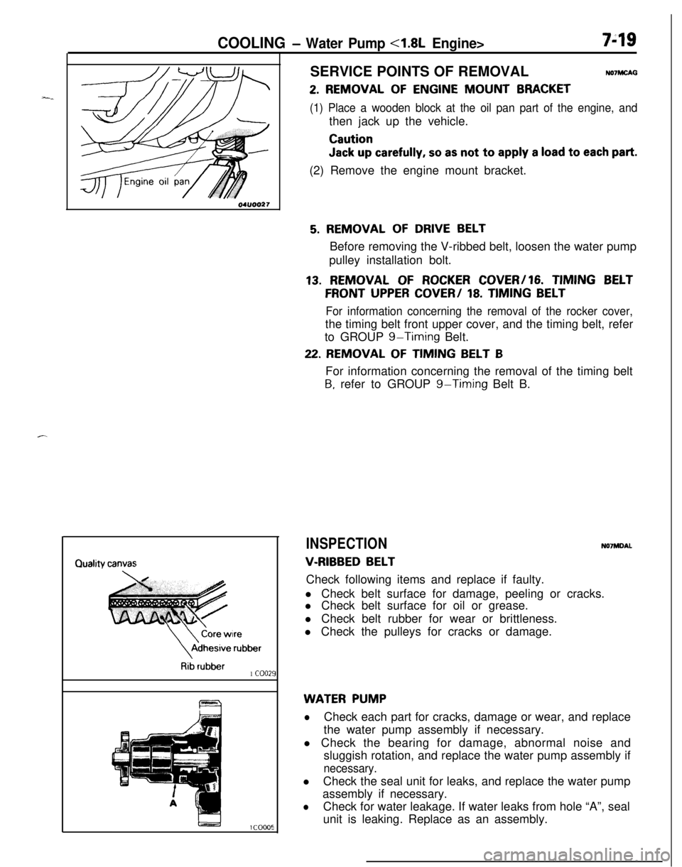
2. REMOVAL OF ENGINE MOUNT BRACKET
(1) Place a wooden block at the oil pan part of the engine, andthen jack up the vehicle.
Caution
Jack up carefully, so as not to apply a load to each part.(2) Remove the engine mount bracket.
\
\
Core wireAdhesive
rubber
Rib rubber1 coo21
5. REMOVAL OF DRIVE BELTBefore removing the V-ribbed belt, loosen the water pump
pulley installation bolt.
13. REMOVAL OF ROCKER COVER/16. TIMING BELT
FRONT UPPER COVER/ 18. TIMING BELT
For information concerning the removal of the rocker cover,the timing belt front upper cover, and the timing belt, refer
to GROUP
g-Timing Belt.
22. REMOVAL OF TIMING BELT BFor information concerning the removal of the timing belt
B, refer to GROUP g-Timing Belt B.
INSPECTIONN07MDAL
V-RIBBED BELTCheck following items and replace if faulty.
l Check belt surface for damage, peeling or cracks.
l Check belt surface for oil or grease.
l Check belt rubber for wear or brittleness.
l Check the pulleys for cracks or damage.
WATER PUMP
lCheck each part for cracks, damage or wear, and replace
the water pump assembly if necessary.
l Check the bearing for damage, abnormal noise and
sluggish rotation, and replace the water pump assembly if
necessary.lCheck the seal unit for leaks, and replace the water pump
assembly if necessary.
lCheck for water leakage. If water leaks from hole “A”, seal
unit is leaking. Replace as an assembly.
Page 268 of 1216
7-20COOLING - Water Pump <1.8L Engine>
aWater pump*<
l-----r,//
O-ringWater
pipe
04ROO24Identification
mark04lJoo25Alternater
brace
404uoo22
J
SERVICE POINTS OF INSTALLATIONN07ME40a
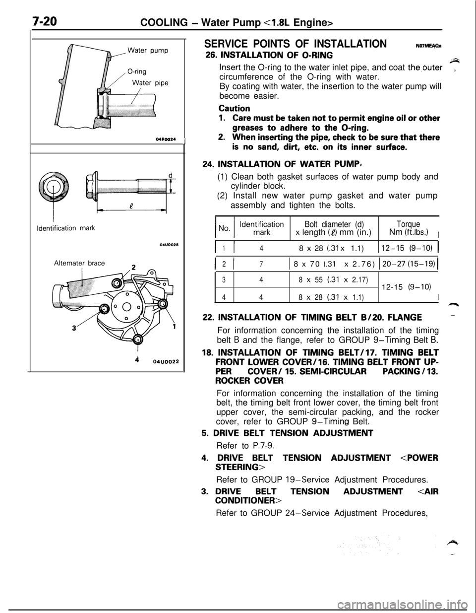
26. INSTALLATION OF O-RINGsInsert the O-ring to the water inlet pipe, and coat the,buter
circumference of the O-ring with water.,
By coating with water, the insertion to the water pump will
become easier.
Caution
1.Care must be taken not to permit engine oil or other
greases to adhere to the O-ring.
2.When inserting the pipe, check to be sure,that there
is no sand, dirt, etc. on its inner surface.
24. INSTALLATION OF WATER PUMP,
(1) Clean both gasket surfaces of water pump body and
cylinder block.
(2) Install new water pump gasket and water pump
assembly and tighten the bolts.
Bolt diameter (d)Torque
x length (e) mm (in.)Nm (ftlbs.)I
I I148 x 28 (.31 x 1.1)112-15 (9-10) 1
I I2
71 8 x 70 (.31 x 2.76) 120-27 (15-19)(
348x55(.31x2.17)12-15(9-10)
448x28(.31x1.1)I
22. INSTALLATION OF TIMING BELT B/20. FLANGE-For information concerning the installation of the timing
belt
B and the flange, refer to GROUP g-Timing Belt B.
18. INSTALLATION OF TIMING BELT/l7. TIMING BELT
FRONT LOWER COVER/lG. TIMING BELT FRONT UP-
PERCOVER/ 15. SEMI-CIRCULARPACKING / 13.
ROCKER COVERFor information concerning the installation of the timing
belt, the timing belt front lower cover, the timing belt front
upper cover, the semi-circular packing, and the rocker
cover, refer to GROUP
g-Timing Belt.
5. DRIVE BELT TENSION ADJUSTMENT
Refer to
P.7-9.
4. DRIVE BELT TENSION ADJUSTMENT
Refer to GROUP
19-Service Adjustment Procedures.
3. DRIVEBELTTENSIONADJUSTMENT
Refer to GROUP
24-Service Adjustment Procedures,