engine oil MITSUBISHI ECLIPSE 1991 Owners Manual
[x] Cancel search | Manufacturer: MITSUBISHI, Model Year: 1991, Model line: ECLIPSE, Model: MITSUBISHI ECLIPSE 1991Pages: 1216, PDF Size: 67.42 MB
Page 371 of 1216
ENGINE <2.0L DOHC Engine> -Camshafts and Camshaft Oil Seals/Oil Pan and Oil Screen9-87
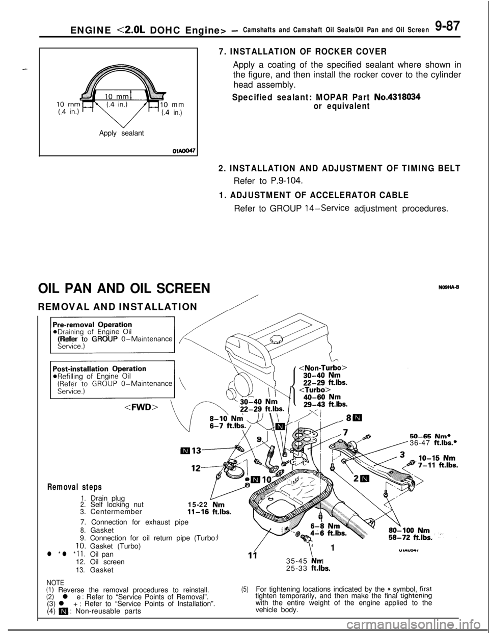
7. INSTALLATION OF ROCKER COVERApply a coating of the specified sealant where shown in
the figure, and then install the rocker cover to the cylinder
head assembly.
Apply sealant
mmin.)
Specified sealant: MOPAR Part No.4318034
or equivalent
olmO47
2. INSTALLATION AND ADJUSTMENT OF TIMING BELTRefer to
P.9-104.
1. ADJUSTMENT OF ACCELERATOR CABLERefer to GROUP 14-Service adjustment procedures.
OIL PAN AND OIL SCREENNO9HA-BREMOVAL AND INSTALLATION
/
/j<&(Refer to GROUP O-Maintenance
\ I/“!18
III13
12-
Removal steps
1.Drain plug2.Self locking nut15-22Nm3.Centermember11-16ft.lbs.7. Connection for exhaust pipe
8.Gasket
9. Connection for oil return pipe (Turbo:IO. Gasket (Turbo)
l * l * 11.Oil pan12.Oil screen
13.Gasket
50-65 Nm*36-47 ft.lbs.*
/117‘1
35-45 NmI25-33 ft.ll3s.
NOTE(I) Reverse the removal procedures to reinstall.(2) l e : Refer to “Service Points of Removal”.
(3) l + : Refer to “Service Points of Installation”.
(4) m : Non-reusable parts
(5)For tightening locations indicated by the * symbol, firsttighten temporarily, and then make the final trghtenrngwith the entire weight of the engine applied to the
vehicle body.
Page 372 of 1216
9-88ENGINE <2.0L DOHC Engine> - Oil Pan and Oil Screen
/
40-60 Nm
30-40 Nm22-29 ft.lbs..
/80-100 Nm458-72
ft.lbs.
70-80 Nm-51-58 ftlbs.15-22 vNm11-16 ft
11b1
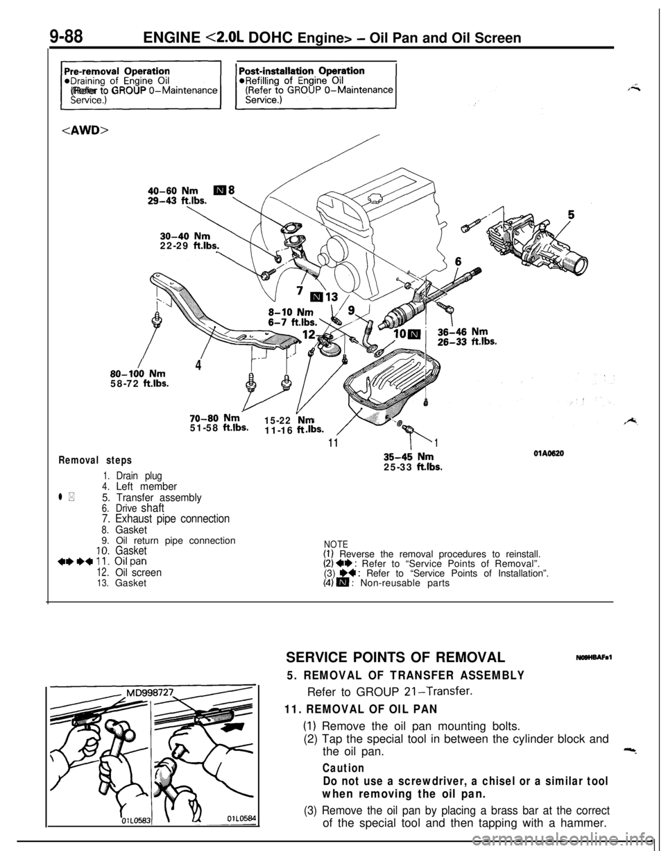
Removal steps
1.Drain plug4.Left member
l *5. Transfer assembly6.Drive shaft
7. Exhaust pipe connection
8.Gasket9. Oil return pipe connection
10.Gasket***+ll. Oilpan
12.Oil screen13.Gasket
35-4; Nm25-33 ftlbs.
OlAO620
NOTE(I) Reverse the removal procedures to reinstall.(2) +I) : Refer to “Service Points of Removal”.
(3) H : Refer to “Service Points of Installation”.(4) m : Non-reusable parts
SERVICE POINTS OF REMOVAL
NOBHBAFal
5. REMOVAL OF TRANSFER ASSEMBLYRefer to GROUP 21-Transfer.
11. REMOVAL OF OIL PAN
(1) Remove the oil pan mounting bolts.
(2) Tap the special tool in between the cylinder block and
the oil pan.
Caution
Do not use a screwdriver, a chisel or a similar tool
when removing the oil pan.
(3) Remove the oil pan by placing a brass bar at the correctof the special tool and then tapping with a hammer.
Page 373 of 1216
ENGINE <2.0L DOHC Engine> - Oil Pan and Oil Screen9-89
Sealant
Grooveole of bolt
0180052
INSPECTION&SHOW
lCheck the oil pan for damage and cracks. Replace if faulty.l Check the oil screen for clogging; damage and cracks.
Replace if faulty.
SERVICE POINTS OF INSTALLATION
NOSHDASa
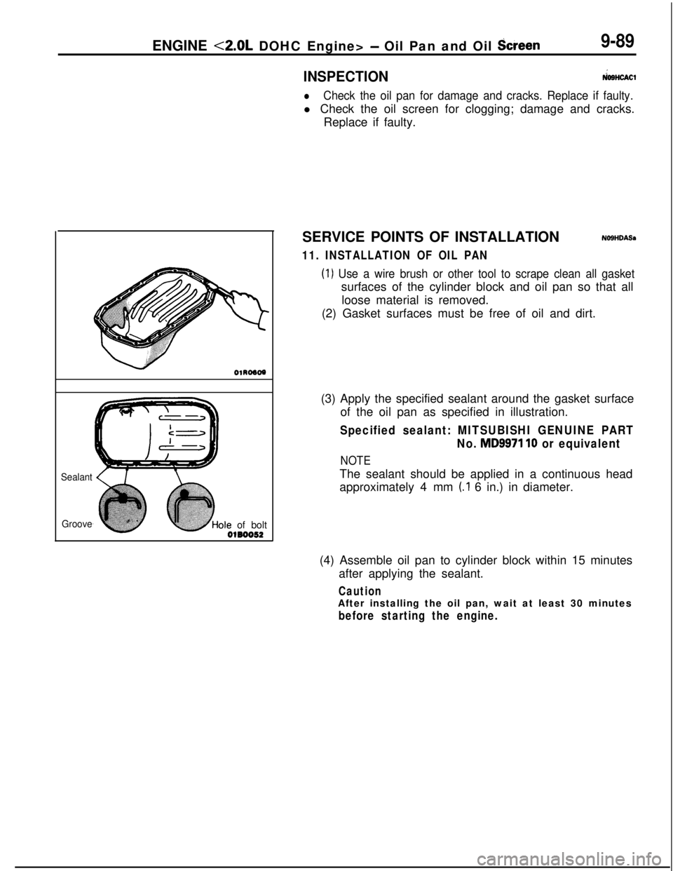
11. INSTALLATION OF OIL PAN
(1) Use a wire brush or other tool to scrape clean all gasketsurfaces of the cylinder block and oil pan so that all
loose material is removed.
(2) Gasket surfaces must be free of oil and dirt.
(3) Apply the specified sealant around the gasket surface
of the oil pan as specified in illustration.
Specified sealant: MITSUBISHI GENUINE PART
No.
MD9971 10 or equivalent
NOTEThe sealant should be applied in a continuous head
approximately 4 mm
(.I 6 in.) in diameter.
(4) Assemble oil pan to cylinder block within 15 minutes
after applying the sealant.
CautionAfter installing the oil pan, wait at least 30 minutes
before starting the engine.
Page 374 of 1216
9-90ENGINE <2.0L DOHC Engine> - Cylinder Head Gasket
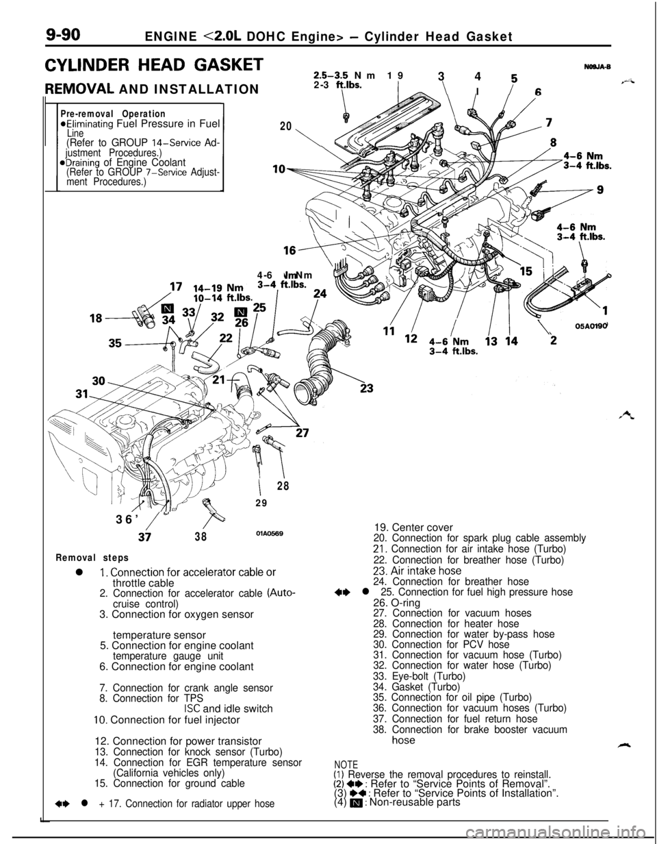
CYLINDER HEAD GASKETNOSJA-S2.5-3.5 Nm 19
3 4 K
REIVIOVAL AND INSTALLATION2-3 ft.lbs.\ I i-6
Pre-removal Operation*Eliminating Fuel Pressure in Fuel20Line1\(Refer to GROUP 14-Service Ad-justment Procedures.)eDraining of Engine Coolant(Refer to GROUP 7-Service Adjust-
ment Procedures.)
,,vs4-6 Nm
’
II28
2936’
/w,=
3i38OlAO5.69
Removal stepsl
1. Connection for accelerator cable orthrottle cable
2. Connection for accelerator cable (Auto-
cruise control)3. Connection for oxygen sensor
temperature sensor
5. Connection for engine coolant
temperature gauge unit6. Connection for engine coolant
7. Connection for crank angle sensor
8. Connection for TPS
ISC and idle switch
10. Connection for fuel injector
12. Connection for power transistor
13. Connection for knock sensor (Turbo)
14. Connection for EGR temperature sensor
(California vehicles only)
15. Connection for ground cable
+e l + 17. Connection for radiator upper hose
/\05ADl9019. Center cover
20. Connection for spark plug cable assembly
21. Connection for air intake hose (Turbo)
22. Connection for breather hose (Turbo)
23.Airintakehose24. Connection for breather hose+e l 25. Connection for fuel high pressure hose26. O-ring
27. Connection for vacuum hoses
28. Connection for heater hose
29. Connection for water by-pass hose
30. Connection for PCV hose
31. Connection for vacuum hose (Turbo)
32. Connection for water hose (Turbo)
33. Eye-bolt (Turbo)
34. Gasket (Turbo)
35. Connection for oil pipe (Turbo)
36. Connection for vacuum hoses (Turbo)
37. Connection for fuel return hose
38. Connection for brake booster vacuum
hoseA
NOTE(1) Reverse the removal procedures to reinstall.(2) +I) : Refer to “Service Points of Removal”.
(3) ~~ : Refer to “Service Points of Installation”.
(4) m : Non-reusable parts
Page 377 of 1216
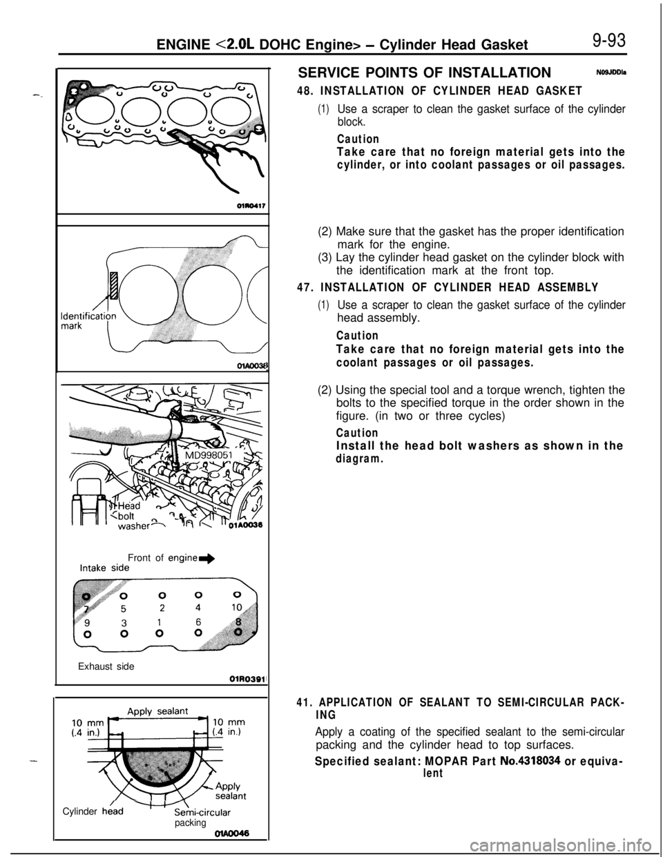
ENGINE <2.0L DOHC Engine> - Cylinder Head Gasket9-93
DlADD3fFront of
engine+Exhaust side
OlR0391Cylinder
he/d-Ani-circularpackingSERVICE POINTS OF INSTALLATIONNOSJDDls
48. INSTALLATION OF CYLINDER HEAD GASKET
(1)Use a scraper to clean the gasket surface of the cylinder
block.
Caution
Take care that no foreign material gets into the
cylinder, or into coolant passages or oil passages.(2) Make sure that the gasket has the proper identification
mark for the engine.
(3) Lay the cylinder head gasket on the cylinder block with
the identification mark at the front top.
47. INSTALLATION OF CYLINDER HEAD ASSEMBLY
(1)Use a scraper to clean the gasket surface of the cylinderhead assembly.
Caution
Take care that no foreign material gets into the
coolant passages or oil passages.(2) Using the special tool and a torque wrench, tighten the
bolts to the specified torque in the order shown in the
figure. (in two or three cycles)
Caution
Install the head bolt washers as shown in the
diagram.
41. APPLICATION OF SEALANT TO SEMI-CIRCULAR PACK-
ING
Apply a coating of the specified sealant to the semi-circularpacking and the cylinder head to top surfaces.
Specified sealant: MOPAR Part No.4318034 or equiva-
lent
Page 379 of 1216
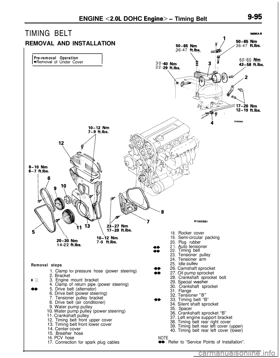
ENGINE <2.0L DOHC Engine> - Timing Belt
TIMING BELT
REMOVAL AND INSTALLATION
I
Pre-removal Operation*Removal of Under Cover
I
50-65 Nm36-47 ft.lbs.
50-65“Nm36-47 ft:lbs.30-60-80
Nm22-20-3\0
Nm14-22 ftlbs.
lo-i2 Nm7-9 ftlbs.
Removal steps
1. Clamp for pressure hose (power steering)2. Bracket
3. Engine mount bracket
4. Clamp of return pipe (power steering)
5. Drive belt (alternator)6. Drive belt (power steering)
7. Tensioner pulley bracket
8. Drive belt (air conditioner)9. Water pump pulley
10. Water pump pulley (power steering)11. Crankshaft pulley12. Timing belt front upper cover13. Timing belt front lower cover
14. Center cover
15. Breather hose16. PCV hose
17. Connection for spark plug cables
l *
4*
NOTE4+ : Refer to “Service Points of Installation”.
WA0581
18.Rocker cover19.Semi-circular packing
20.Plug rubber2 1.Auto tensioner
22.Timing belt
23.Tensioner pulley
24.Tensioner arm
25.Idle oullev26. Camshaft sprocket
27. Oil pump sprocket
28. Crankshaft sprocket bolt
29. Special wastier
30. Crankshaft sprocket
31. Flange32. Tensioner
“B”33. Timing belt “B”
34. Silent shaft sprocket
35. Spacer36. Crankshaft sprocket “B”
37. Left engine support bracket
38. Timing belt rear right cover
39. Timing belt rear left cover (upper)
40. Timing belt rear left cover (lower)
Page 380 of 1216
9-96ENGINE <2.0L DOHC Engine> - Timing Belt
116
/18
Iv- IL 1’11117-9 ftlbs.
\43-49
Nm-_---. . .
30-42 Nm$0
22-30 ftlbs.
\
j2 \ 36
33
15-22 Nm
11-16 ftlbs.
I20-27 Nm\h \
14-20 f&.lbs.110-130 Nm cI,60-94 f
\z/OIAOS83-ama .I~..su--Du Nrnt Ibs .,iJ 36-43 ft.lbs.. .
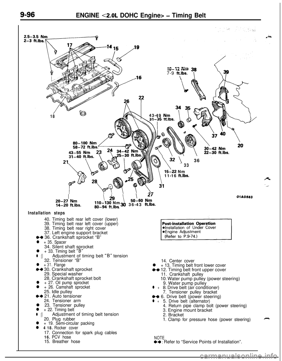
Installation steps
40. Timing belt rear left cover (lower)
39. Timing belt rear left cover (upper)
38. Timing belt rear right cover37. Left engine support bracket
I)+ 36. Crankshaft sprocket “B”
l + 35. Spacer34. Silent shaft sprocket
l + 33. Timing belt “B”
l 4Adjustment of timing belt “B” tension
32. Tensioner “B”
l + 31. Flange++ 30. Crankshaft sprocket
29. Special washer
28. Crankshaft sprocket bolt
l + 27. Oil pump sprocketl + 26. Camshaft sprocket25. Idle pulley
e+ 21. Auto tensioner24. Tensioner arml 23. Tensioner pulleyl + 22. Timing belt
l 4Adjustment of timing belt tension20. Plug rubberl + 19. Semi-circular packingl 4 18. Rocker cover
17. Connection for spark plug cables16. PCV hose15. Breather hose14. Center cover
l + 13. Timing belt front lower covere+ 12. Timing belt front upper cover11. Crankshaft pulley10. Water pump pulley (power steering)
9. Water pump pulley
l +8. Drive belt (air conditioner)7. Tensioner pulley bracketI)+ 6. Drive belt (power steering)l +5. Drive belt (alternator)
4. Return pipe clamp bolt (power steering)3. Engine mount bracket
2. Bracket
1. Clamp for pressure hose (power steering)
NOTE+4 : Refer to “Service Points of Installation”.
Page 381 of 1216
--ENGINE
<2.0L DOHC Engine> - Timing Belt9-97
ExhaustIntake cam-
CrankshaftsproketsprockekOlhw51
1r
SERVICE POINTS OF REMOVAL-a3. REMOVAL OF ENGINE MOUNT BRACKET
(1) With a wooden block placed against the oil pan part of
the engine, jack up the vehicle.
CautionJack up gently, so as not to apply a load to the
various parts.
(2) Remove the engine mount bracket,
5. REMOVAL OF DRIVE BELT (ALTERNATOR)
Before removing the drive belt, loosen the water pump
pulley mounting bolts.
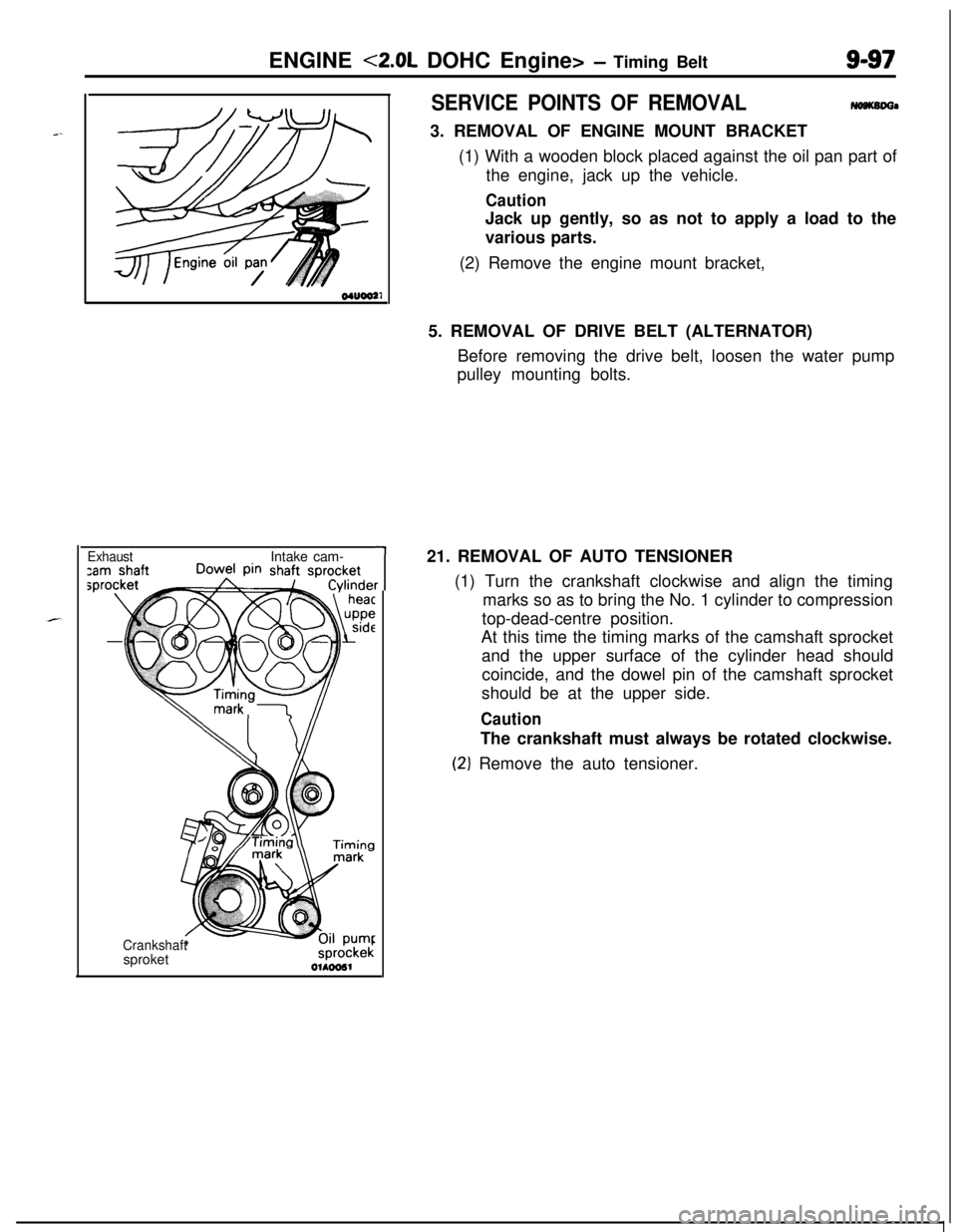
21. REMOVAL OF AUTO TENSIONER
(1) Turn the crankshaft clockwise and align the timing
marks so as to bring the No. 1 cylinder to compression
top-dead-centre position.
At this time the timing marks of the camshaft sprocket
and the upper surface of the cylinder head should
coincide, and the dowel pin of the camshaft sprocket
should be at the upper side.
CautionThe crankshaft must always be rotated clockwise.
(2‘) Remove the auto tensioner.
Page 382 of 1216
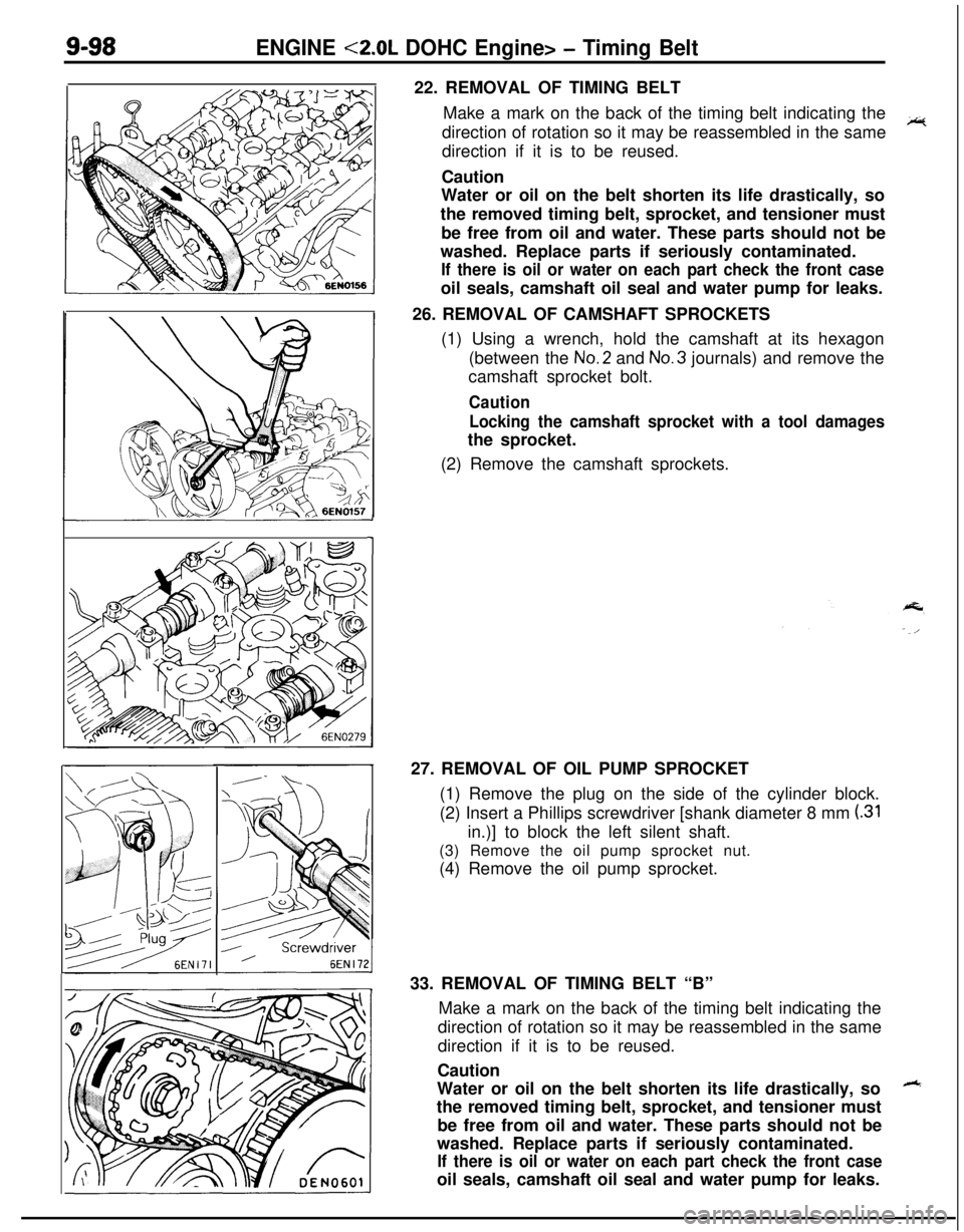
9-98ENGINE <2.0L DOHC Engine> - Timing Belt22. REMOVAL OF TIMING BELT
Make a mark on the back of the timing belt indicating the
direction of rotation so it may be reassembled in the same
~direction if it is to be reused.
Caution
Water or oil on the belt shorten its life drastically, so
the removed timing belt, sprocket, and tensioner must
be free from oil and water. These parts should not be
washed. Replace parts if seriously contaminated.
If there is oil or water on each part check the front caseoil seals, camshaft oil seal and water pump for leaks.
26. REMOVAL OF CAMSHAFT SPROCKETS
(1) Using a wrench, hold the camshaft at its hexagon
(between the No.2 and No.3 journals) and remove the
camshaft sprocket bolt.
Caution
Locking the camshaft sprocket with a tool damagesthe sprocket.
(2) Remove the camshaft sprockets.
127. REMOVAL OF OIL PUMP SPROCKET
(1) Remove the plug on the side of the cylinder block.
(2) Insert a Phillips screwdriver [shank diameter 8 mm
(.31in.)] to block the left silent shaft.
(3) Remove the oil pump sprocket nut.
(4) Remove the oil pump sprocket.
33. REMOVAL OF TIMING BELT “B”
Make a mark on the back of the timing belt indicating the
direction of rotation so it may be reassembled in the same
direction if it is to be reused.
Caution
Water or oil on the belt shorten its life drastically, so
++the removed timing belt, sprocket, and tensioner must
be free from oil and water. These parts should not be
washed. Replace parts if seriously contaminated.
If there is oil or water on each part check the front caseoil seals, camshaft oil seal and water pump for leaks.
Page 385 of 1216
ENGINE <2.0L DOHC Engine> - Timinn Belt
SpacerChahfered
6s
il seal
6EN009Silent shaft
nsprocketI
Timing
markCrankshaft
) ~sprocket “6”Center of
tensioner
pulley
Center of
installation bolt
installation bolt
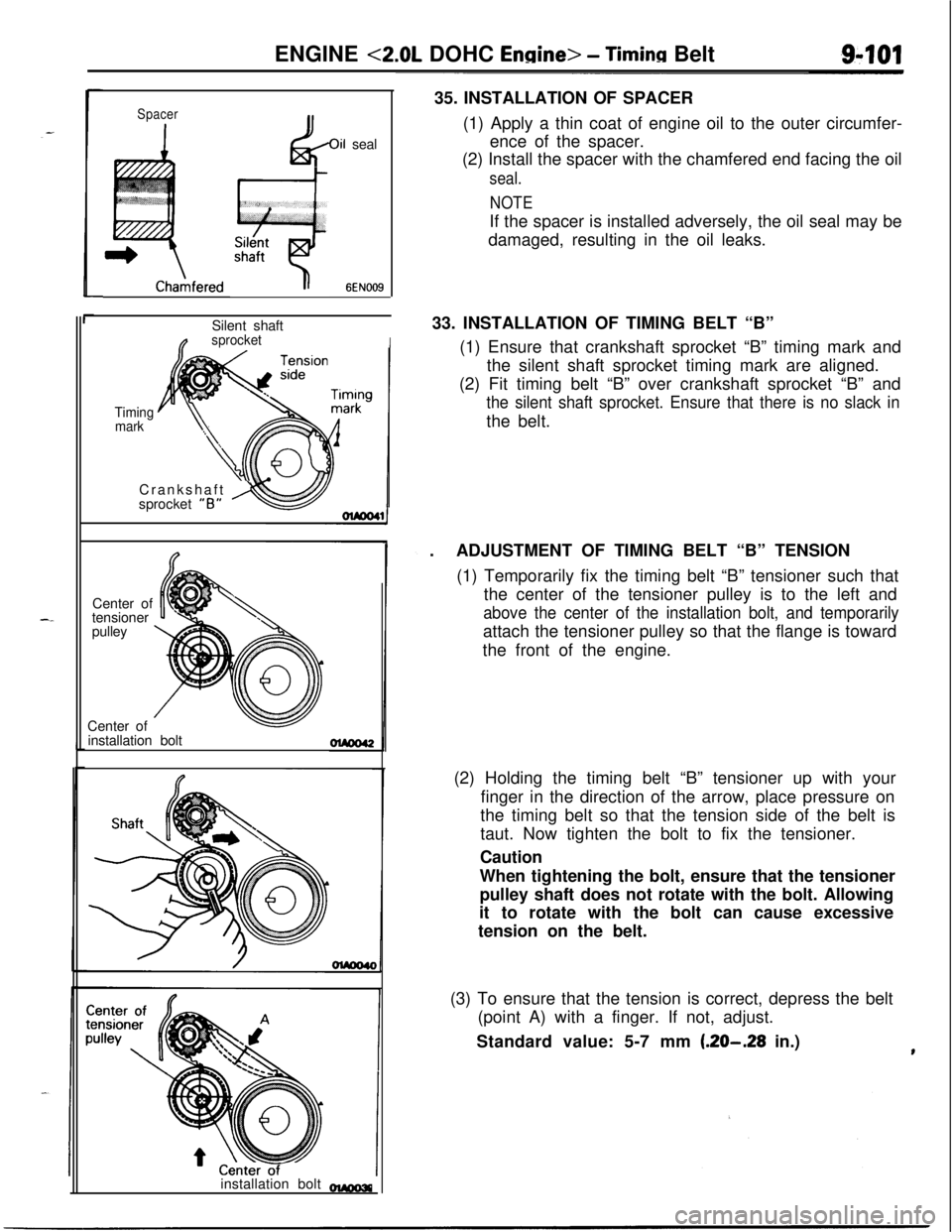
-35. INSTALLATION OF SPACER
(1) Apply a thin coat of engine oil to the outer circumfer-
ence of the spacer.
(2) Install the spacer with the chamfered end facing the oil
seal.
NOTEIf the spacer is installed adversely, the oil seal may be
damaged, resulting in the oil leaks.
33. INSTALLATION OF TIMING BELT “B”
(1) Ensure that crankshaft sprocket “B” timing mark and
the silent shaft sprocket timing mark are aligned.
(2) Fit timing belt “B” over crankshaft sprocket “B” and
the silent shaft sprocket. Ensure that there is no slack inthe belt.
.ADJUSTMENT OF TIMING BELT “B” TENSION
(1) Temporarily fix the timing belt “B” tensioner such that
the center of the tensioner pulley is to the left and
above the center of the installation bolt, and temporarilyattach the tensioner pulley so that the flange is toward
the front of the engine.
(2) Holding the timing belt “B” tensioner up with your
finger in the direction of the arrow, place pressure on
the timing belt so that the tension side of the belt is
taut. Now tighten the bolt to fix the tensioner.
Caution
When tightening the bolt, ensure that the tensioner
pulley shaft does not rotate with the bolt. Allowing
it to rotate with the bolt can cause excessive
tension on the belt.
(3) To ensure that the tension is correct, depress the belt
(point A) with a finger. If not, adjust.
Standard value: 5-7 mm
(.20-.28 in.)