ignition MITSUBISHI ECLIPSE 1991 Service Manual
[x] Cancel search | Manufacturer: MITSUBISHI, Model Year: 1991, Model line: ECLIPSE, Model: MITSUBISHI ECLIPSE 1991Pages: 1216, PDF Size: 67.42 MB
Page 1060 of 1216
23-16BODY - Troubleshooting
OPERATION
Key-reminder warning0 Battery voltage is always supplied, through sub
fusible link No.
@, to the key-reminder switch.0 When the driver’s seat door is opened while the
ignition key is still in the key cylinder, the door
switch is switched ON, electricity flows to sub
fusible link No.
0, the key-reminder switch, the
buzzer, the door switch, and ground, and the
buzzer sounds.
Seat belt warning0 Battery voltage is applied, through fuse No.
0,to the seat belt timer when the ignition key is at
the “ON” position.0 Electricity flows to sub fusible link No. @, the
key-reminder switch, the seat belt warning light,
the seat belt timer, and ground, and the seat beltwarning light illuminates for approx. 6 seconds.0
If the driver does not buckle the seat belt, the seatbelt switch is switched ON, electricity flows to
sub fusible link No. @, the key-reminder switch,the buzzer, the seat belt switch, the seat belt
warning timer, and ground, and the buzzer
sounds for approx. 6 seconds.0 When the driver buckles the seat belt, the seat
belt switch is switched OFF and the buzzer stops.
TROUBLESHOOTING HINTS
Key-reminder warningThe key-reminder warning doesn’t sound.
(1) The seat belt warning function is OK.
l Check the door switch.
(2) The seat belt warning also doesn’t function.0 Check the buzzer.
Seat belt warning1. The seat belt warning doesn’t function.
(1) The seat belt warning light illuminates.0 Check the seat belt switch.
(2) The seat belt warning light also does not
function (but the key-reminder warning
functions normally. 10 Check the seat belt timer.
(3) The seat belt warning light also does not
function (and the key-reminder warning also
does not function).0 Check the key-reminder switch.
2.The buzzer doesn’t stop even though the driver’s
seat belt has been buckled.0 Check the seat belt switch.
3.The seat belt warning light doesn’t illuminate (but
the buzzer sounds).l Check the light bulb.
’ I
Page 1064 of 1216
23-20BODY - Troubleshooting
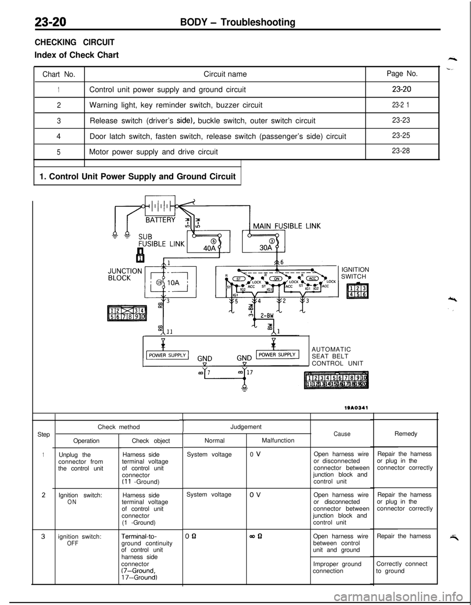
CHECKING CIRCUITIndex of Check Chart
Chart No.Circuit name
1Control unit power supply and ground circuit
2Warning light, key reminder switch, buzzer circuit
3Release switch (driver’s side), buckle switch, outer switch circuit
4Door latch switch, fasten switch, release switch (passenger’s side) circuit
5Motor power supply and drive circuit
1. Control Unit Power Supply and Ground Circuit
Page No.
23-20
23-2 1
23-23
23-25
23-28IGNITION
SWITCH
,\--AUTOMATIC
SEAT BELT
CONTROL UNIT
Step
1
2
3Check method
Operation
Unplug the
connector from
the control unit
Ignition switch:
ONignition switch:
OFFCheck object
Harness side
terminal voltage
of control unit
connector
(I 1 -Ground)
Harness side
terminal voltage
of control unit
connector
(1 -Ground)
Terminal-to-ground continuity
of control unit
harness side
connector
(7-Ground,17-Ground)
TJudgement
NormalMalfunction
System voltage0 VCauseOpen harness wire
or disconnected
connector between
junction block and
control unitRemedy
Repair the harness
or plug in the
connector correctly
System voltage
0 V
Open harness wire
or disconnected
connector between
junction block and
control unitRepair the harness
or plug in the
connector correctly
00allOpen harness wire
between control
unit and groundRepair the harness
Improper groundCorrectly connect
connectionto ground
Page 1065 of 1216
BODY - Troubleshooting23-21
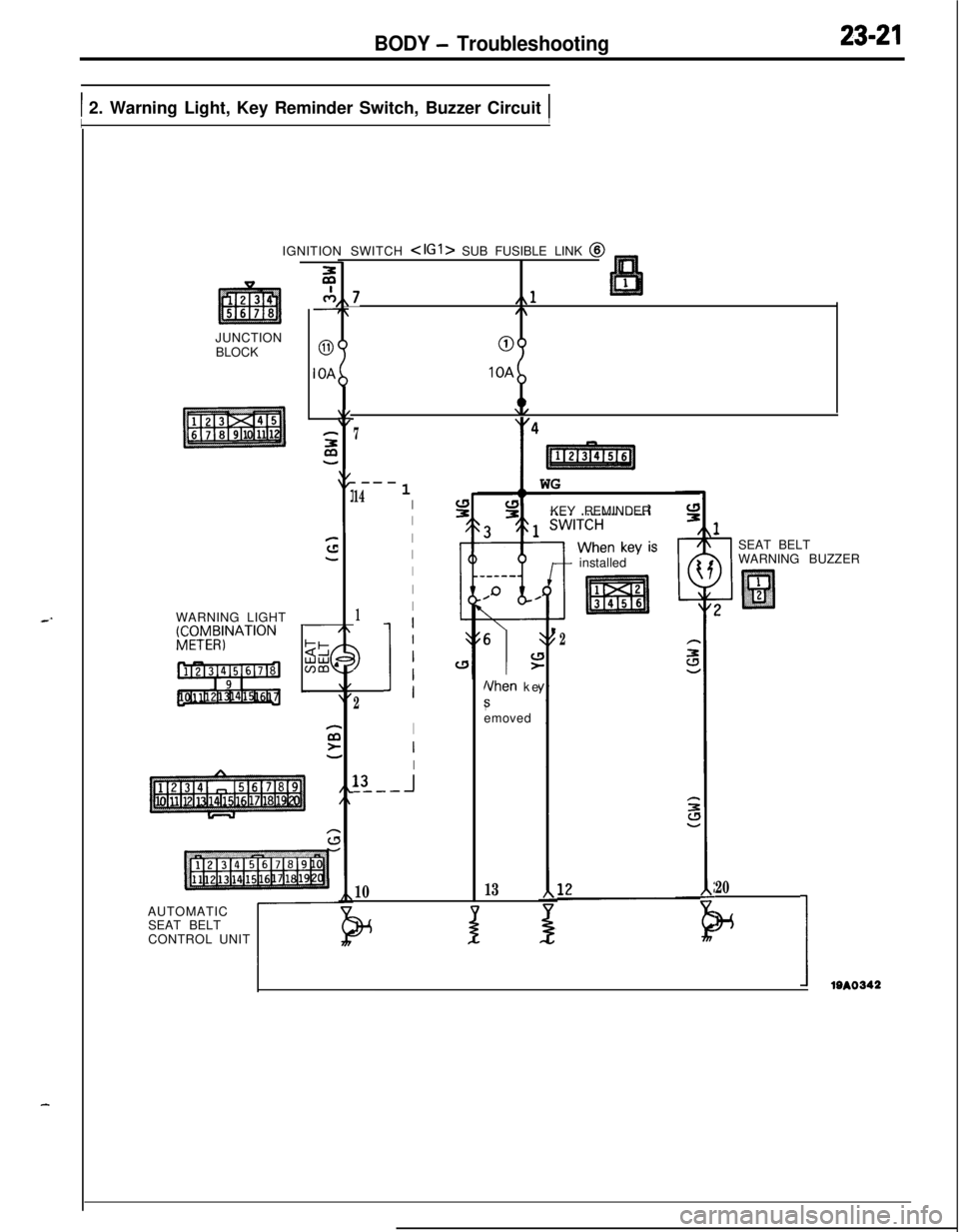
1 2. Warning Light, Key Reminder Switch, Buzzer Circuit 1IIJUNCTION
BLOCK
WARNING LIGHT
gCTy4;NATION
c-7,,7L,,l7,/\
00IOA
IOA
2:y47
.---
141I
I
I
I
I
I
1I
3
2
11
I
I
I13
-I_---
10IGNITION SWITCH
SEAT BELT
CONTROL UNIT
t
11 WG
KEY REMINDER
6
\IL!>
Nhen ke
8emoved
13
+ installed
J
2
1SEAT BELT
WARNING BUZZER
20
w
IIem
Page 1066 of 1216
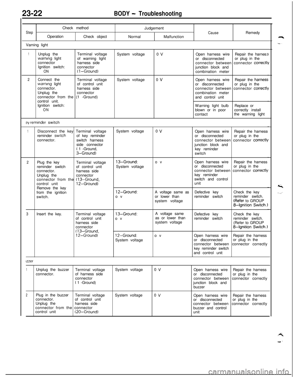
23-22BODY - TroubleshootingCheck method
StepOperation
Check object
Varning lightJudgementCauseRemedy
NormalMalfunction
1Unplug theTerminal voltagewarnrng light
of warning light
connector
harness side
Ignition switch:
connector
ON(I-Ground)
2Connect the
Terminal voltagewarnrng light
of control unit
connector.
harness side
Unplug theconnector
connector from the (1 -Ground)
control unit.
Ignition switch:
ON
ey reminder switchSystem voltage
System voltage0 V
0 VOpen harness wireRepair the harnes:
or disconnectedor plug in the
connector between connector
correct1junction block and
combination meter
Open harness wireRepair the harries:
or disconnectedor plug in the
connector between connector
correctl!combination meter
and control unit
Warning light bulbReplace or
blown or in poorcorrectly install
contactthe warning light
1Disconnect the key Terminal voltageSystem voltage0 VOpen harness wireRepair the harness
reminder switchof key reminder
or disconnectedor plug in the
connector.
switch harnessconnector between connector
correct11side connector
junction block and
t 1 -Ground,
key reminderS-Ground)switch
2Plug the key
Terminal voltage13-Ground:ovOpen harness wireRepair the harness
reminder switchof control unitSystem voltageor disconnectedor plug in the
connector.
harness sideconnector between connector
correct11Unplug theconnectorkey reminder
connector from the
(13-Ground,switch and control
control unit12-Ground)unit
Remove the key
from the ignition
12-Ground:A voltage same asDefective keyCheck the key
switch.ovor lower thanreminder switchreminder switch.
system voltage(Refer to GROUP
84gnition Switch.1
3Insert the key.Terminal voltage
13-Ground:A voltage same
as or lower thanDefective keyCheck the key
of control unit
ovreminder switchreminder switch.
harness sidesystem voltage
(Refer to GROUP
connector
84gnition Switch.1(13-Ground,12-Ground)12-Ground:ovOpen harness wireRepair the harness
System voltageor disconnectedor plug in the
connector between connector correctly
key reminder switch
and control unit
lzzer
1Unplug the buzzer
Terminal voltageSystem voltage0 VOpen harness wireRepair the harness
connector.of harness side
or disconnectedor plug in the
connector
connector between connector correctly
t 1 -Ground)
junction block and
buzzer
2Plug in the buzzer
Terminal voltageSystem voltage0 VOpen harness wireRepair the harness
connector.
of control unit
or disconnectedor plug in the
Unplug the
harness side
connector between connector correctly
connector from the connector
buzzer and control
control unit
(20-Ground)unit
Page 1151 of 1216
HEATERS AND AIR CONDITIONING - Troubleshootinq
-.
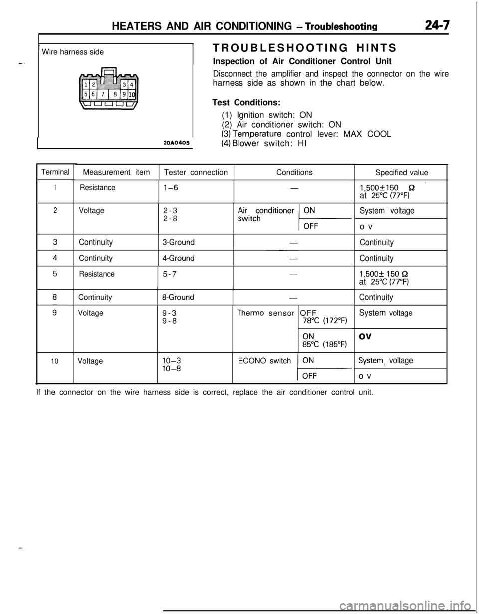
’ Wire harness sideTROUBLESHOOTING HINTS
Inspection of Air Conditioner Control Unit
Disconnect the amplifier and inspect the connector on the wireharness side as shown in the chart below.
Test Conditions:
(1) Ignition switch: ON
(2) Air conditioner switch: ON
(3) Temoerature control lever: MAX COOL2OAO405
(4j Bloier switch: HI
TerminalMeasurement item
Tester connectionConditions
Specified value
1Resistancel-6-1,500f150 sz ’at 25°C (77°F)
2
10
Voltage2-3
2-8Airtcchonditioner
ContinuityContinuity3-Ground
4-Ground
Resistance5-7
-ContinuityII
8-Ground-
Voltage9-3
9-8Therm0 sensor OFF78°C (172°F)
:5k (185°F)
Voltage10-3ECONO switch
10-8
System voltageov
Continuity
Continuity1,500+
150 s-2at 25°C (77’F)
Continuity
System voltageov
System? voltageov
If the connector on the wire harness side is correct, replace the air conditioner control unit.
Page 1216 of 1216
25-20Exhaust Gas Recirculation (EGR) System/EMISSION CONTROL SYSTEMS - ‘catalytic Converter(5) Measure the resistance between the terminals
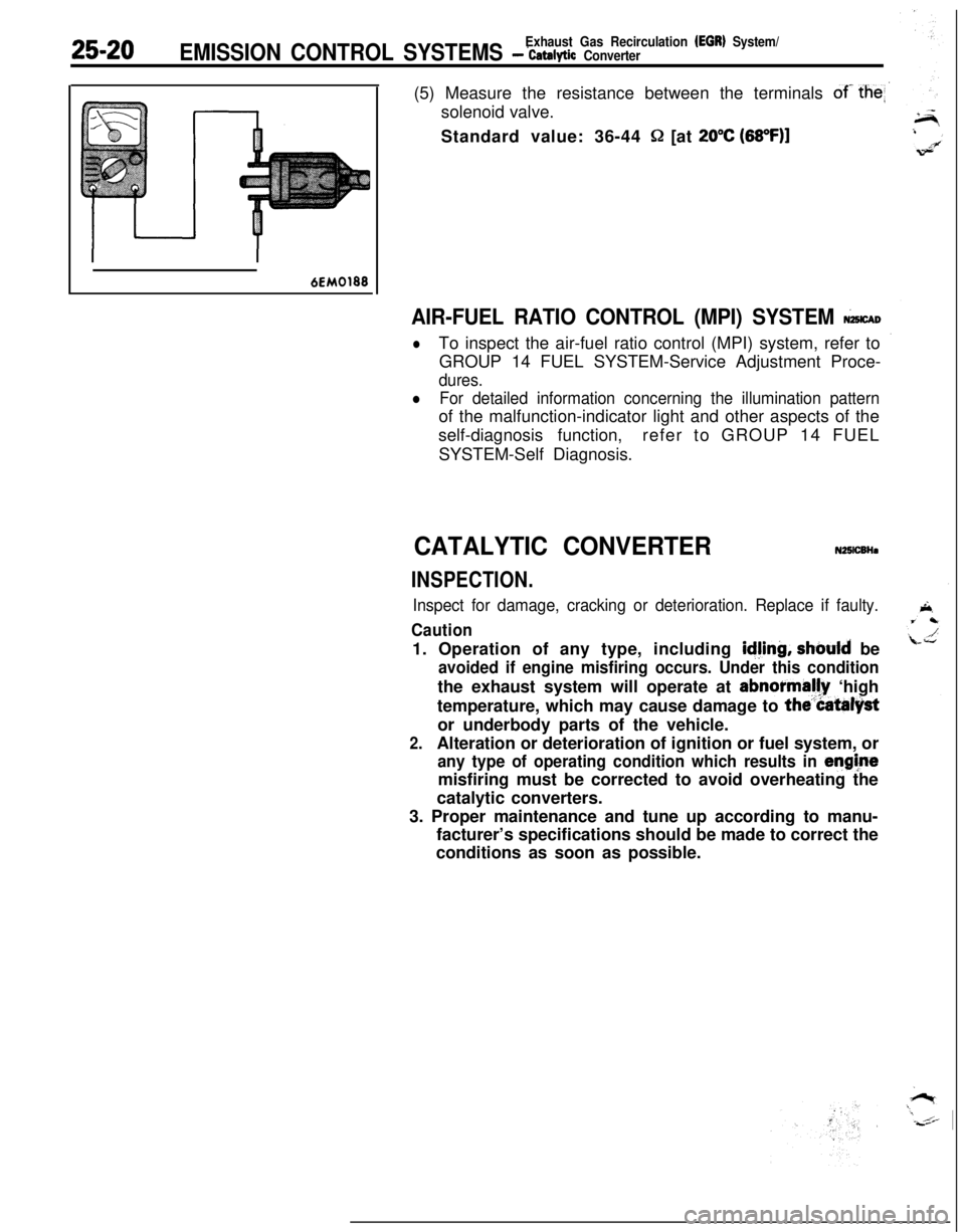
of- the
Q [at 20°C (68OF)l
6EM0188
AIR-FUEL RATIO CONTROL (MPI) SYSTEM &CAD
lTo inspect the air-fuel ratio control (MPI) system, refer to
GROUP 14 FUEL SYSTEM-Service Adjustment Proce-
dures.
lFor detailed information concerning the illumination patternof the malfunction-indicator light and other aspects of the
self-diagnosis function,refer to GROUP 14 FUEL
SYSTEM-Self Diagnosis.
CATALYTIC CONVERTERN25lCBHa
INSPECTION.
Inspect for damage, cracking or deterioration. Replace if faulty.
Caution1. Operation of any type, including
idjing, should be
avoided if engine misfiring occurs. Under this conditionthe exhaust system will operate at abnormally ‘high
temperature, which may cause damage to
the”Catalystor underbody parts of the vehicle.
2.Alteration or deterioration of ignition or fuel system, or
any type of operating condition which results in enghtemisfiring must be corrected to avoid overheating the
catalytic converters.
3. Proper maintenance and tune up according to manu-
facturer’s specifications should be made to correct the
conditions as soon as possible.