ignition MITSUBISHI ECLIPSE 1991 Owners Manual
[x] Cancel search | Manufacturer: MITSUBISHI, Model Year: 1991, Model line: ECLIPSE, Model: MITSUBISHI ECLIPSE 1991Pages: 1216, PDF Size: 67.42 MB
Page 874 of 1216
21480AUTOMATIC TRANSAXLE - Troubleshootina
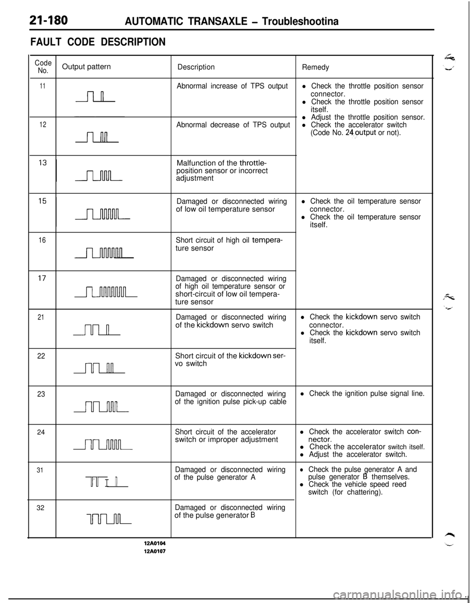
FAULT CODE DESCRIPTION
Code
No.Output patternDescription
Remedy
11Abnormal increase of TPS outputl Check the throttle position sensor
nconnector.
l Check the throttle position sensoritself.
12l Adjust the throttle position sensor.
Abnormal decrease of TPS outputl Check the accelerator switch
(Code No. 24output
or not).Malfunction of the throttle-
position sensor or incorrect
adjustment
Damaged or disconnected wiringl Check the oil temperature sensorof low oil temperature sensor
connector.
l Check the oil temperature sensoritself.
16Short circuit of high oil tempera-ture sensor
Damaged or disconnected wiring
of high oil temperature sensor orshort-circuit of low oil tempera-
ture sensor
21
n
Damaged or disconnected wiringl Check the kickdown servo switchof the kickdown servo switch
connector.l Check the kickdown servo switch
itself.
22
nnShort circuit of the kickdown
ser-vo switch
23Damaged or disconnected wiringl Check the ignition pulse signal line.
of the ignition pulse pick-up cable24
Short circuit of the acceleratorswitch or improper adjustmentl Check the accelerator switch con-
nectar.l Check the accelerator switch itself.
l Adjust the accelerator switch.
31
u’u I n
Damaged or disconnected wiring
of the pulse generator AlCheck the pulse generator A and
pulse generator B themselves.l Check the vehicle speed reed
switch (for chattering).32
Damaged or disconnected wiring
uuLnJ-l-of the pulse generator B
12A0104
12A0107
Page 877 of 1216
AUTOMATIC TRANSAXLE - Troubleshooting214%3
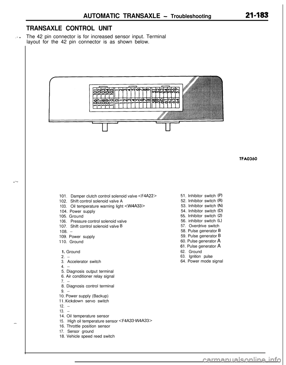
TRANSAXLE CONTROL UNIT
-‘” .The 42 pin connector is for increased sensor input. Terminal
layout for the 42 pin connector is as shown below.TFA0360
101.Damper clutch control solenoid valve
102.Shift control solenoid valve A
103.Oil temperature warning light
105. Ground
106.Pressure control solenoid valve
107.Shift control solenoid valve B108.
-
109. Power supply
110. Ground
1. GroundL.
-
3.Accelerator switch
4.-5. Diagnosis output terminal
6. Air conditioner relay signal
7.-8. Diagnosis control terminal
9.-
IO. Power supply (Backup)
11. Kickdown servo switch
12.-
13.-14. Oil temperature sensor
15.High oil temperature sensor
16. Throttle position sensor
17.Sensor ground18. Vehicle speed reed switch
51. Inhibitor switch (PI52. Inhibitor switch
(8)53. Inhibitor switch
(N)54. Inhibitor switch
(D)
55. Inhibitor switch (2)56. inhibitor switch
(L)
57.Overdrive switch
58. Pulse generator
B59. Pulse generator
B60. Pulse generator A
61. Pulse generator A
62.Ground63.Ignition pulse64. Power mode signal
Page 896 of 1216
21-202AUTOMATIC TRANSAXLE - Troubleshooting
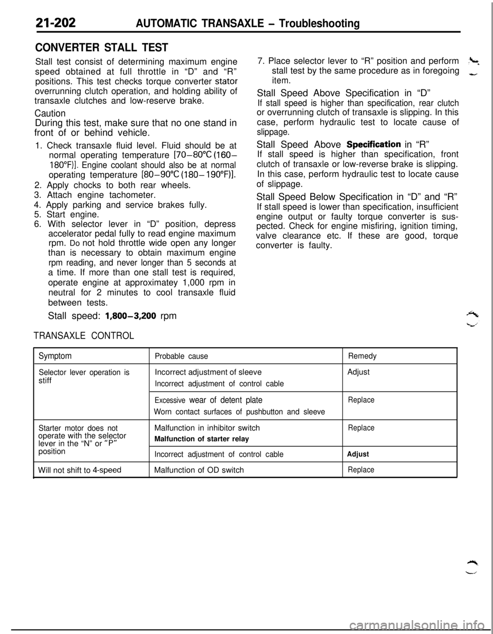
CONVERTER STALL TESTStall test consist of determining maximum engine
speed obtained at full throttle in “D” and “R”
positions. This test checks torque converter stator
overrunning clutch operation, and holding ability of
transaxle clutches and low-reserve brake.
CautionDuring this test, make sure that no one stand in
front of or behind vehicle.
1. Check transaxle fluid level. Fluid should be at
normal operating temperature
[70-80°C (160-
18O”F)]. Engine coolant should also be at normaloperating temperature
[80-90°C (180- 19O”F)l.2. Apply chocks to both rear wheels.
3. Attach engine tachometer.
4. Apply parking and service brakes fully.
5. Start engine.
6. With selector lever in “D” position, depress
accelerator pedal fully to read engine maximum
rpm. Do not hold throttle wide open any longer
than is necessary to obtain maximum engine
rpm reading, and never longer than 5 seconds ata time. If more than one stall test is required,
operate engine at approximatey 1,000 rpm in
neutral for 2 minutes to cool transaxle fluid
between tests.
Stall speed:
1,800-3,200 rpm
TRANSAXLE CONTROL7. Place selector lever to “R” position and perform
?+stall test by the same procedure as in foregoing
-,
item.Stall Speed Above Specification in “D”
If stall speed is higher than specification, rear clutchor overrunning clutch of transaxle is slipping. In this
case, perform hydraulic test to locate cause of
slippage.Stall Speed Above Specifjcation in “R”
If stall speed is higher than specification, front
clutch of transaxle or low-reverse brake is slipping.
In this case, perform hydraulic test to locate cause
of slippage.
Stall Speed Below Specification in “D” and “R”
If stall speed is lower than specification, insufficient
engine output or faulty torque converter is sus-
pected. Check for engine misfiring, ignition timing,
valve clearance etc. If these are good, torque
converter is faulty.
Symptom
Selector lever operation isstiff
Probable causeIncorrect adjustment of sleeve
Incorrect adjustment of control cable
Excessive wear of detent plate
Worn contact surfaces of pushbutton and sleeveRemedyAdjust
Replace
Starter motor does notoperate with the selector
lever in the “N” or
“P”position
Will not shift to
4-speedMalfunction in inhibitor switch
Malfunction of starter relay
Incorrect adjustment of control cableMalfunction of OD switch
Replace
Adjust
Replace
Page 898 of 1216
21-204AUTOMATIC TRANSAXLE - Troubleshooting
c;_----__---___-.
IGNITIONSWITCH(IG2)0
?
3E-7r
0
1UA
\IEjC-53mJ
ca (LB)
POWER/
ECONOMY
;$;;E OVER "r-
D-19A, .
12l!i3Fl3453$
,F
IGHT
3 19 ~lo~ll~l2~la~lq1qls
E
A/T SELECTOR
LEVER POSITION
ILLUMINATIONLIGHT
WITHOUTAU;iUi~;UISE
hf---
II
sP5 11
LIEI
AUTO-
CRUISE
CONTROL
UNIT
Y
-t
______--___---__--------
4
gF
C-61 57_______-__-----_---_-----
J/B
Remark**Mark indicates the oPtional wiringFEI~~I;S for auto-cruise control
Page 904 of 1216
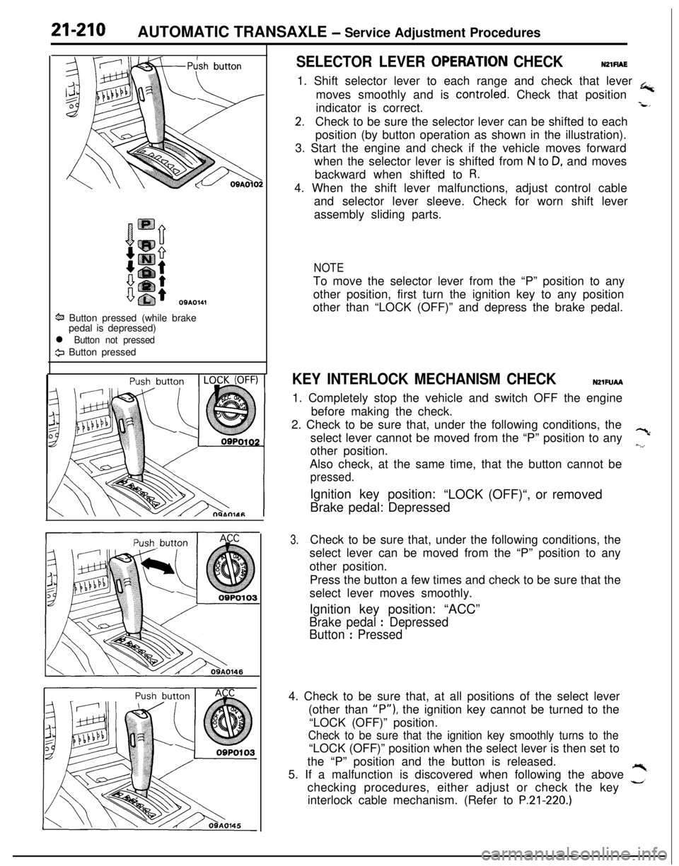
21-210AUTOMATIC TRANSAXLE - Service Adjustment Procedures
OSA0141
ti Button pressed (while brake
pedal is depressed)
l Button not pressed
9 Button pressed
SELECTOR LEVER OPERATlON CHECKNZlFlAE1. Shift selector lever to each range and check that lever
+moves smoothly and is controled. Check that position
indicator is correct.
-L*
2.Check to be sure the selector lever can be shifted to each
position (by button operation as shown in the illustration).
3. Start the engine and check if the vehicle moves forward
when the selector lever is shifted from
N to D, and moves
backward when shifted to
R.4. When the shift lever malfunctions, adjust control cable
and selector lever sleeve. Check for worn shift lever
assembly sliding parts.
NOTETo move the selector lever from the “P” position to any
other position, first turn the ignition key to any position
other than “LOCK (OFF)” and depress the brake pedal.
KEY INTERLOCK MECHANISM CHECKNZlFUAA1. Completely stop the vehicle and switch OFF the engine
before making the check.
2. Check to be sure that, under the following conditions, the
select lever cannot be moved from the “P” position to any
?cother position.
~.‘,Also check, at the same time, that the button cannot be
pressed.Ignition key position:
“LOCK (OFF)“, or removed
Brake pedal: Depressed
3.Check to be sure that, under the following conditions, the
select lever can be moved from the “P” position to any
other position.
Press the button a few times and check to be sure that the
select lever moves smoothly.
Ignition key position: “ACC”
Brake pedal : Depressed
Button
: Pressed4. Check to be sure that, at all positions of the select lever
(other than
“P”), the ignition key cannot be turned to the
“LOCK (OFF)” position.
Check to be sure that the ignition key smoothly turns to the“LOCK (OFF)” position when the select lever is then set to
the “P” position and the button is released.
5. If a malfunction is discovered when following the above
,”checking procedures, either adjust or check the key
interlock cable mechanism. (Refer to
P.21-220.)
Page 905 of 1216
AUTOMATIC TRANSAXLE - Service Adjustment Procedures21-21109A0146
OQMOO45
control lever
control lever
5 mm
Section A-A
(2 in.)Manual
controllever
Switch body
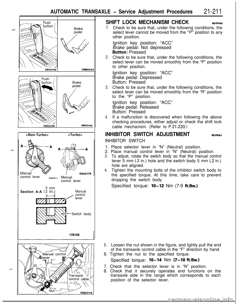
SHIFT LOCK MECHANISM CHECKN21FVAA
1.
2.
3.
4.Check to be sure that, under the following conditions, the
select lever cannot be moved from the
“P” position to any
other position.
Ignition key position: “ACC”
Brake pedal: Not depressedButton: Pressed
Check to be sure that, under the following conditions, the
select lever can be moved smoothly from the “P” position
to other position.
Ignition key position: “ACC”
Brake pedal: Depressed
Button: Pressed
Check to be sure that, under the following conditions, the
select lever can be moved smoothly from the “R” position
to the “P” position.
Ignition key position: “ACC”
Brake pedal: Released
Button: Pressed
If a malfunction is discovered when following the above
checking procedures, either adjust or check the shift lock
cable mechanism. (Refer to
P.21-220.)
INHIBITOR SWITCH ADJUSTMENTNZlFKAJ
INHIBITOR SWITCH1. Place selector lever in “N” (Neutral) position.
2. Place manual control lever in “N” (Neutral) position.
3.To adjust, rotate the switch body so that the manual controllever 5 mm
(2 in.) hole and the switch body 5 mm (.2 in.)
hole are aligned.
4.Tighten the mounting bolts of the inhibitor switch body to
the specified torque. At this time, take care to prevent
dropping the switch body.
Specified torque:
lo-12 Nm (7-9 ftlbs.)
5.Loosen the nut shown in the figure, and lightly pull the end
of the transaxle control cable in the “F” direction by hand.
6. Tighten the nut to the specified torque.
Specified torque:
IO-14 Nm (7-10 ftlbs.)7. Check that the selector lever is in “N” position.
8. Check that it securely operates and functions on the
transaxle side in the range which corresponds to each
position of the selector lever.
Page 914 of 1216
AUTOMATIC TRANSAXLE - Transaxle Control
:lemotJnt
\\ \09R0058
09AO143
/’
\
’ CoverCoverKey interlock cableOSA0125
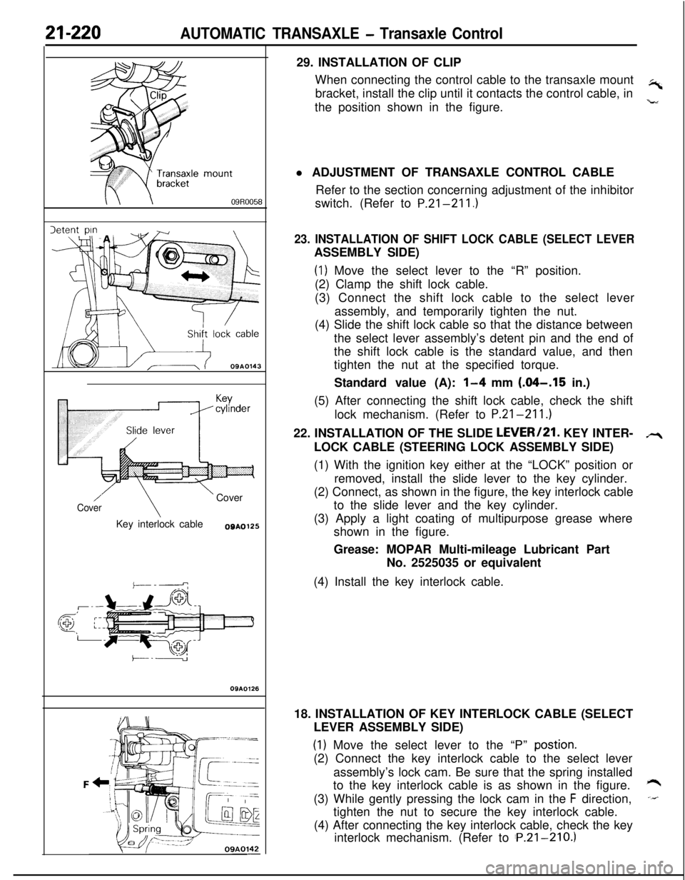
OSAO12629. INSTALLATION OF CLIP
When connecting the control cable to the transaxle mount
,-bracket, install the clip until it contacts the control cable, in
the position shown in the figure.
,”l ADJUSTMENT OF TRANSAXLE CONTROL CABLE
Refer to the section concerning adjustment of the inhibitor
switch. (Refer to P.21-211.)
23. INSTALLATION OF SHIFT LOCK CABLE (SELECT LEVERASSEMBLY SIDE)
(1) Move the select lever to the “R” position.
(2) Clamp the shift lock cable.
(3) Connect the shift lock cable to the select lever
assembly, and temporarily tighten the nut.
(4) Slide the shift lock cable so that the distance between
the select lever assembly’s detent pin and the end of
the shift lock cable is the standard value, and then
tighten the nut at the specified torque.
Standard value (A):
l-4 mm (.04-.I5 in.)
(5) After connecting the shift lock cable, check the shift
lock mechanism. (Refer to P.21-211.)
22. INSTALLATION OF THE SLIDE LEVERI21. KEY INTER-
LOCK CABLE (STEERING LOCK ASSEMBLY SIDE)
(1) With the ignition key either at the “LOCK” position or
removed, install the slide lever to the key cylinder.
(2) Connect, as shown in the figure, the key interlock cable
to the slide lever and the key cylinder.
(3) Apply a light coating of multipurpose grease where
shown in the figure.
Grease: MOPAR Multi-mileage Lubricant Part
No. 2525035 or equivalent
(4) Install the key interlock cable.
18. INSTALLATION OF KEY INTERLOCK CABLE (SELECT
LEVER ASSEMBLY SIDE)
(1) Move the select lever to the “P” postion.(2) Connect the key interlock cable to the select lever
assembly’s lock cam. Be sure that the spring installed
to the key interlock cable is as shown in the figure.
*(3) While gently pressing the lock cam in the
F direction,-tighten the nut to secure the key interlock cable.
(4) After connecting the key interlock cable, check the key
interlock mechanism. (Refer to ‘P.21-210.)
Page 1054 of 1216
23-10BODY - Troubleshooting
(PABBENGER’B BIDE)v 1
E-51
‘S
E-05
I2
m3458
POWER WINDOW
MOTOR
E-04
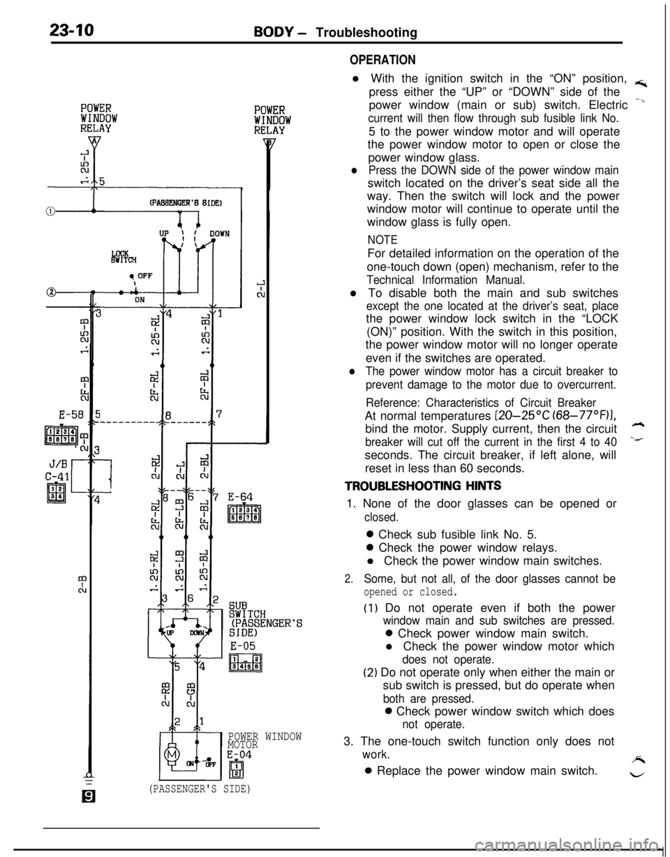
OPERATIONl With the ignition switch in the “ON” position,
rs;,press either the “UP” or “DOWN” side of the
power window (main or sub) switch. Electric
-*
current will then flow through sub fusible link No.5 to the power window motor and will operate
the power window motor to open or close the
power window glass.
lPress the DOWN side of the power window mainswitch located on the driver’s seat side all the
way. Then the switch will lock and the power
window motor will continue to operate until the
window glass is fully open.
NOTEFor detailed information on the operation of the
one-touch down (open) mechanism, refer to the
Technical Information Manual.l To disable both the main and sub switches
except the one located at the driver’s seat, placethe power window lock switch in the “LOCK
(ON)” position. With the switch in this position,
the power window motor will no longer operate
even if the switches are operated.
lThe power window motor has a circuit breaker to
prevent damage to the motor due to overcurrent.
Reference: Characteristics of Circuit BreakerAt normal temperatures
[ZO-25OC (68-77”F)I,bind the motor. Supply current, then the circuit
h
breaker will cut off the current in the first 4 to 40\&’seconds. The circuit breaker, if left alone, will
reset in less than 60 seconds.
TROUBLESHOOTING HINTS1. None of the door glasses can be opened or
closed.0 Check sub fusible link No. 5.0 Check the power window relays.
l Check the power window main switches.
2.Some, but not all, of the door glasses cannot be
opened or closed.
(I) Do not operate even if both the power
window main and sub switches are pressed.0 Check power window main switch.
l Check the power window motor which
does not operate.
(2) Do not operate only when either the main or
sub switch is pressed, but do operate when
both are pressed.0 Check power window switch which does
not operate.3. The one-touch switch function only does not
work.A0 Replace the power window main switch.
w
(PASSENGER'S SIDE)
Page 1058 of 1216
23-14BODY - Troubleshooting
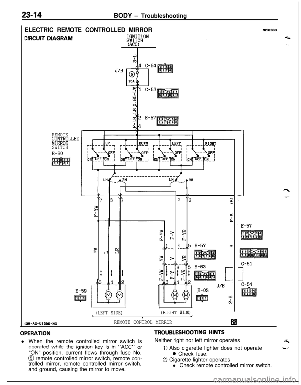
ELECTRIC REMOTE CONTROLLED MIRROR
CIRCUIT DIAGRAM
REMOTE&;;NT;LLED
SWITCH
MS-AC-UlSW-NC
L\/\I7
F
cl,,C
F
#
E-59
IpJJ%J
\/
3‘9g
4t
5
IL
;,,5 E-57m.--
!3
E-63
[z
J/BE-03
II
(LEFT SIDE)(RIGHT SIDE)LJt
REMOTE CONTROL MIRROR
1
-
i'
E-57
N23EBBD
OPERATIONl When the remote controlled mirror switch is
operated while the ignition key is in “ACC” or“ON” position, current flows through fuse No.@ remote controlled mirror switch, remote
con-trolled mirror, remote controlled mirror switch,
and ground, causing the mirror to move.
TROUBLESHOOTING HINTSNeither right nor left mirror operates
1) Also cigarette lighter does not operate0 Check fuse.
2) Cigarette lighter operates
l Check remote controlled mirror switch.
Page 1059 of 1216
c
BODY - Troubleshooting2345
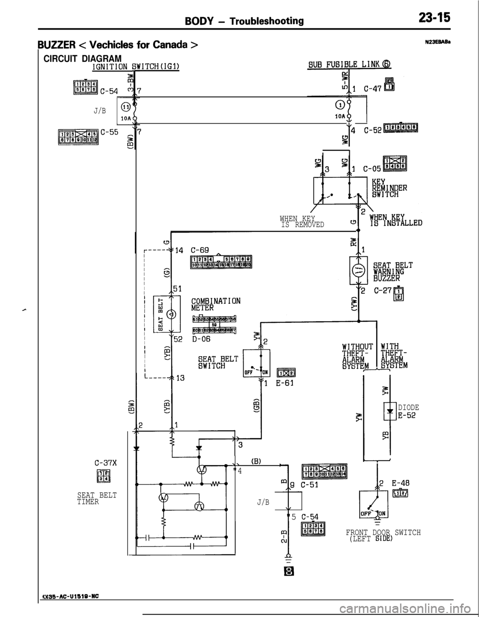
IUZZER < Vechicles for Canada >
CIRCUIT DIAGRAMIGNITION
J/B0
10A
c-37x
El34
SEAT BELT
TIMER
'ITCH(IG1)
1OA
y4 C-52
/
WHEN KEYIS REMOVED4,
II
I
I
I
I
I
IIII
I
I
II
I
I
I
I
IIIIIII
.
6
I=3?;IWELTBUZZER
\\ (B)
"4
J/B\I
"5 c-54
WITH
R!Ei&-ESTEM
DIODE
E-52
91FRONT DOOR SWITCH
cu(LEFT SIDE)
N23EBABa
KX35-AC-UlblB-NC