ignition MITSUBISHI ECLIPSE 1991 Manual Online
[x] Cancel search | Manufacturer: MITSUBISHI, Model Year: 1991, Model line: ECLIPSE, Model: MITSUBISHI ECLIPSE 1991Pages: 1216, PDF Size: 67.42 MB
Page 579 of 1216
AUTO-CRUISE CONTROL SYSTEM - Troubleshooting
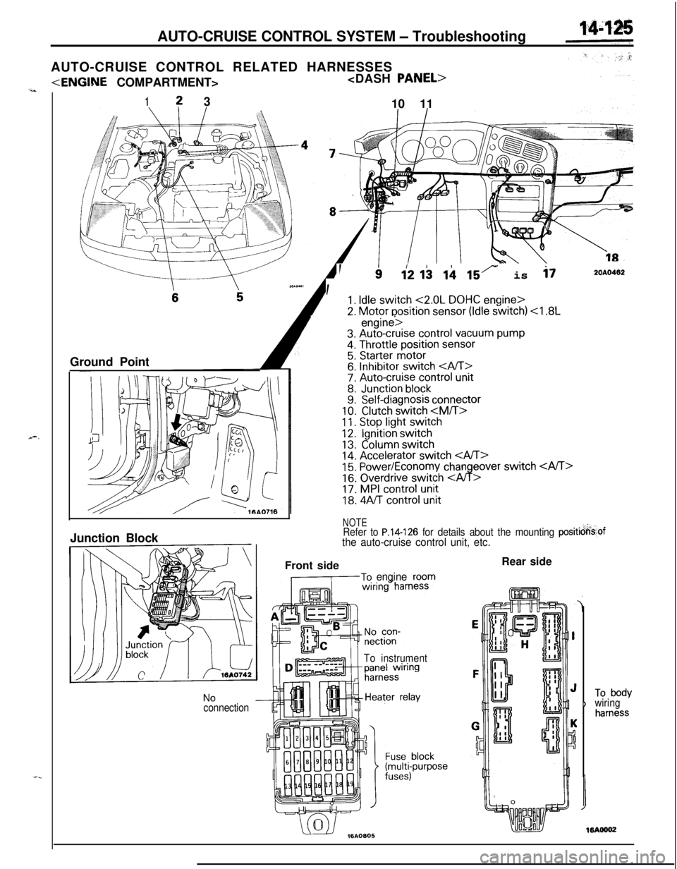
AUTO-CRUISE CONTROL RELATED HARNESSES
1? 3
10 11
Ground Point
--
, ’
112 I$ ii 15r is i72OAO402
1. Idle switch <2.0L DOHC engine>
2. Motor position sensor (Idle switch)
11. Stop light switch12.Ignition switch
13.Column switch14. Accelerator switch 15. Power/Economy changeover switch
16. Overdrive switch
18. 4Aff control unit
NOTERefer to P.14-126 for details about the mounting positicjkof
the auto-cruise control unit, etc.Junction Block
NoconnectionFront side
,-To engineroom
To instrumentRear side
)To bodywiringharness
Page 582 of 1216
14-128AUTO-CRUISE CONTROL SYSTEM - Troubleshooting
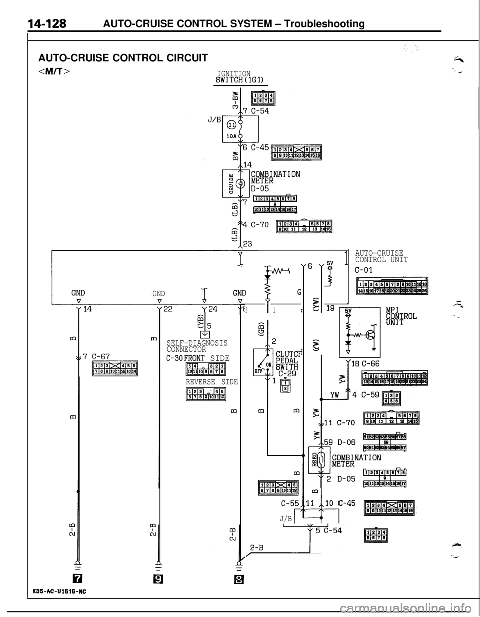
AUTO-CRUISE CONTROL CIRCUIT
GND
r GND $
1
AUTO-CRUISE
CONTROL UNIT
c-01
m
Gz5
idSELF-DIAGNOSIS
CONNECTOR
C-30FRONT SIDE
p&igq
REVERSE SIDE
pl$LzqV
v vI
311195v
izs?I
"'I
E-1 -IF4
L
II
mmm
m
pzr$iiq
c-55
J/Br
m
11 10 c-45
47
2-B ‘--ya’ pliq,
X35-AC-Ul516-NC
Page 583 of 1216
AUTO-CRUISE CONTROL SYSTEM - Trdubleshooting
IGNITIONSWITCH(lG1)
J/B
yl8 y17
C”
COLUMN SWITCH
AUTO-CRUISE
CONTROL
0.85-GW
0
20.85-GOPENEEECToR
E
SIBLE1
c-47 ~ ‘
I
J/B
3 c-55
16
AUTO-CRUISEc-01CONTROL UNIT
Page 585 of 1216
AUTO-CRUISE CONTROL SYSTEM - Troubleshooting14L’1.31”
-=cA/T>
SUB
LIN
!z
A
c
0
10A
c3
c3
h'HEN{EY IS?EMOVED
c
2Iu-zn
r
:ONI(IG1) ,INIGNITIONST)SWITCH(IG2)
-1
SIBLE
4
raII31
c-47
1
J/B
C-52
(liIals14r51sl]
IGNITISWITCI
1 J/B10A
3 c-50
7Flimsq’
z
6 c-45
14
LW$NATION
9
I, ,D-05
‘71(2~3~41516~715“‘I0 1lo~llll~l3ll4pm7
WITH
iEK;Si-
#gpT
ALARMSYSTEM I SYSTEMI,
AUTO-CRUI6E,23 CONTROL UNIT
73
i
GND
14
m10
C-67
m
0
KX35-AC-Ul516-NCn
SELF-DIAGNOSISCOt$NECTOR
c-30 :
FRONT 'SIDE
piELRq
REVERSE ,-SIDE
Page 586 of 1216

14-132AUTO-CRUISE CONTROL SYSTEM - Troubleshooting
4ci
IGNITIONSWITCHtlGl)
CR”
I
AUTO-CRUISE
CONTROL UNIT
c-01
B
1COLUMN SWITCH
AUTO-CRUISE
>CONTROL SWITCH
T C-06
I
\,4
STOPLIGHT '~------
"ITCH OP?“ONc-03ON
+I1
2
hS3 O
0
s0.65-G
SUB 1LINK
!i
L!
0
L15A
I0.85-GW-0.85-GW1
!5
OPEN
CONNECTORc-02
1IQI2E
;SIBLE
qB
1 d-47
J/B6
C-55
16
AUTO-CRUISEc-01CONTROL UNIT
Page 589 of 1216
AUTO-CRUISE CONTROL SYSTEM L service Adjustkt Procedw&
03A0258
YSET
03AO258
03AO250
SET
03A025t
JI
SERVICE ADJUSTMENT PROCEDURESNl4FUU
AUTO-CRUISE CONTROL SYSTEM INSPECTION
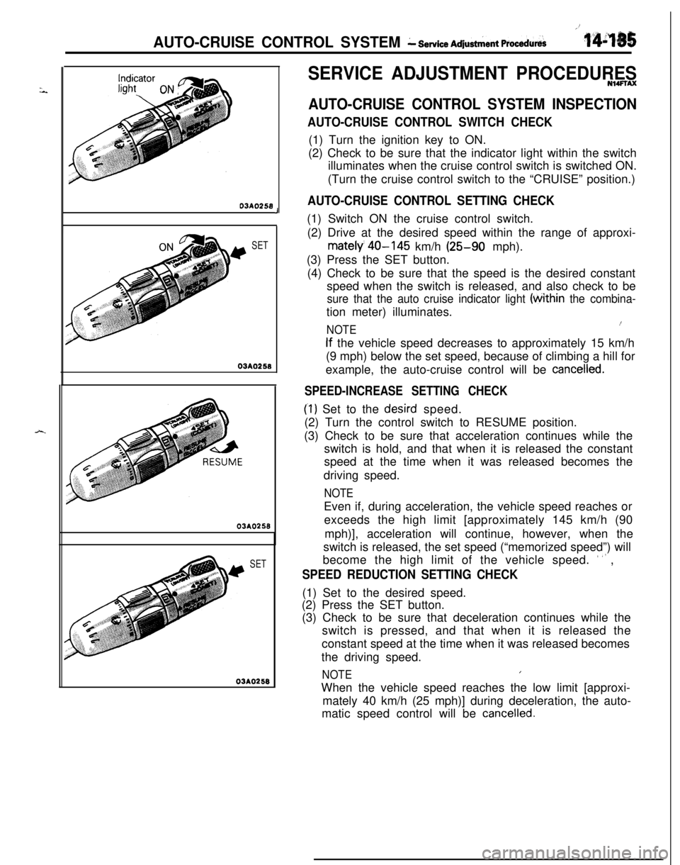
AUTO-CRUISE CONTROL SWITCH CHECK(1) Turn the ignition key to ON.
(2) Check to be sure that the indicator light within the switch
illuminates when the cruise control switch is switched ON.
(Turn the cruise control switch to the “CRUISE” position.)
AUTO-CRUISE CONTROL SETTING CHECK(1) Switch ON the cruise control switch.
(2) Drive at the desired speed within the range of approxi-
mately 40-145 km/h (25-90 mph).
(3) Press the SET button.
(4) Check to be sure that the speed is the desired constant
speed when the switch is released, and also check to be
sure that the auto cruise indicator light (tithin the combina-tion meter) illuminates.
NOTE1(
If the vehicle speed decreases to approximately 15 km/h
(9 mph) below the set speed, because of climbing a hill for
example, the auto-cruise control will be
cancelled.
SPEED-INCREASE SETTING CHECK
(‘1) Set to the desird speed.
(2) Turn the control switch to RESUME position.
(3) Check to be sure that acceleration continues while the
switch is hold, and that when it is released the constant
speed at the time when it was released becomes the
driving speed.
NOTEEven if, during acceleration, the vehicle speed reaches or
exceeds the high limit [approximately 145 km/h (90
mph)], acceleration will continue, however, when the
switch is released, the set speed (“memorized speed”) will
become the high limit of the vehicle speed.
’ ” ,
SPEED REDUCTION SETTING CHECK(1) Set to the desired speed.
(2) Press the SET button.
(3) Check to be sure that deceleration continues while the
switch is pressed, and that when it is released the
constant speed at the time when it was released becomes
the driving speed.
NOTEIWhen the vehicle speed reaches the low limit [approxi-
mately 40 km/h (25 mph)] during deceleration, the auto-
matic speed control will be
cancelled.
Page 590 of 1216
14-136AUTO-CRUISE CONTROL SYSTEM- Service Adjustment Procedures03AQ250
rdjusting
03A0281
AUTO-CRUISE CONTROL CANCELLATION CHECK(1) Set the auto-cruise control.
”(2) Check to be sure that there is a return to ordinary driving,
and that the illumination of the auto-cruise indicator stops,
‘cwhen either of the operations below is performed.
@ The brake pedal is depressed.
@ The clutch pedal is depressed.
@ The shift lever is moved to the “N” or “P” range.
aIT>
@ The auto-cruise control main switch is switched OFF.
@ The ignition switch is turned to OFF.
CHECK OF RETURN TO THE SET SPEED BEFORE
CANCELLATION(1) Set the auto-cruise control.
(2) Check to be sure that the auto-cruise control is
cancelledwhen either of the operations below is performed.
@ The brake pedal is depressed.
@ The clutch pedal is depressed.
@I The shift lever is moved to the “N” range. (3) Turn the control switch to RESUME position and release
(RESUME switch
ONdOFF) while driving at a vehicle
speed of approximately 40 km/h (25 mph) or higher.
(4) After switching RESUME switch to OFF, check to be sure
that there is a return to the auto-cruise control speed before
it will be
cancelled and the vehicle will travel at the constant
speed.
A
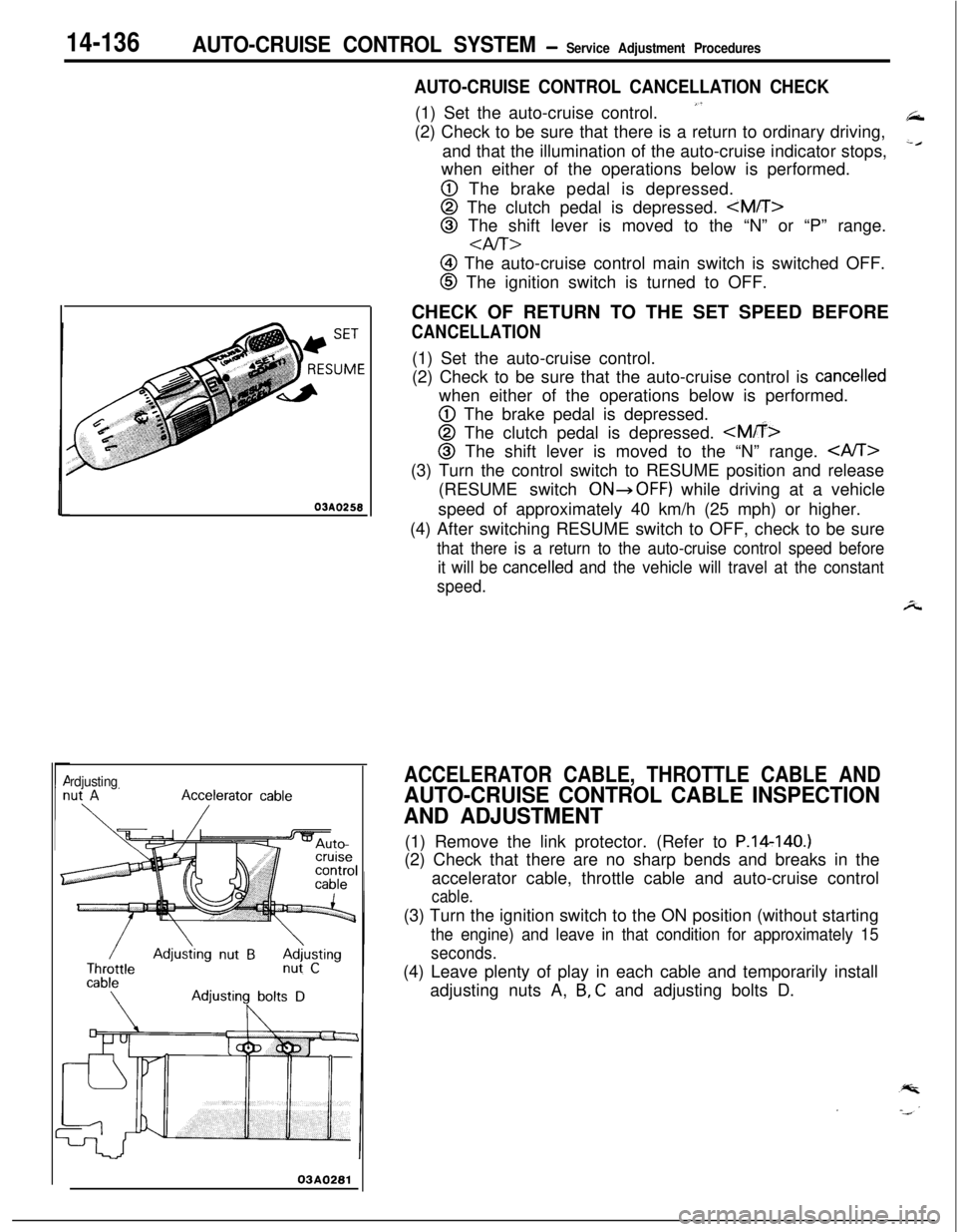
ACCELERATOR CABLE, THROTTLE CABLE AND
AUTO-CRUISE CONTROL CABLE INSPECTION
AND ADJUSTMENT(1) Remove the link protector. (Refer to P.14140.)
(2) Check that there are no sharp bends and breaks in the
accelerator cable, throttle cable and auto-cruise control
cable.(3) Turn the ignition switch to the ON position (without starting
the engine) and leave in that condition for approximately 15
seconds.(4) Leave plenty of play in each cable and temporarily install
adjusting nuts A,
B, C and adjusting bolts D.
Page 661 of 1216
STEERING - Service -Adjustment Procedures < Power Steering >IgJf~
4.Disconnect the high-tension cable, and then while operating
the starting motor intermittently, turn the steering wheel all;
the way to the left and right several times to drain all of the
fluid.
Caution, 35
Be careful not to position thq high-tension able ye&r the
carburetor or the delivery pipe.5. Connect the return hoses securely, and then
secur& it ,with
the clip.6. Fill the oil reservoir with the specified fluid up
td the Ibwerposition of the filter, and then bleed the air.
.’
Specified fluid:MOPAR ATF PLUS (Automatic Transmis-sion Fluid Type 7176)/Automatic trans-
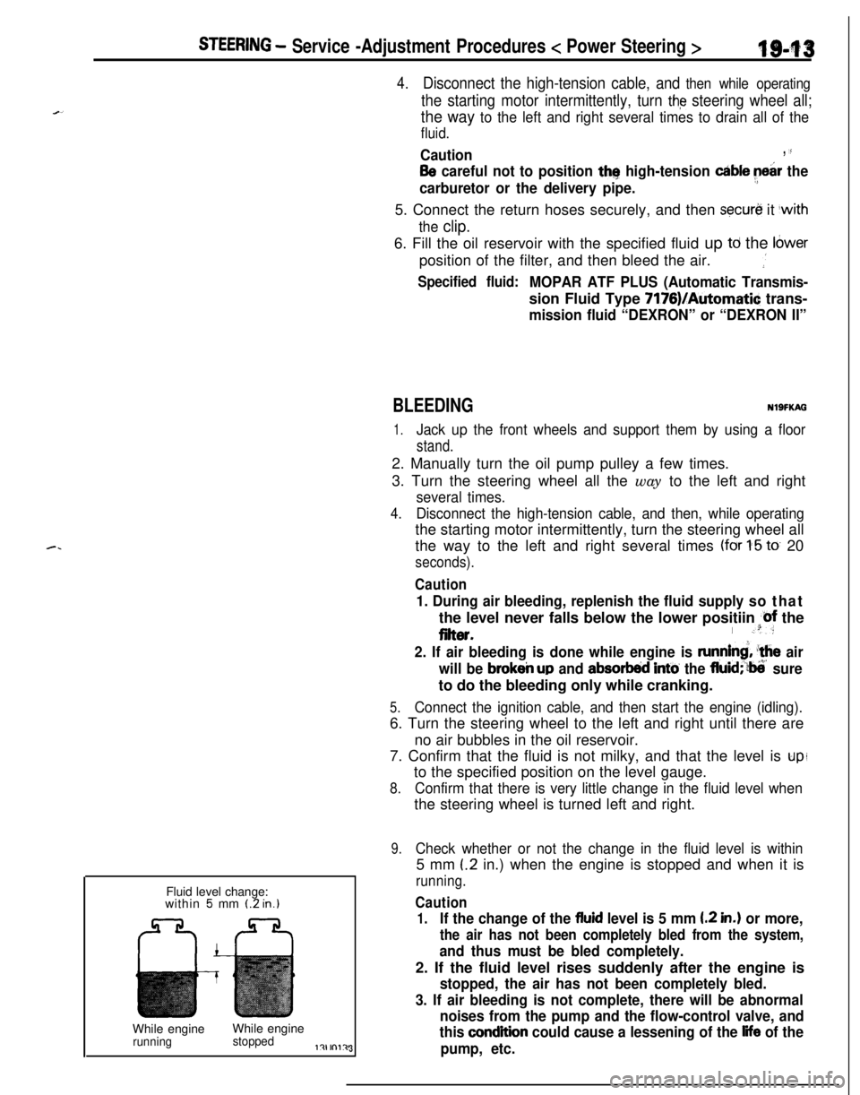
mission fluid “DEXRON” or “DEXRON II”Fluid level change:
within
5 mm (2 in.)While engineWhile engine
runningstoppedl?lrnl?J3
BLEEDINGNlSFKAG
1.Jack up the front wheels and support them by using a floor
stand.2. Manually turn the oil pump pulley a few times.
3. Turn the steering wheel all the way to the left and right
several times.
4.Disconnect the high-tension cable, and then, while operatingthe starting motor intermittently, turn the steering wheel all
the way to the left and right several times
(for 1-5 to 20
seconds).
Caution
1. During air bleeding, replenish the fluid supply so thatthe level never falls below the lower positiin
@f the
eiter.I .“:
2. If air bleeding is done while engine is runnind, ‘the air
will be
brokeir up and absorbed intti the fluid;‘?ti’ sureto do the bleeding only while cranking.
5.Connect the ignition cable, and then start the engine (idling).6. Turn the steering wheel to the left and right until there are
no air bubbles in the oil reservoir.
7. Confirm that the fluid is not milky, and that the level is
upito the specified position on the level gauge.
8.Confirm that there is very little change in the fluid level whenthe steering wheel is turned left and right.
9.Check whether or not the change in the fluid level is within5 mm
(.2 in.) when the engine is stopped and when it is
running.
Caution
1.If the change of the fluid level is 5 mm I.2 in.) or more,
the air has not been completely bled from the system,
and thus must be bled completely.2. If the fluid level rises suddenly after the engine is
stopped, the air has not been completely bled.
3. If air bleeding is not complete, there will be abnormal
noises from the pump and the flow-control valve, and
this
condition could cause a lessening of the life of the
pump, etc.
Page 872 of 1216
21-178AUTOMATIC TRANSAXLE - Troubleshooting
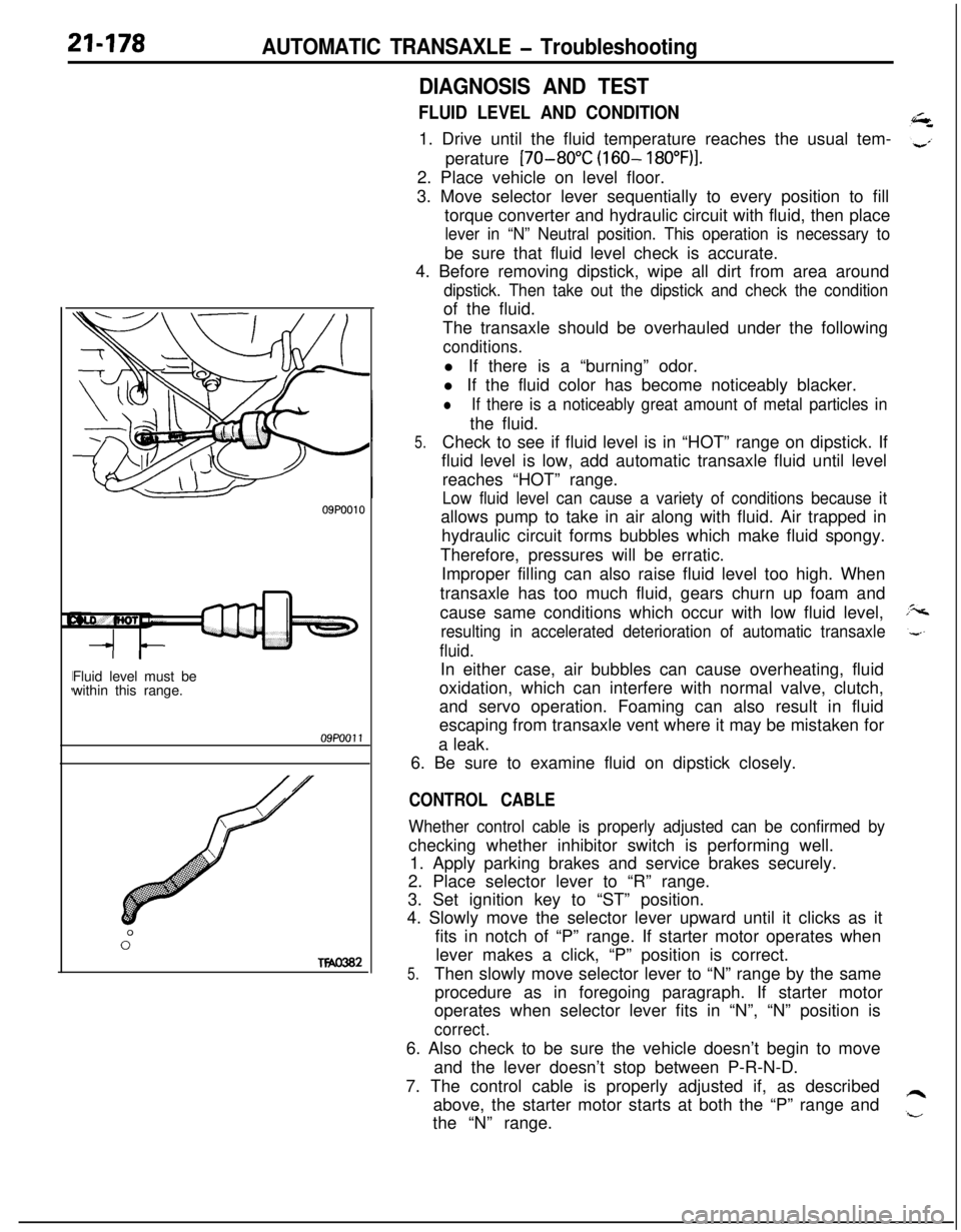
09P0010Fluid level must be
within this range.09PoOll
0”
Two302
DIAGNOSIS AND TEST
FLUID LEVEL AND CONDITION1. Drive until the fluid temperature reaches the usual tem-
perature
[70-80°C (160- 18O”F)I.2. Place vehicle on level floor.
3. Move selector lever sequentially to every position to fill
torque converter and hydraulic circuit with fluid, then place
lever in “N” Neutral position. This operation is necessary tobe sure that fluid level check is accurate.
4. Before removing dipstick, wipe all dirt from area around
dipstick. Then take out the dipstick and check the conditionof the fluid.
The transaxle should be overhauled under the following
conditions.l If there is a “burning” odor.
l If the fluid color has become noticeably blacker.
lIf there is a noticeably great amount of metal particles inthe fluid.
5.Check to see if fluid level is in “HOT” range on dipstick. If
fluid level is low, add automatic transaxle fluid until level
reaches “HOT” range.
Low fluid level can cause a variety of conditions because itallows pump to take in air along with fluid. Air trapped in
hydraulic circuit forms bubbles which make fluid spongy.
Therefore, pressures will be erratic.
Improper filling can also raise fluid level too high. When
transaxle has too much fluid, gears churn up foam and
cause same conditions which occur with low fluid level,
resulting in accelerated deterioration of automatic transaxle
fluid.In either case, air bubbles can cause overheating, fluid
oxidation, which can interfere with normal valve, clutch,
and servo operation. Foaming can also result in fluid
escaping from transaxle vent where it may be mistaken for
a leak.
6. Be sure to examine fluid on dipstick closely.
CONTROL CABLE
Whether control cable is properly adjusted can be confirmed bychecking whether inhibitor switch is performing well.
1. Apply parking brakes and service brakes securely.
2. Place selector lever to “R” range.
3. Set ignition key to “ST” position.
4. Slowly move the selector lever upward until it clicks as it
fits in notch of “P” range. If starter motor operates when
lever makes a click, “P” position is correct.
5.Then slowly move selector lever to “N” range by the same
procedure as in foregoing paragraph. If starter motor
operates when selector lever fits in “N”, “N” position is
correct.6. Also check to be sure the vehicle doesn’t begin to move
and the lever doesn’t stop between P-R-N-D.
7. The control cable is properly adjusted if, as described
above, the starter motor starts at both the “P” range and
the “N” range.
Page 873 of 1216
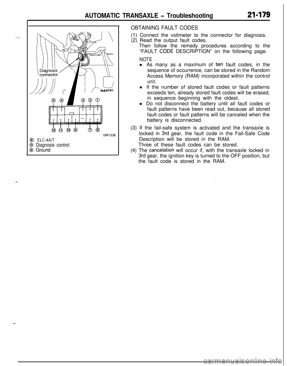
AUTOMATIC TRANSAXLE - Troubleshooting21-179
@: ELC-4PJT
@I: Diagnosis control
0: Ground
16R1336
OBTAINING FAULT CODES(1) Connect the voltmeter to the connector for diagnosis.
(2) Read the output fault codes.
Then follow the remedy procedures according to the
“FAULT
CODE DESCRIPTION” on the following page.
NOTEl As many as a maximum of
terr fault codes, in the
sequence of occurrence, can be stored in the Random
Access Memory (RAM) incorporated within the control
unit.l If the number of stored fault codes or fault patterns
exceeds ten, already stored fault codes will be erased,
in sequence beginning with the oldest.
l Do not disconnect the battery until all fault codes or
fault patterns have been read out, because all stored
fault codes or fault patterns will be canceled when the
battery is disconnected.
(3) If the fail-safe system is activated and the transaxle is
locked in
3rd gear, the fault code in the Fail-Safe Code
Description will be stored in the RAM.
Three of these fault codes can be stored.
(4) The
cancelation will occur if, with the transaxle locked in
3rd gear, the ignition key is turned to the OFF position, but
the fault code is stored in the RAM.