belt MITSUBISHI ECLIPSE 1991 Owner's Manual
[x] Cancel search | Manufacturer: MITSUBISHI, Model Year: 1991, Model line: ECLIPSE, Model: MITSUBISHI ECLIPSE 1991Pages: 1216, PDF Size: 67.42 MB
Page 272 of 1216
7-24COOLING - Water Pump <2.0L DOHC Engine>
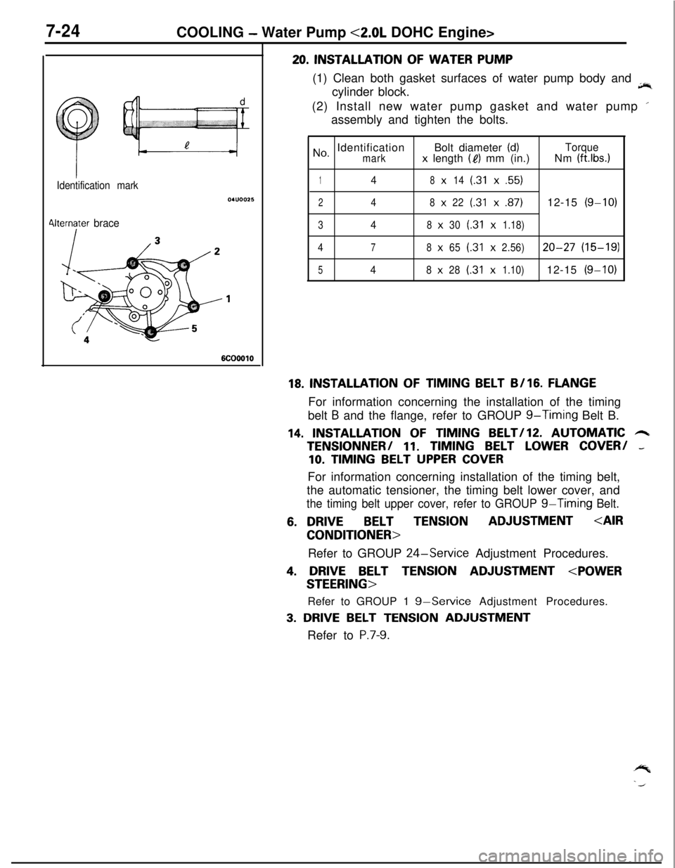
Identification mark
4lternater brace
6COOOlO
20. INSTALLATION OF WATER PUMP
(1) Clean both gasket surfaces of water pump body and
jir,cylinder block.
(2) Install new water pump gasket and water pump ’
assembly and tighten the bolts.
No, IdentificationBolt diameter (d)Torquemarkx length (I?) mm (in.)Nm (ft.lbs.1
148x14(.31x.55)
248x22(.31x.87)12-15(g-10)
348x30(.31x1.18)
4
78x65(.31x2.56)20-27(15-191
548x28(.31x1.10)12-15(g-10)
18. INSTALLATION OF TIMING BELT B/16. FLANGEFor information concerning the installation of the timing
belt
B and the flange, refer to GROUP g-Timing Belt B.
14. INSTALLATION OF TIMING BELT/lZ. AUTOMATIC 6TENSlONNER/
11. TIMING BELT LOWER COVER/ -
10. TIMING BELT UPPER COVERFor information concerning installation of the timing belt,
the automatic tensioner, the timing belt lower cover, and
the timing belt upper cover, refer to GROUP g-Timing Belt.
6. DRIVEBELT TENSIONADJUSTMENT
Refer to GROUP
24-Service Adjustment Procedures.
4. DRIVE BELT TENSION ADJUSTMENT
Refer to GROUP 1
g-Service Adjustment Procedures.
3. DRIVE BELT TENSION ADJUSTMENT
Refer to
P.7-9.
Page 285 of 1216
9-1
ENGINE
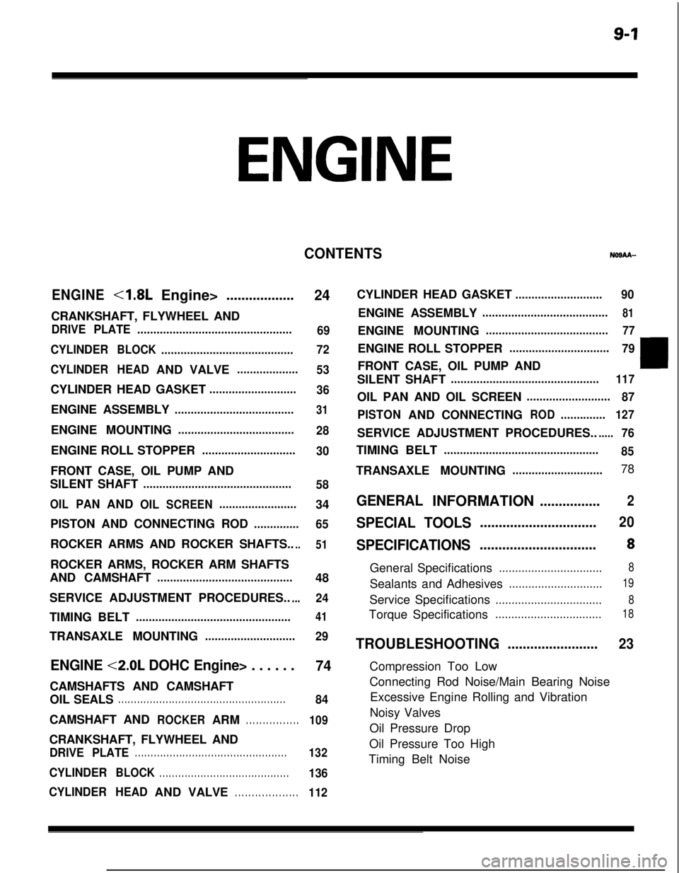
CONTENTSNOSAA-
ENGINE<1.8L
Engine>..................
24CRANKSHAFT, FLYWHEEL AND
DRIVE PLATE................................................
69
CYLINDER
BLOCK.........................................72
CYLINDERHEADANDVALVE
...................
53CYLINDER HEAD GASKET
...........................
36ENGINE ASSEMBLY
.....................................31ENGINE MOUNTING
....................................
28ENGINE ROLL STOPPER
.............................
30FRONT CASE, OIL PUMP AND
SILENT SHAFT
..............................................
58
OILPANANDOILSCREEN........................34
PISTON AND CONNECTING ROD
..............
65ROCKER ARMS AND ROCKER SHAFTS..
..51ROCKER ARMS, ROCKER ARM SHAFTS
AND CAMSHAFT
..........................................48
SERVICE ADJUSTMENT PROCEDURES..
...24TIMING BELT
................................................41TRANSAXLE MOUNTING
............................
29
ENGINE <2.0L DOHC Engine> . . . . . .
74CAMSHAFTS AND CAMSHAFT
OIL SEALS
. . . . . . . . . . . . . . . . . . . . . . . . . . . . . . . . . . . . . . . . . . . . . . . . . . . . .84CAMSHAFTAND
ROCKERARM. . . . . . . . . . . . . . . .109CRANKSHAFT, FLYWHEEL AND
DRIVE PLATE. . . . . . . . . . . . . . . . . . . . . . . . . . . . . . . . . . . . . . . . . . . . . . . .132
CYLINDERBLOCK. . . . . . . . . . . . . . . . . . . . . . . . . . . . . . . . . . . . . . . . .136
CYLINDERHEADANDVALVE
. . . . . . . . . . . . . . . . . . .112CYLINDER HEAD GASKET
...........................90ENGINE ASSEMBLY
.......................................81ENGINE MOUNTING
......................................77ENGINE ROLL STOPPER
...............................
79FRONT CASE, OIL PUMP AND
SILENT SHAFT
..............................................117OIL PAN AND OIL SCREEN
..........................
87
PISTONANDCONNECTING
ROD..............127SERVICE ADJUSTMENT PROCEDURES..
.....76TIMING BELT
................................................
85TRANSAXLE MOUNTING
............................78
GENERALINFORMATION................2
SPECIAL TOOLS...............................20
SPECIFICATIONS...............................8General Specifications
................................8Sealants and Adhesives
.............................19Service Specifications
.................................8Torque Specifications
.................................18
TROUBLESHOOTING........................23Compression Too Low
Connecting Rod Noise/Main Bearing Noise
Excessive Engine Rolling and Vibration
Noisy Valves
Oil Pressure Drop
Oil Pressure Too High
Timing Belt Noise
Page 292 of 1216
9-8ENGINE - Specifications
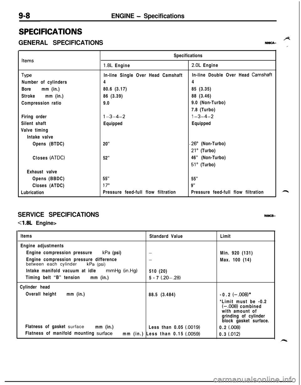
SPECIFICATIONS
GENERAL SPECIFICATIONSBNDBCA-
Items
TypeNumber of cylinders
Boremm (in.)
Strokemm (in.)
Compression ratio
Firing order
Silent shaft
Valve timing
Intake valve
Opens (BTDC)
Closes
(ATDC)Exhaust valve
Opens (BBDC)
Closes (ATDC)
LubricationSpecifications
1.8L Engine2.0L Engine
In-line Single Over Head CamshaftIn-line Double Over Head
Camshafi44
80.6 (3.17)85 (3.35)
86 (3.39)88 (3.46)
9.09.0 (Non-Turbo)
7.8 (Turbo)
l-3-4-21-3-4-2EquippedEquipped
20”
.26” (Non-Turbo)
21’ (Turbo)
52”46” (Non-Turbo)
51’ (Turbo)
55”
55”
17”9”Pressure feed-full flow filtrationPressure feed-full flow filtration
SERVICE SPECIFICATIONSNOSCB-
-4.8L Engine>
Items
Standard Value
Engine adjustments
Engine compression pressurekPa (psi)
-Engine compression pressure difference
-between each cylinder
kPa (psi)
Intake manifold vacuum at idle
mmHg (in.Hg)510 (20)
Timing belt “B” tension
mm (in.)
5-7
(.20-.28)Cylinder head
Overall height
mm (in.)
88.5 (3.484)
Flatness of gasket surface
mm (in.)
Less than 0.05
(0019)Flatness of manifold mounting
surfacemm (in.) Less than 0.15 (.0059)Limit
Min. 920 (131)
Max. 100 (14)
-0.2
(-.008)**Limit must be -0.2
(-.008) combined
with amount of
grinding of cylinder
block gasket surface.
0.2
(008)0.3
(.012)
Page 296 of 1216
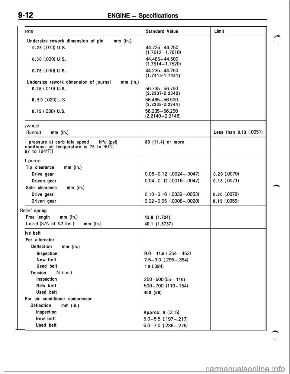
9-12ENGINE - Specifications3msStandard ValueLimit
Undersize rework dimension of pinmm (in.)
0.25
f.010) U.S.44.735-44.750
(1.7612-1.7618)0.50
(.020) U.S.44.485-44.500
(1.7514-1.7520)0.75
(030) U.S.44.235-44.250(1.7415-1.7421)
Undersize rework dimension of journalmm (in.)
0.25
(.OlO) U.S.56.735-56.750(2.2337-2.2342)
0.50
(020) U.S.56.485-56.500(2.2238-2.2244)
0.75
(.030) U.S.56.235-56.250
(2.2140-2.2146)
wheelRunoutmm (in.)Less than 0.13
(0051)I pressure at curb idle speedkPa (psi)80 (11.4) or more
onditions: oil temperature is 75 to
90°C67 to 194”F)l
1 w-wTip clearancemm (in.)
Drive gear
0.06-0.12 (.0024-.0047)0.20 i.0079)Driven gear
0.04-O. 12 (.0016-.0047)0.18 (.0071)Side clearancemm (in.)
Drive gear
0.10-0.16 (.0039-.0063)0.20 (.0079)Driven gear
0.02-0.05 (.0008-.0020)0.15 (.0059)
rlief spring
Free lengthmm (in.)
43.8 (1.724)
Load
[37N at 8.2 Ibs.]mm (in.)
40.1 (1.5787)
ive belt
For alternator
Deflection
mm (in.)
Inspection
9.0- 11.5 (.354-,453)New belt
7.5-9.0 (.295-.354)Used belt
10
i.394)TensionN (Ibs.)
Inspection
250-500 (55- 110)
New belt
500-700 (110-154)Used belt
400 (88)
For air conditioner compressor
Deflectionmm (in.)
Inspection
Approx. 8
(315)New belt
5.0-5.5 (.197-.217)Used belt
6.0-7.0 (.236-.276)
Page 297 of 1216
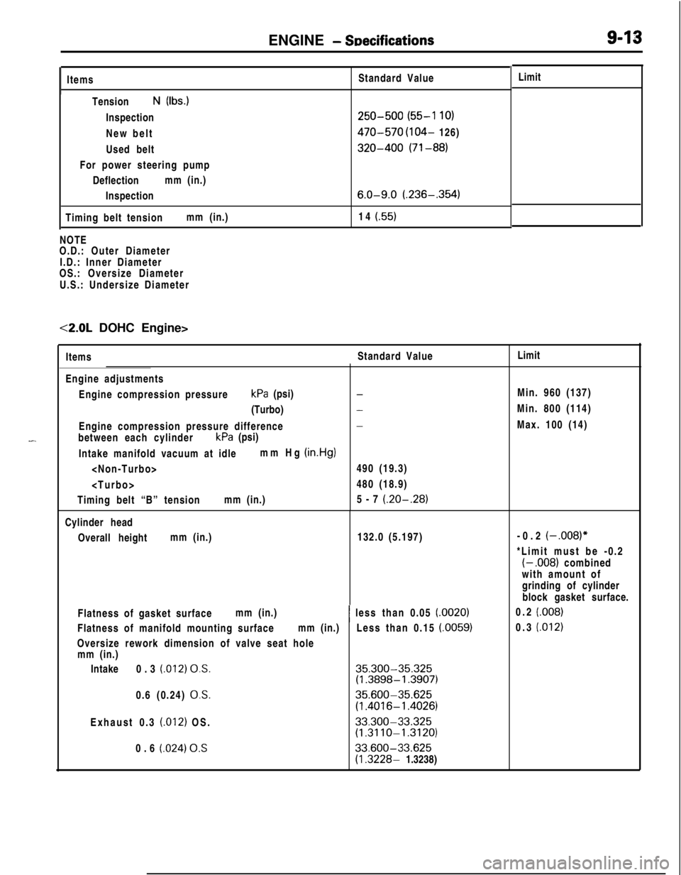
ENGINE - SDecificationsItems
TensionN (Ibs.)
Inspection
New belt
Used belt
For power steering pump
Deflectionmm (in.)
Inspection
Timing belt tensionmm (in.)Standard Value
250-500 (55-l 10)
470-570 (104- 126)
320-400 (71-88)
6.0-9.0 (.236-.354)14
(.55)NOTE
O.D.: Outer Diameter
I.D.: Inner Diameter
OS.: Oversize Diameter
U.S.: Undersize Diameter<2.0L DOHC Engine>
-ItemsStandard ValueLimit
Engine adjustments
Engine compression pressurekPa (psi)
(Turbo)
Engine compression pressure difference
between each cylinderkPa (psi)
Intake manifold vacuum at idlemm Hg
(in.Hg)
Timing belt “B” tensionmm (in.)
-
-
-490 (19.3)
480 (18.9)
5-7
(.20-.28)Cylinder head
Overall heightmm (in.)132.0 (5.197)
Flatness of gasket surfacemm (in.)
Flatness of manifold mounting surfacemm (in.)
Oversize rework dimension of valve seat hole
mm (in.)
Intake0.3
(.012) 0,s.0.6 (0.24)
0,s.Exhaust 0.3
(.012) OS.
0.6
(.024) 0.S~ less than 0.05
(.0020)Less than 0.15
(.0059)
35.300-35.325(1.3898-1.3907)
35.600-35.625
(1.4016-l .4026)
33.300-33.325(1.3110-1.3120)
33.600-33.625
(1.3228- 1.3238)Limit
Min. 960 (137)
Min. 800 (114)
Max. 100 (14)
-0.2
(-,008)”*Limit must be -0.2
(- .008) combined
with amount of
grinding of cylinder
block gasket surface.
0.2
(.008)0.3
(.012)
Page 301 of 1216
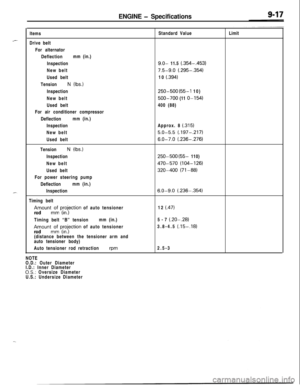
ENGINE - Specifications
..--Items
Drive belt
For alternator
Deflectionmm (in.)
Inspection
New belt
Used belt
Tension
N (Ibs.)
Inspection
New belt
Used belt
For air conditioner compressor
Deflectionmm (in.)
Inspection
New belt
Used belt
Tension
N (Ibs.)
Inspection
New belt
Used belt
For power steering pump
Deflectionmm (in.)
Inspection
Timing belt
Amount;; I;;;j;ction of auto tensioner
rodTiming belt “B” tensionmm (in.)
Amount;: I;;;jytion of auto tensioner
rod(distance between the tensioner arm and
auto tensioner body)
Auto tensioner rod retraction
wmNOTE
O.D.: Outer Diameter
I.D.: Inner Diameter
0,s.: Oversize Diameter
U.S.: Undersize DiameterStandard Value
9.0- 11.5 (.354-.453)
7.5-9.0 (.295-.354)10
i.394)
250-500 (55-l 10)
500-700 (11 o-1 54)400 (88)
Approx. 8
(.315)
5.0-5.5 (.197-.217)
6.0-7.0 (.236-,276)
250-500 (55- 110)
470-570 (104-126)
320-400 (71-88)
6.0-9.0 (.236-,354)12
(.47)5-7
(.20-.28)3.8-4.5
(.15-,1812.5-3Limit
Page 302 of 1216
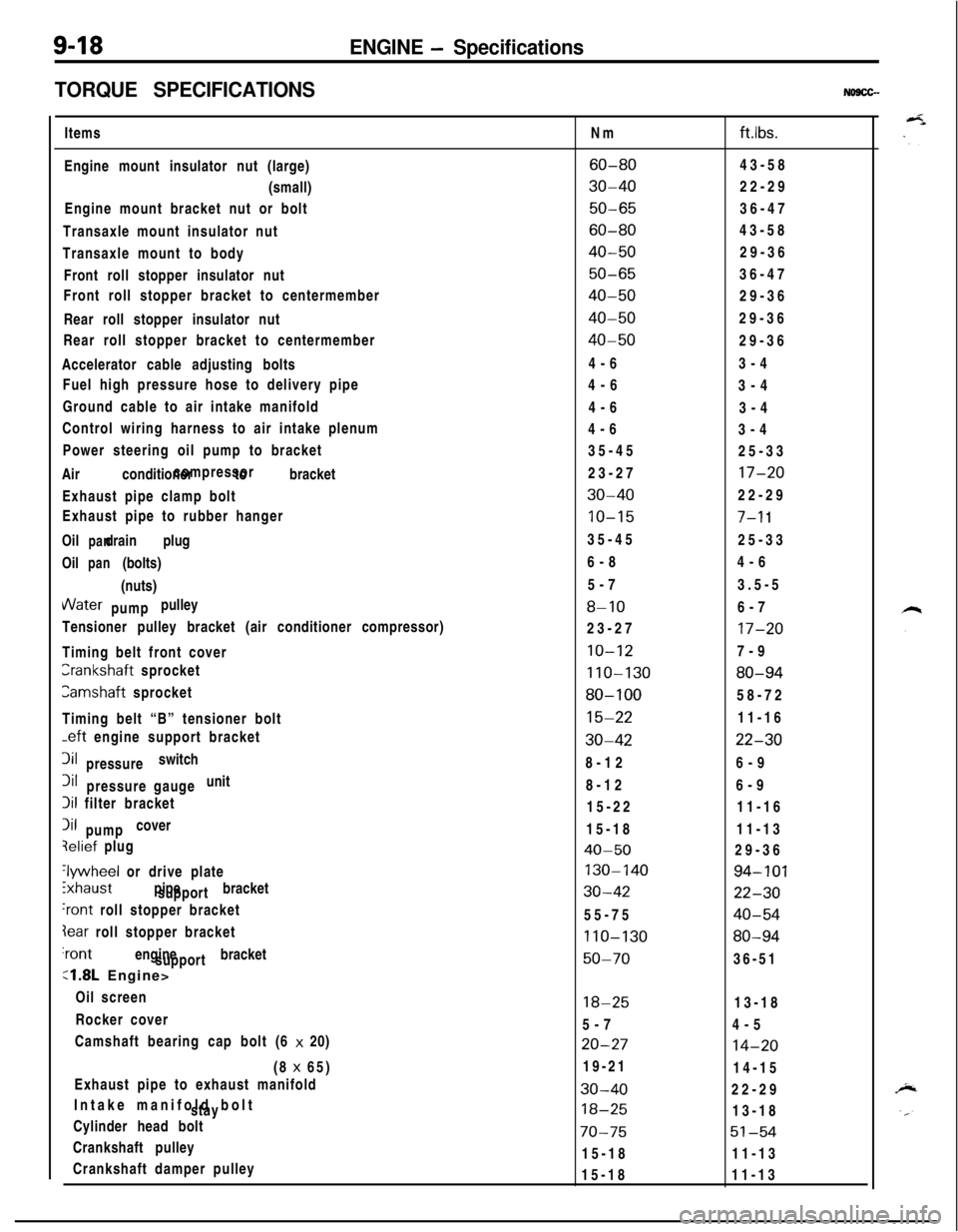
9-18ENGINE - Specifications
TORQUE SPECIFICATIONS
NO9CG-Items
Engine mount insulator nut (large)
(small)
Engine mount bracket nut or bolt
Transaxle mount insulator nut
Transaxle mount to body
Front roll stopper insulator nut
Front roll stopper bracket to centermember
Rear roll stopper insulator nut
Rear roll stopper bracket to centermember
Accelerator cable adjusting bolts
Fuel high pressure hose to delivery pipe
Ground cable to air intake manifold
Control wiring harness to air intake plenum
Power steering oil pump to bracket
Air conditioner to bracketcompressor
Exhaust pipe clamp bolt
Exhaust pipe to rubber hanger
Oil drain plug
panOil (bolts)
pan(nuts)VVater pulley
pump
Tensioner pulley bracket (air conditioner compressor)
Timing belt front coverCrankshaft sprocket
Camshaft sprocket
Timing belt “B” tensioner bolt
-eft engine support bracket3il switch
pressure3il unit
pressure gauge
Iii filter bracket
Iii cover
pumpqelief plug
‘lywheel or drive plate
ixhaust pipe bracket
support
‘rant roll stopper bracket
Iear roll stopper bracket‘rant engine bracket
support
:1.8L Engine>
Oil screen
Rocker cover
Camshaft bearing cap bolt (6 x 20)
(8 x 65)
Exhaust pipe to exhaust manifold
Intake manifold bolt
stay
Cylinder head bolt
Crankshaft pulley
Crankshaft damper pulleyNm
ftlbs.
60-8043-58
30-4022-29
50-6536-47
60-8043-58
40-5029-36
50-6536-47
40-5029-36
40-5029-36
40-5029-36
4-63-4
4-6
3-4
4-6
3-4
4-6
3-4
35-45
25-33
23-27
17-20
30-4022-29
10-157-l 135-45
25-33
6-84-6
5-73.5-5
8-106-7
23-27
17-20
10-127-9
110-13080-94
80-10058-72
15-2211-16
30-4222-308-126-9
8-126-9
15-2211-16
15-1811-13
40-5029-36
130-14094-101
30-4222-3055-75
40-54
110-13080-94
50-7036-51
18-2513-18
5-74-5
20-2714-2019-21
14-15
30-4022-29
18-2513-18
70-7551-5415-1811-13
15-1811-13
Page 303 of 1216
-
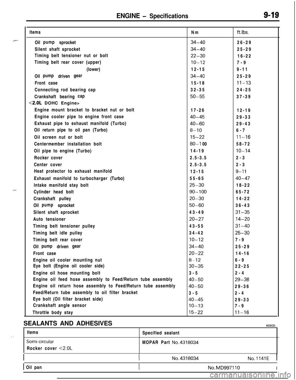
ENGINE - Specifications9-19Items
Oil sprocketpump
Silent shaft sprocket
Timing belt tensioner nut or bolt
Timing belt rear cover (upper)
(lower)
Oil drivenpump gear
Front case
Connecting rod bearing cap
Crankshaft bearingcap
<2.0L DOHC Engine>
Engine mount bracket to bracket nut or bolt
Engine cooler pipe to engine front case
Exhaust pipe to exhaust manifold (Turbo)
Oil return pipe to oil pan (Turbo)
Oil screen nut or bolt
Centermember installation bolt
Oil pipe to engine (Turbo)
Rocker cover
Center cover
Heat protector to exhaust manifold
Exhaust manifold to turbocharger(Turbo)
Intake manifold stay bolt
Cylinder head bolt
Crankshaft pulley
Oil sprocketpump
Silent shaft sprocket
Auto tensioner
Timing belt tensioner pulley
Timing belt idle pulley
Timing belt rear cover
Oil drivenpump gear
Front case
Engine oil cooler mounting nut
Eye bolt (Engine oil cooler side)
Engine oil hose mounting bolt
Engine oil feed hose assembly to Feed/Return tube assembly
Engine oil return hose assembly to Feed/Return tube assembly
Feed/Return tube assembly to oil filter bracket
Eye bolt (Oil filter bracket side)
Crankshaft angle sensor
Throttle body stayNm
ft.lbs.
34-4026-29
34-4025-29
22-3016-22
IO-127-9
12-159-11
34-4025-29
15-18
11-1332-3524-25
50-5537-39
17-26
12-19
40-4529-33
40-6029-43
8-106-7
15-2211-16
80-l 0058-72
14-19
10-142.5-3.52-3
2.5-3.52-3
12-15
9-l 155-65
40-47
25-3018-22
90-10065-72
20-3014-22
50-6036-43
43-49
31-35
20-2714-2043-55
31-4034-42
25-30
10-127-9
34-4025-29
20-2214-16
8-126-9
30-3522-25
3-52-4
40-5029-36
40-5029-36
3-52-4
40-4529-33
IO-137-9
15-2211-16SEALANTS AND ADHESIVES
NOSCE-.Items
Specified sealant
“. _
SemiWrcularMOPAR Part No.4318034Rocker cover
<2.0L
1(No.4318034No.1141~1
1 Oil pan1No.MD997110I
Page 307 of 1216
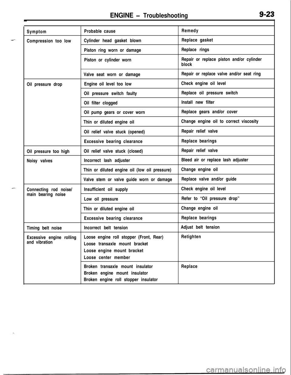
ENGINE - Troubleshooting9-23
--Symptom
Compression too lowProbable cause
Cylinder head gasket blown
Piston ring worn or damage
Piston or cylinder wornRemedy
Replace gasket
Replace rings
Repair or replace piston and/or cylinder
block
Valve seat worn or damageRepair or replace valve and/or seat ring
Oil pressure dropEngine oil level too lowCheck engine oil level
Oil pressure switch faultyReplace oil pressure switch
Oil filter cloggedInstall new filter
Oil pump gears or cover wornReplace gears and/or cover
Thin or diluted engine oilChange engine oil to correct viscosity
Oil relief valve stuck (opened)Repair relief valve
Excessive bearing clearanceReplace bearings
Oil pressure too highOil relief valve stuck (closed)Repair relief valve
Noisy valvesIncorrect lash adjusterBleed air or replace lash adjuster
Thin or diluted engine oil (low oil pressure)Change engine oil
Valve stem or valve guide worn or damageReplace valve and/or guide
Connecting rod noise/Insufficient oil supplyCheck engine oil level
main bearing noise
Low oil pressureRefer to “Oil pressure drop”
Thin or diluted engine oilChange engine oil
Excessive bearing clearanceReplace bearings
Timing belt noiseIncorrect belt tensionAdjust belt tension
Excessive engine rollingLoose engine roll stopper (Front, Rear)Retighten
and vibration
Loose transaxle mount bracket
Loose engine mount bracket
Loose center member
Broken transaxle mount insulatorReplace
Broken engine mount insulator
Broken engine roll stopper insulator
Page 310 of 1216
9-26ENGINE <1.8L Engine> -Service Adjustment Procedures
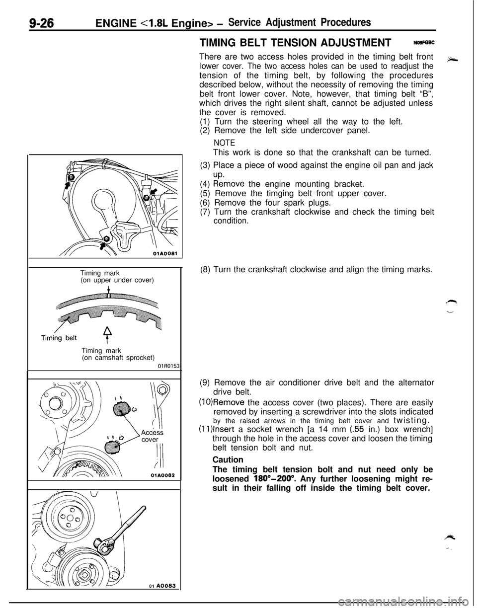
TIMING BELT TENSION ADJUSTMENTNOSFGBCThere are two access holes provided in the timing belt front
lower cover. The two access holes can be used to readjust thetension of the timing belt, by following the procedures
described below, without the necessity of removing the timing
belt front lower cover. Note, however, that timing belt “B”,
which drives the right silent shaft, cannot be adjusted unless
the cover is removed.
(1) Turn the steering wheel all the way to the left.
(2) Remove the left side undercover panel.
NOTEThis work is done so that the crankshaft can be turned.
(3) Place a piece of wood against the engine oil pan and jack
(4)
:tmove the engine mounting bracket.
(5) Remove the timging belt front upper cover.
(6) Remove the four spark plugs.
(7) Turn the crankshaft clockwise and check the timing belt
condition.
OlAOOBlTiming mark
(on upper under cover)
Timing mark
(on camshaft sprocket)
OlR0153cover
‘I!i
OlA0082
01 A0083(8) Turn the crankshaft clockwise and align the timing marks.
(9) Remove the air conditioner drive belt and the alternator
drive belt.
(10)Remove the access cover (two places). There are easily
removed by inserting a screwdriver into the slots indicated
by the raised arrows in the timing belt cover and twisting.
(1l)lnser-t a socket wrench [a 14 mm (.55 in.) box wrench]
through the hole in the access cover and loosen the timing
belt tension bolt and nut.
Caution
The timing belt tension bolt and nut need only be
loosened
180”-200”. Any further loosening might re-
sult in their falling off inside the timing belt cover.