weight MITSUBISHI ECLIPSE 1991 Service Manual
[x] Cancel search | Manufacturer: MITSUBISHI, Model Year: 1991, Model line: ECLIPSE, Model: MITSUBISHI ECLIPSE 1991Pages: 1216, PDF Size: 67.42 MB
Page 8 of 1216
8INTRODUCTION AND MASTER TROUBLESHOOTING - Vehicle Identification
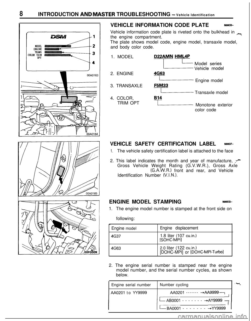
VEHICLE INFORMATION CODE PLATE
NOOCD-Vehicle information code plate is riveted onto the bulkhead in
rithe engine compartment.
The plate shows model code, engine model, transaxle model,
and body color code.
1. MODEL
2. ENGINE
3. TRANSAXLE
4. COLOR,
TRIM OPTD22AMN
HML4P
2 y$y:/e ‘f$$l
4G63
I Engine modelF5M33
y Transaxle model
B14
I Monotone exterior
color code
VEHICLE SAFETY CERTIFICATION LABELNOOCF-
1.The vehicle safety certification label is attached to the face
2. This label indicates the month and year of manufacture,
;eGross Vehicle Weight Rating (G.V.W.R.), Gross Axle
(G.A.W.R.) front and rear, and Vehicle
Identification Number
(V.I.N.).ENGINE MODEL STAMPING
NOOCG-
1.The engine model number is stamped at the front side on
following:
Engine model4637Engine displacement
1.8 liter (107 cu.in.)
[SOHC-MPI]
4G632.0 liter (122 cuin.)
[DOHC-MPI] or
[DOHC-MPI-Turbo]2. The engine serial number is stamped near the engine
model number, and the serial number cycles, as shown
below.Engine serial numberNumber cycling
AA0201 to w9999AA0201 ------- -*AA99997
I1 LAB0001 ------- +AY9999 : 1
I1 t-BAOOOI ------- +YY9999 ’ 1
‘-w
Page 20 of 1216
20INTRODUCTION AND MASTER TROUBLESHOOTING - Towing and Hoisting
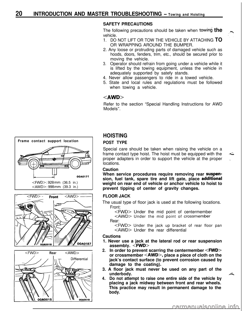
Frame contact support location
OOAOI 71
I
The following precautions should be taken when
towin the
vehicle.
1.DO NOT LIFT OR TOW THE VEHICLE BY ATTACHING TOOR WRAPPING AROUND THE BUMPER.
2. Any loose or protruding parts of damaged vehicle such as
hoods, doors, fenders, trim, etc., should be secured prior tomoving the vehicle.
3.Operator should refrain from going under a vehicle while it
is lifted by the towing equipment, unless the vehicle in
adequately supported by satefy stands.
4. Never allow passengers to ride in a towed vehicle.
5. State and local rules and regulations must be followed
when towing a vehicle.
Refer to the section “Special Handling Instructions for AWD
Models”.
HOISTING
POST TYPESpecial care should be taken when raising the vehicle on a
frame contact type hoist. The hoist must be equipped with the
proper adapters in order to support the vehicle at the proper
locations.Caution
When service procedures require removing rear sutpen-
sion, fuel tank, spare tire and lift gate, place addmonal
weight on rear end of vehicle or anchor vehicle to hoist to
prevent tipping of center of gravity changes.
FLOOR JACK
The usual type of floor jack is used at the following locations.
Front:
Rear:
Cautions
1. Never use a jack at the lateral rod or rear suspension
assembly.
2.In order to prevent scarring the centermember
jack’s contact surface (to prevent corrosion caused by
damage to the coating).
3. A floor jack must never be used on any part of the
underbody.
4.Do not attempt to raise one entire side of the vehicle byplacing a jack midway between front and rear wheels.
This practice may result in permanent damage to the
body.
Page 24 of 1216
24 INTRODUCTION AND MASTER TROUBLESHOOTING - fSo%k%:~~it’ndrU~ionsREAR WHEEL MEASUREMENTS
After placing the rear wheels on the brake tester, follow the
same procedures as for the front wheel measurements.
,’
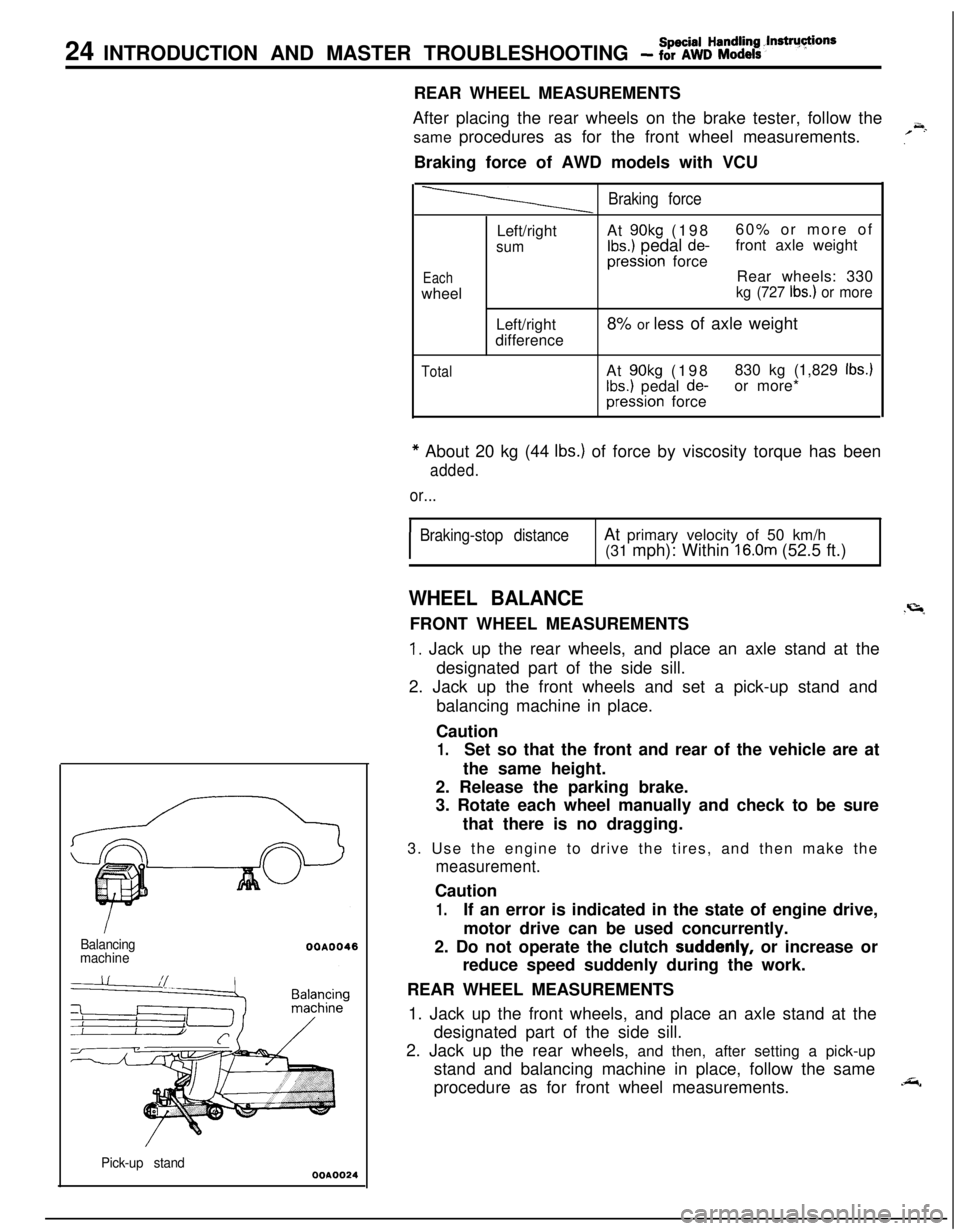
~.Braking force of AWD models with VCU
Balancing
machine
Pick-up stand
WA0024
Braking force
EachwheelLeft/right
sumLeft/right
differenceAt
90kg (19860% or more ofIbs.) pedal de-front axle weightpression force
Rear wheels: 330
kg (727 Ibs.) or more8% or less of axle weight
TotalAt 90kg (198830 kg (1,829 Ibs.)
Ibs.) pedal de-or more*pression force
* About 20 kg (44 Ibs.) of force by viscosity torque has been
added.
or...
I
Braking-stop distanceAt primary velocity of 50 km/h
(31 mph): Within 16.0m (52.5 ft.)
WHEEL BALANCE.r=lFRONT WHEEL MEASUREMENTS
1. Jack up the rear wheels, and place an axle stand at the
designated part of the side sill.
2. Jack up the front wheels and set a pick-up stand and
balancing machine in place.
Caution
1.Set so that the front and rear of the vehicle are at
the same height.
2. Release the parking brake.
3. Rotate each wheel manually and check to be sure
that there is no dragging.
3. Use the engine to drive the tires, and then make the
measurement.Caution
1.If an error is indicated in the state of engine drive,
motor drive can be used concurrently.
2. Do not operate the clutch
suddenly, or increase or
reduce speed suddenly during the work.
REAR WHEEL MEASUREMENTS
1. Jack up the front wheels, and place an axle stand at the
designated part of the side sill.
2. Jack up the rear wheels, and then, after setting a pick-up
stand and balancing machine in place, follow the same
procedure as for front wheel measurements.
.&,
Page 25 of 1216
INTRODUCTION AND MASTER TROUBLESHOOTING - :;k%ii::& and25
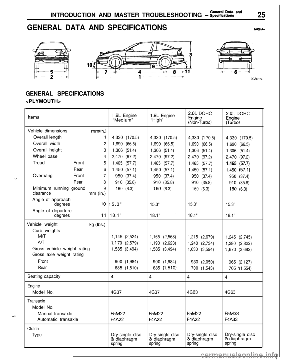
GENERAL DATA AND SPECIFICATIONSNOOHA-
OOAOl59
GENERAL SPECIFICATIONS
z-
A-l
.8L Engine1.8L Engine2.0L DOHC2.0L DOHCItems“Medium”“High”~%n?urbo):Tz%$
Vehicle dimensions
mm(in.)Overall length
14,330(170.5)4,330(170.5)4,330(I 70.5)4,330(170.5)Overall width
21,690(66.5)1,690(66.5)
1,690
(66.5)
1,690(66.5)Overall height
31,306(51.4)1,306(51.4)1,306(51.4)
1,306(51.4)Wheel base
4
2,470(97.2)2,470(97.2)2,470(97.2)2,470(97.2)Tread Front
5
1,465(57.7)
1,465(57.7)
1,465
(57.7)1,465(57.7)
Rear6
1,450(57.1)1,450(57.1)1,450(57.1)1,450(57:l i
Overhang Front
7950(37.4)950(37.4)950(37.4)
950(37.4)
Rear
8
910(35.8)910(35.8)910(35.8)910(35.8)Minimum running ground
9
160(6.3)160(6.3)
160(6.3)160(6.3)clearancemm (in.)
Angle of approach
degrees10 15.3”15.3”15.3”
15.3”Angle of departure
degrees11 18.1”
18.1” ’18.1“
18.1”Vehicle weight
kg (Ibs.)
Curb weights
M/T
1,145(2,524)
1,165(2,568)
1,215
(2,679)
1,245(2,745)
AIT1 ,I 70(2,579)
1,190(2,623)
1,240
(2,734)
1,280(2,822)Gross vehicle weight rating
1,585(3,494)1,585(3,494)
1,630
(3,594)‘I ,670(3,682)Gross axle weight rating
Front
900(1,984)900(1,984)930(2,050)965(2,127)
Rear
685(1,510)685(1,510)
700
(1,543)705‘(1,554)Seating capacity
4
444
EngineModel No.
4G3746374G634G63
TransaxleModel No.
Manual transaxle
F5M22F5M22F5M22F5M33Automatic transaxle
F4A22F4A22F4A22F4A33
Clutch
TypeDry-single discDry-single discDry-single discDry-single disc& diaphragm& diaphragm& diaphragm& diaphragm
springspringspringspring
Page 26 of 1216
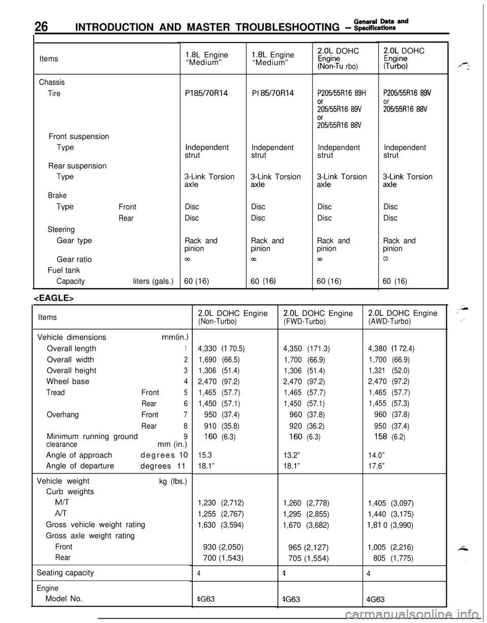
26INTRODUCTION AND MASTER TROUBLESHOOTING - :;:%:a=and
Items
Chassis
TireFront suspension
TypeRear suspension
We
Brake
Type
SteeringGear typeFront
RearGear ratio
Fuel tank
Capacityliters (gals.)
1.8L Engine
“Medium”Pl85/70R14
PI 85/70Rl4
Independent
strut
Independentstrut
3l\Fk Torsion&k-k Torsion
Disc
DiscDisc
Disc
Rack and
pinion
03
Rack and
pinion
cn60 (16)
60
(16)
ItemsVehicle dimensions
mm(in.)Overall length
1Overall width
2Overall height
3Wheel base
4
TreadFront5
Rear6
OverhangFront7
Rear8Minimum running ground
9
clearancemm (in.)
Angle of approachdegrees
10Angle of departure
degrees 11
Vehicle weight
kg (Ibs.)Curb weightsMiT
Al-rGross vehicle weight rating
Gross axle weight rating
Front
RearSeating capacity
EngineModel No.
1.8L Engine
“Medium”2.0L DOHC
Kr%n?u rbo)
P205/55Rl6 89H
;;5/55R16 89V%55R16
88V
Independentstrut
zx;;k Torsion
Disc
Disc
Rack and
pinion
co60 (16)
2.0L DOHC
#b”;
P205/55Rl6 89
or
205155R16 88V
Independentstrut
3Lnk Torsion
Disc
Disc
Rack and
pinion
co
60 (16)
2.0L DOHC Engine(Non-Turbo)
4,330(I 70.5)
1,690(66.5)
1,306(51.4)
2,470(97.2)
1,465(57.7)
1,450(57.1)
950(37.4)
910(35.8)
160(6.3)
15.3
18.1”
1,230 (2,712)
1,255 (2,767)
1,630 (3,594)930 (2,050)
700 (1,543)
4
4G63
2.0L DOHC Engine
(FWD-Turbo)
4,350(171.3)
1,700(66.9)
1,306(51.4)
2,470(97.2)
1,465(57.7)
1,450(57.1)
960(37.8)
920(36.2)
160(6.3)
13.2”
18.1”
1,260 (2,778)
1,295 (2,855)
1,670 (3,682)965 (2,127)
705 (1,554)
1
4G63
2.0L DOHC Engine
(AWD-Turbo)
4,380(I 72.4)
1,700(66.9)
1,321(52.0)
2,470(97.2)
1,465(57.7)
1,455(57.3)
960(37.8)
950(37.4)
158(6.2)
14.0”
17.6”
1,405 (3,097)
1,440 (3,175)
I,81 0 (3,990)
1,005 (2,216)
805 (1,775)
4
4G63
Page 65 of 1216
FRONT SUSPENSION - Drive Shaft247Pry bar
13E526
12RO426Cotter pin
/
/HubllR0015
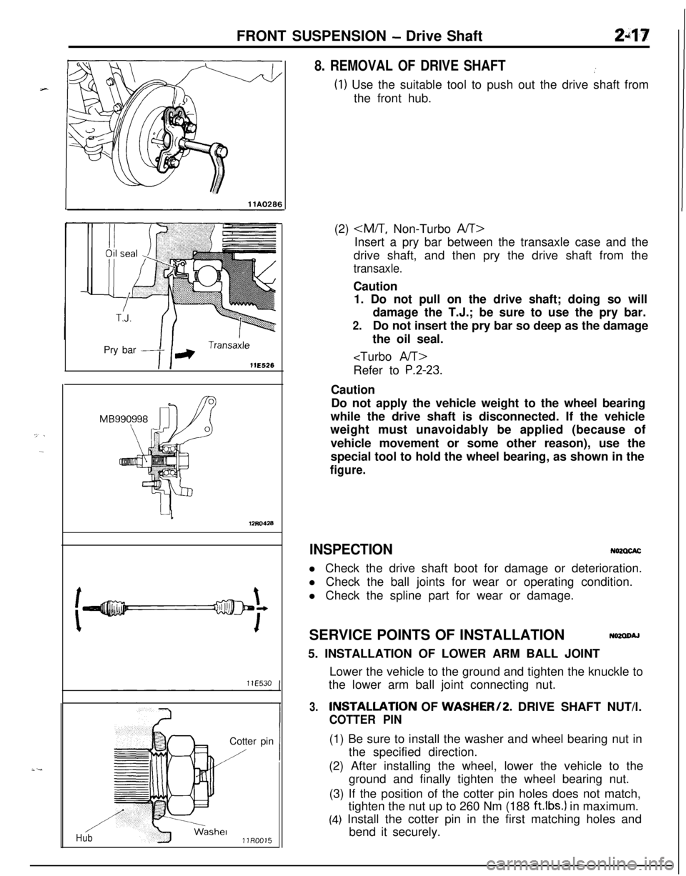
8. REMOVAL OF DRIVE SHAFT.’
(1) Use the suitable tool to push out the drive shaft from
the front hub.
(2)
Insert a pry bar between the transaxle case and the
drive shaft, and then pry the drive shaft from the
transaxle.Caution
1. Do not pull on the drive shaft; doing so will
damage the T.J.; be sure to use the pry bar.
2.Do not insert the pry bar so deep as the damage
the oil seal.
P.2-23.Caution
Do not apply the vehicle weight to the wheel bearing
while the drive shaft is disconnected. If the vehicle
weight must unavoidably be applied (because of
vehicle movement or some other reason), use the
special tool to hold the wheel bearing, as shown in the
figure.
INSPECTIONN62CXACl Check the drive shaft boot for damage or deterioration.
l Check the ball joints for wear or operating condition.
l Check the spline part for wear or damage.
SERVICE POINTS OF INSTALLATION
N62aoAJ5. INSTALLATION OF LOWER ARM BALL JOINT
Lower the vehicle to the ground and tighten the knuckle to
the lower arm ball joint connecting nut.
3.INSTALLATlON OF WASHER/2. DRIVE SHAFT NUT/l.
COTTER PIN(1) Be sure to install the washer and wheel bearing nut in
the specified direction.
(2) After installing the wheel, lower the vehicle to the
ground and finally tighten the wheel bearing nut.
(3) If the position of the cotter pin holes does not match,
tighten the nut up to 260 Nm (188
ft.lbs.) in maximum.
(4) Install the cotter pin in the first matching holes and
bend it securely.
Page 314 of 1216
50-65 Nm*36-47 ft.lbs.*
9-30ENGINE - Engine Roll Stopper
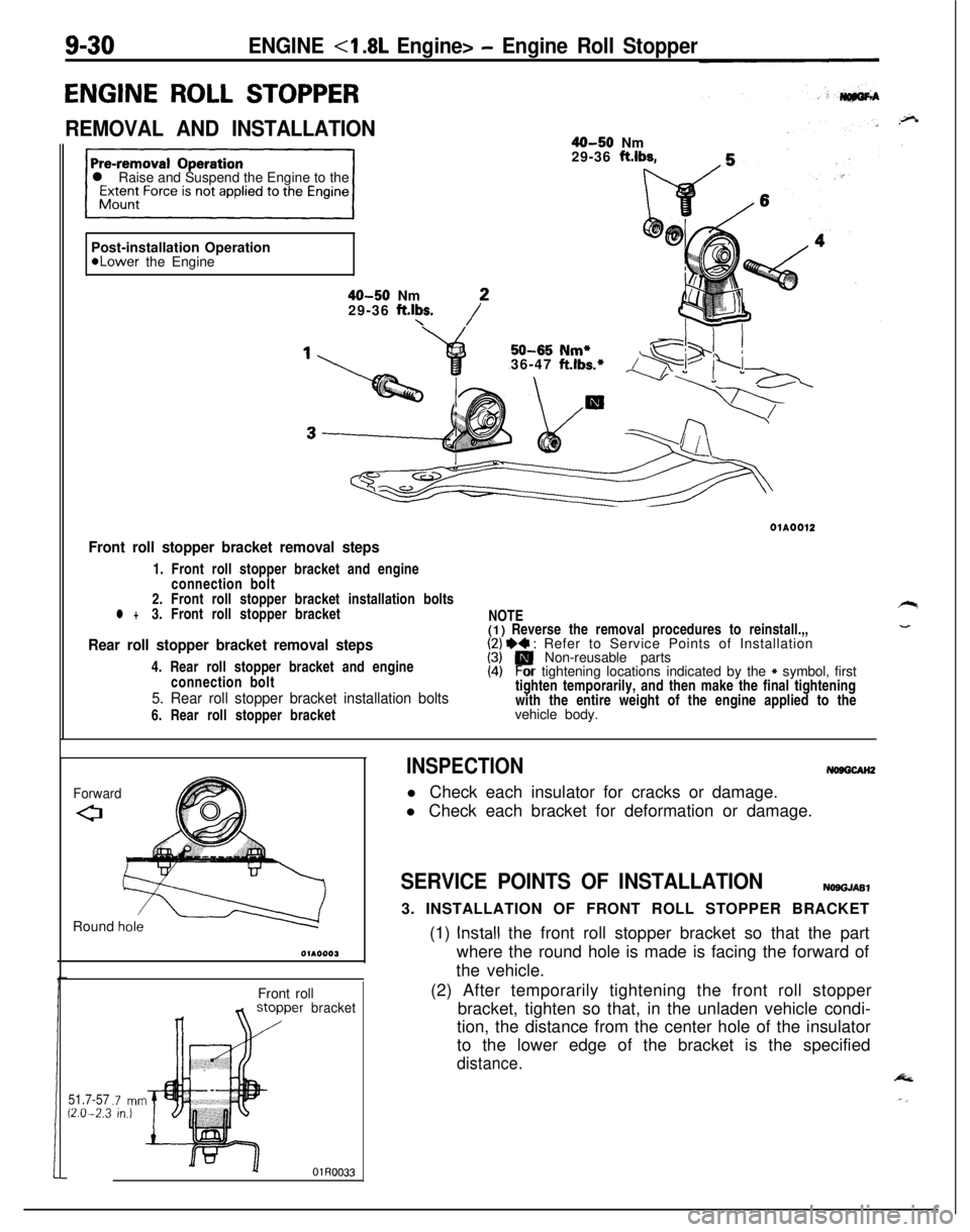
ENGINE ROLL STOPPER
REMOVAL AND INSTALLATION40-50 Nm
29-36 ft.lbs.
l Raise and Suspend the Engine to the
Post-installation Operation
*Lower the Engine
40-50 Nm
29-36 ft.lbs.\/*01A0012
Front roll stopper bracket removal steps1. Front roll stopper bracket and engine
connection bolt
2. Front roll stopper bracket installation bolts
l +3. Front roll stopper bracket
Rear roll stopper bracket removal steps4. Rear roll stopper bracket and engine
connection bolt
5. Rear roll stopper bracket installation bolts6. Rear roll stopper bracketNOTE
(1) Reverse the removal procedures to reinstall.,,
I;/ I)+ : Refer to Service Points of Installation
Non-reusable parts
(4)Por tightening locations indicated by the * symbol, first
tighten temporarily, and then make the final tightening
with the entire weight of the engine applied to the
vehicle body.
ForwardRound
h&Front roll
51.7-5712.0-2.3.7 mnin.)
bracket
INSPECTIONNosGcAH2l Check each insulator for cracks or damage.
l Check each bracket for deformation or damage.
SERVICE POINTS OF INSTALLATIONNOSGJASl3. INSTALLATION OF FRONT ROLL STOPPER BRACKET
(1)
Install the front roll stopper bracket so that the part
where the round hole is made is facing the forward of
the vehicle.
(2) After temporarily tightening the front roll stopper
bracket, tighten so that, in the unladen vehicle condi-
tion, the distance from the center hole of the insulator
to the lower edge of the bracket is the specified
distance.
Page 316 of 1216
9-32ENGINE <1.8L Engine> - Engine Assembly35-45 Nm
25-33
ft.lbs.
25 31\5$M35 Nm
36-47 ft.lbs.
OlAO56429-36
ft.lbs.
3&40 Nm
22-29 ft.lbs.
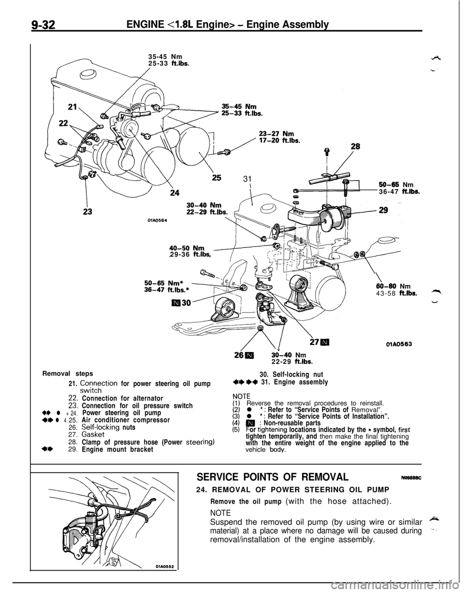
Removal steps
21.
zztTtion for power steering oil pump30. Self-locking nut4e +4 31. Engine assembly
+e l + 24.*I)l 425.
26.27.
28.
4+29.
\60-80 Nm
43-58 ft.lbs.
OlAO563Connection for alternator
Connection for oil pressure switch
Power steering oil pump
Air conditioner compressor
palffz,cklng nuts
Clamp of pressure hose (Power
steelEngine mount bracket
ITEReverse the removal procedures to reinstall.
l *
: Refer to “Service Points of Removal”.
l * : Refer to “Service Points of Installation”.
P; Non-reusable parts
or ttghtening locations indicated by the * symbol, firs1tighten temporarily, and then make the final tightening
with the entire weight of the engine applied to the
vehicle
body.
t
SERVICE POINTS OF REMOVALNogs6SC24. REMOVAL OF POWER STEERING OIL PUMP
Remove the oil pump (with the hose attached).
NOTESuspend the removed oil pump (by using wire or similar
material) at a place where no damage will be caused duringremoval/installation of the engine assembly.
Page 363 of 1216
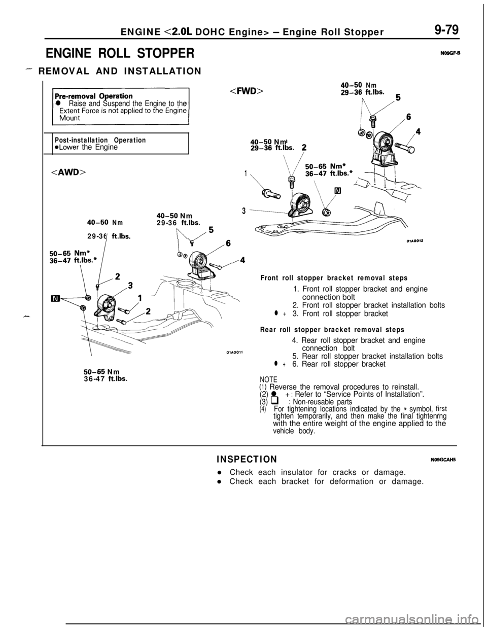
ENGINE <2.0L DOHC Engine> - Engine Roll Stopper
ENGINE ROLL STOPPER
- REMOVAL AND INSTALLATION
9-79
NOSGF-B
X
l Raise and Suspend the Engine to the
40-50Nm29-36ft.lbs.
Post-installation Operation
@Lower the Engine40-50 Nm
1
40-50 Nm3
40-50Nm29-36ft.lbs.
29-36ft.lbs.In/5
/4
\
50-65 Nm
36-47 ftlbs.
Front roll stopper bracket removal steps
1. Front roll stopper bracket and engineconnection bolt
2. Front roll stopper bracket installation bolts
l +3. Front roll stopper bracket
Rear roll stopper bracket removal steps
4. Rear roll stopper bracket and engine
connection bolt
5. Rear roll stopper bracket installation bolts
l +6. Rear roll stopper bracket
NOTE(I) Reverse the removal procedures to reinstall.
(2) l + : Refer to “Service Points of Installation”.(3) q : Non-reusable parts(4)For tightening locations indicated by the * symbol, fjrsttighten temporarily, and then make the final tightenrngwith the entire weight of the engine applied to the
vehicle body.
INSPECTIONNOSGCAHSl Check each insulator for cracks or damage.
l Check each bracket for deformation or damage.
Page 366 of 1216
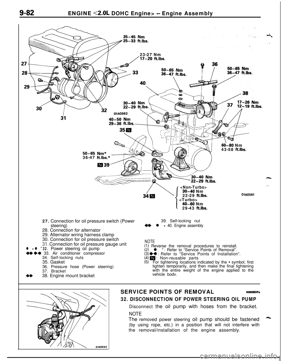
9-82ENGINE <2.0L DOHC Engine> - Engine Assembly
23-27 Nm
/17-20 ftlbs.
60-60 Nm
43-58 ft.lbs.50-65 Nm*36-47 ft.lbs.*27. Connection for oil pressure switch (Power
steering)28. Connection for alternator
29. Alternator wiring harness clamp
30. Connection for oil pressure switch
31, Connection for oil pressure gauge unitl + l * 32.Power steering oil pump+9 ~~ 33. Air conditioner compressor
34. Self-locking nuts
35. Gasket
36. Pressure hose (Power steering)
37. Bracket
4*38. Engine mount bracket
22-29 ftlbs.
.--
OlAO561
1
I40-60 Nm
29-43 ft.lbs.39. Self-locking nut
+e l + 40. Engine assembly
NOTE(I) Reverse the removal procedures to reinstall.(2) l * : Refer to “Service Points of Removal”.(3) I)+ : Refer to “Service Points of Installation”.(4) m : Non-reusable parts(5)For tightening locations indicated by the * symbol, first
tighten temporarily, and then make the final tightening
with the entire weight of the engine applied to the
vehicle bodv.
SERVICE POINTS OF REMOVALNOSSBDFa
32. DISCONNECTION OF POWER STEERING OIL PUMPDisconnect the oil pump with hoses from the bracket.
NOTEThe removed power steering oil pump should be fastened
A(by using rope, etc.) in a position that will not interfere with
the removal/installation of the engine assembly.