Rear suspension MITSUBISHI ECLIPSE 1991 Owner's Guide
[x] Cancel search | Manufacturer: MITSUBISHI, Model Year: 1991, Model line: ECLIPSE, Model: MITSUBISHI ECLIPSE 1991Pages: 1216, PDF Size: 67.42 MB
Page 626 of 1216
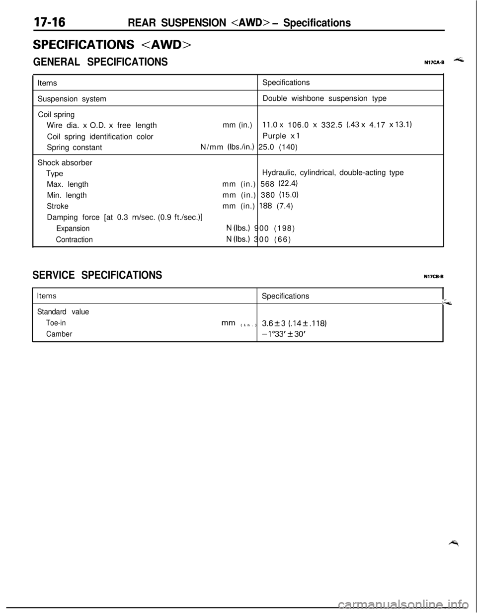
17-16REAR SUSPENSION
SPECIFICATIONS
GENERAL SPECIFICATIONSNl’ICA-B jG
ItemsSpecifications
Suspension systemDouble wishbone suspension type
Coil spring
Wire dia. x O.D.
x free lengthmm (in.)11.0 x 106.0 x 332.5 (.43 x 4.17 x 13.1)Coil spring identification colorPurple
x 1Spring constantN/mm
(Ibs./in.) 25.0 (140)
Shock absorber
TypeHydraulic, cylindrical, double-acting type
Max. lengthmm (in.) 568
(22.4)Min. lengthmm (in.) 380
(15.0)
Strokemm (in.) 188 (7.4)
Damping force [at 0.3 m/set. (0.9
ft./set.)]
ExpansionN (Ibs.) 900 (198)
ContractionN (Ibs.) 300 (66)
SERVICE SPECIFICATIONS
Items
Standard value
Toe-in
CamberSpecificationsmm (in.) 3.6+3 (.14f.l18)
-1"33'f30'
Nl7CEB
:&
Page 627 of 1216
REAR SUSPENSION
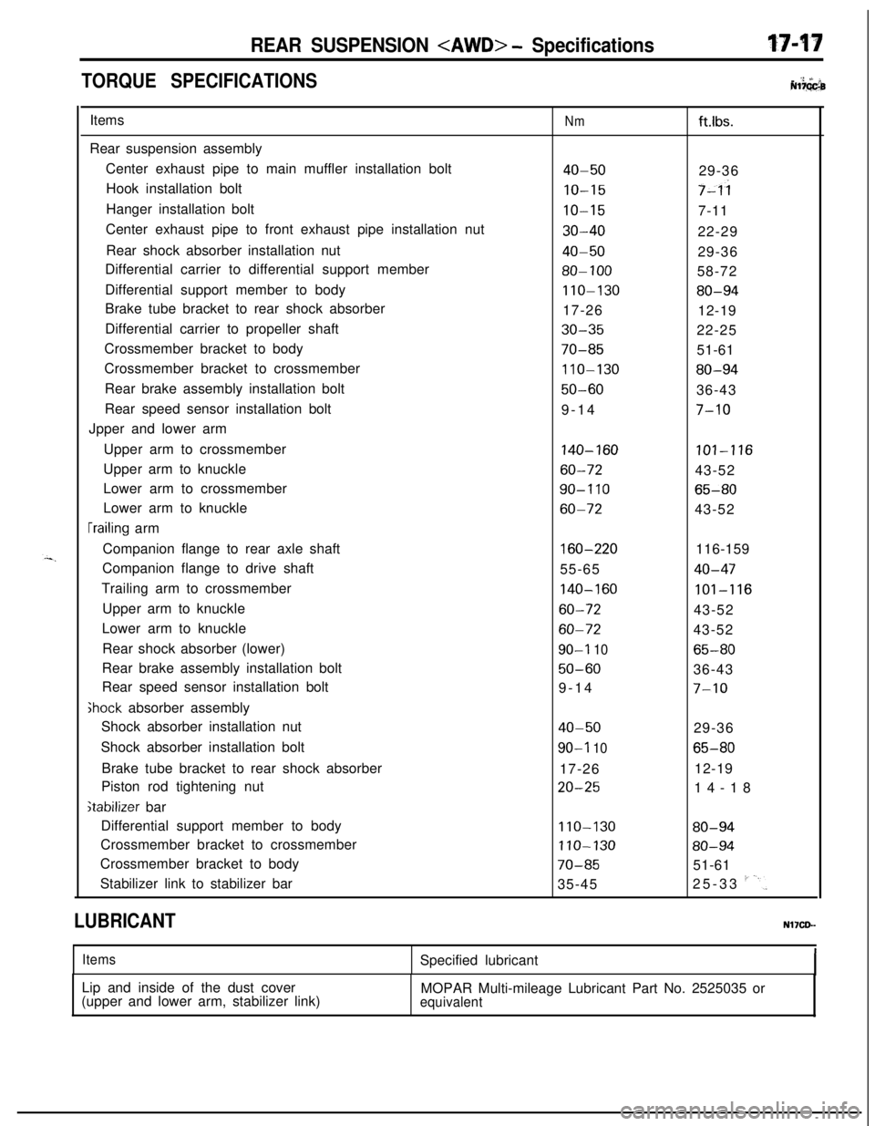
TORQUE SPECIFICATIONS. ‘2 +’ iiNl?GGbItems
Rear suspension assembly
Center exhaust pipe to main muffler installation bolt
Hook installation bolt
Hanger installation bolt
Center exhaust pipe to front exhaust pipe installation nut
Rear shock absorber installation nut
Differential carrier to differential support member
Differential support member to body
Brake tube bracket to rear shock absorber
Differential carrier to propeller shaft
Crossmember bracket to body
Crossmember bracket to crossmember
Rear brake assembly installation bolt
Rear speed sensor installation bolt
Jpper and lower arm
Upper arm to crossmember
Upper arm to knuckle
Lower arm to crossmember
Lower arm to knuckle
[railing arm
Companion flange to rear axle shaft
Companion flange to drive shaft
Trailing arm to crossmember
Upper arm to knuckle
Lower arm to knuckle
Rear shock absorber (lower)
Rear brake assembly installation bolt
Rear speed sensor installation bolt
Ghock absorber assembly
Shock absorber installation nut
Shock absorber installation bolt
Brake tube bracket to rear shock absorber
Piston rod tightening nut
stabilizer bar
Differential support member to body
Crossmember bracket to crossmember
Crossmember bracket to body
Stabilizer link to stabilizer bar
Nmft.lbs.
40-5029-36
IO-157-ii
IO-157-11
30-4022-29
40-5029-36
80-10058-72
110-13080-9417-26
12-19
30-3522-25
70-8551-61
110-13080-94
50-6036-43
9-14
7-10
140-160101-116
60-7243-52
90-I 1065-80
60-7243-52
160-220116-159
55-65
40-47
140-160101-116
60-7243-52
60-7243-52
90-I 1065-80
50-6036-43
9-14
7-10
40-5029-36
90-l 1065-8017-2612-19
20-2514-18
110-13080-94
110-13080-94
70-8551-61
35-4525-33
I'-'.
LUBRICANTNl’ICD-
ItemsSpecified lubricant
Lip and inside of the dust cover
(upper and lower arm, stabilizer link)MOPAR Multi-mileage Lubricant Part No. 2525035 or
equivalent
Page 628 of 1216

17-18REAR SUSPENSION
SPECIAL TOOLSNl’IDA-BTnnl
NtlmherNameI Use
Axle shaft puller
Lower armbushing
Page 629 of 1216

REAR SUSPENSION
pnng compressor
TROUBLESHOOTINGNIlEA-6
Symptom
Squeaks or other
abnormal noiseProbable causeRemedyLoose rear suspension installation bolts and nuts Retighten
Malfunction of shock absorber
Worn bushings
Replace
Upper arms and/or lower arms deformed or
damaged
Poor ride
Body tiltingTrailing arms deformed or damaged
Crossmember deformed or damagedExcessive tire inflation pressure
Malfunction of shock absorber
Weak or broken springs
Stabilizer bar and/or stabilizer link deformed or
damaged
Weak or deteriorated bushings
Weak or broken springs
Upper arms and/or lower arms deformed or
damaged
Trailing arms deformed or damaged
Crossmember deformed or damagedAdjust the pressure
Replace
Replace
Page 630 of 1216
17-20REAR SUSPENSION
12R0556-- Upper arm
(L.H.)
12A0081
SERVICE ADJUSTMENT PROCEDURES
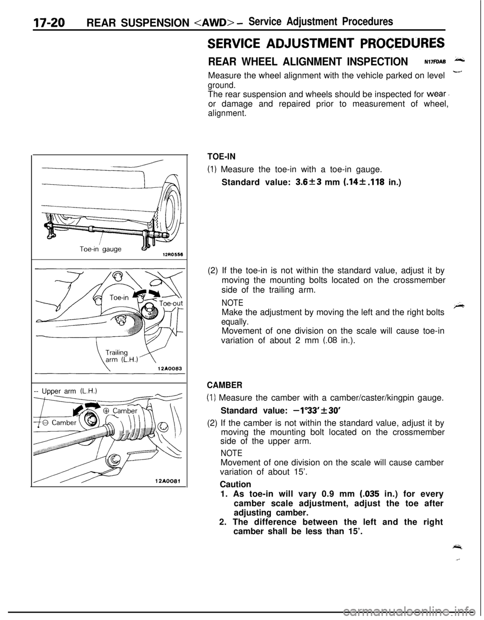
REAR WHEEL ALIGNMENT INSPECTIONN17FDAB is.Measure the wheel alignment with the vehicle parked on level
--’
ground.The rear suspension and wheels should be inspected for
wear’or damage and repaired prior to measurement of wheel,
alignment.
TOE-IN
(1) Measure the toe-in with a toe-in gauge.
Standard value:
3.6f3 mm (.14+ .I18 in.)
(2) If the toe-in is not within the standard value, adjust it by
moving the mounting bolts located on the crossmember
side of the trailing arm.
NOTEMake the adjustment by moving the left and the right bolts
r;hr
equally.Movement of one division on the scale will cause toe-in
variation of about 2 mm
(.08 in.).
CAMBER
(1) Measure the camber with a camber/caster/kingpin gauge.
Standard value:
-1”33’f30’(2) If the camber is not within the standard value, adjust it by
moving the mounting bolt located on the crossmember
side of the upper arm.
NOTEMovement of one division on the scale will cause camber
variation of about 15’.
Caution
1. As toe-in will vary 0.9 mm
(.035 in.) for every
camber scale adjustment, adjust the toe after
adjusting camber.
2. The difference between the left and the right
camber shall be less than 15’.
Page 631 of 1216
REAR SUSPENSION
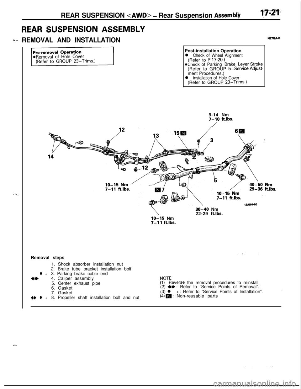
REAR SUSPENSION ASSEMBLY
5.REMOVAL AND INSTALLATIONN17GA-BPost-installation Operation
l Check of Wheel Alignment(Refer to P.17-20.)@Check of ParkingBrakeLever Stroke
(Refer to GROUP 5-Service Adjust
ment Procedures.)
l installation of Hole Cover(Refer to GROUP 23-Trims.)9-14 Nm
7-10 ft.lbs.
/
12AO640
\lo-15 Nm7-l 1 ft.lbs.
30-40 Nm
22-29 ft.lbs.
Removal steps
1. Shock absorber installation nut
2. Brake tube bracket installation bolt
l +3. Parking brake cable end
**4. Caliper assembly
5. Center exhaust pipe!rEeverse the removal procedures to reinstall.
6. Gasket(2) 4e: Refer to “Service Points of Removal”.
7. Gasket(3) l + : Refer to “Service Points of Installation”.’+I)
l +8. Propeller shaft installation bolt and nut(4) m : Non-reusable parts
Page 632 of 1216
 30-35 Nm,22-25 ftlbs.-- -- .-._--.I
17-26 Nm
t
12-19 ft.lbs.\
\
llO-i30 Nm80-94 ft.lbs.
70-85’")
17-22REAR SUSPENSION
40-50 Nm
129-36 ft.lbs./
80-100 Nm
58-72 fiq T
i) 30-35 Nm,22-25 ftlbs.-- -- .-._--.I
17-26 Nm
t
12-19 ft.lbs.\
\
llO-i30 Nm80-94 ft.lbs.
70-85’ Nm51-61ftlbs.
I50-60Nm
36-43 ft.lbs.
70-85Nm51-61ft.lbs.80-94ftlbs.
12AO641Removal steps
+*9. Self locking nut
10. Differential support member
11. Crossmember bracket
4*12. Parking brake cable and rear speed sensorinstallation bolt
13. Cable band
4*14. Rear speed sensor connector
ABS15. O-ring16. Rear suspension assembly
NOTE(1) Reverse the removal procedures to reinstall.
(2)
+e : Refer to “Service Points of Removal”.
(3) l : Refer to “Service Points of Installation”.
(4) a : Non-reusable parts
Page 633 of 1216
REAR SUSPENSION
14AO520
12AOlOQ
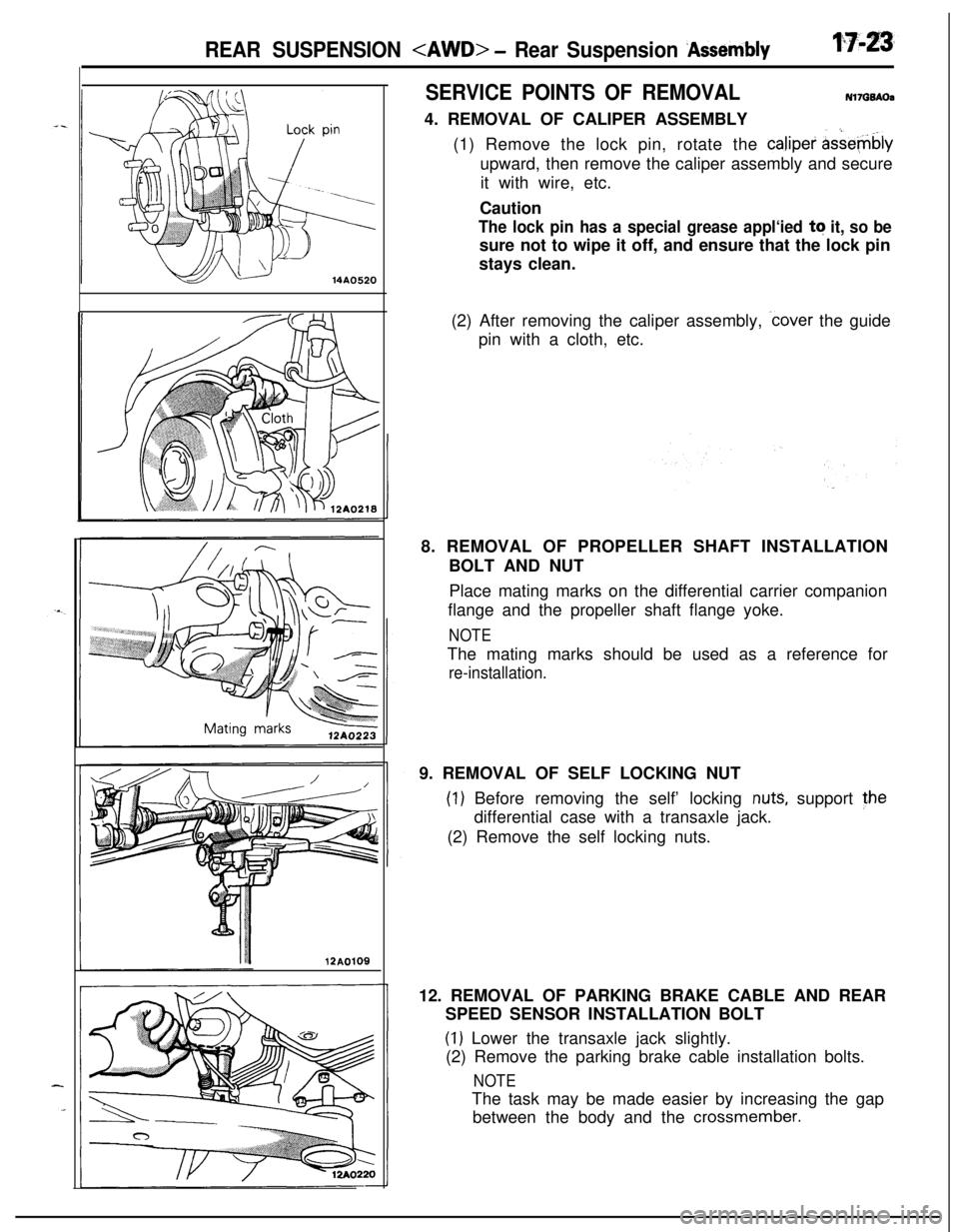
SERVICE POINTS OF REMOVALN17GQAOa4. REMOVAL OF CALIPER ASSEMBLY
(1) Remove the lock pin, rotate the calipei
&&e-@blyupward, then remove the caliper assembly and secure
it with wire, etc.
Caution
The lock pin has a special grease appl‘ied tq it, so besure not to wipe it off, and ensure that the lock pin
stays clean.
(2) After removing the caliper assembly,
.cover the guide
pin with a cloth, etc.
8. REMOVAL OF PROPELLER SHAFT INSTALLATION
BOLT AND NUT
Place mating marks on the differential carrier companion
flange and the propeller shaft flange yoke.
NOTEThe mating marks should be used as a reference for
re-installation.9. REMOVAL OF SELF LOCKING NUT
(1) Before removing the self’ locking nuts, support the
differential case with a transaxle jack.
(2) Remove the self locking nuts.
12. REMOVAL OF PARKING BRAKE CABLE AND REAR
SPEED SENSOR INSTALLATION BOLT
(1) Lower the transaxle jack slightly.
(2) Remove the parking brake cable installation bolts.
NOTEThe task may be made easier by increasing the gap
between the body and the
crossmember.
Page 634 of 1216
17-24REAR SUSPENSION
1
II
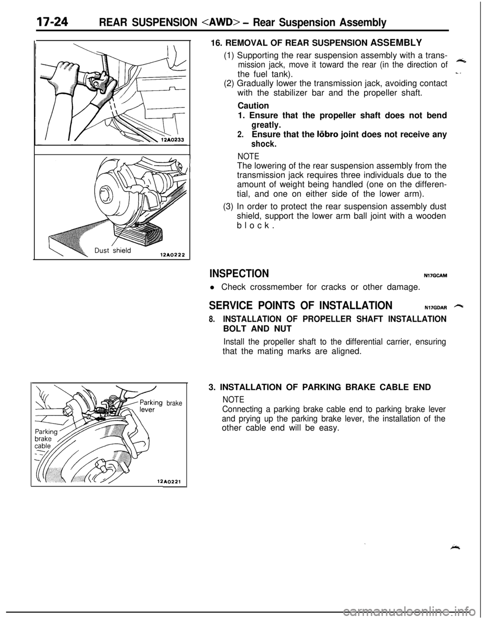
brakeA022116. REMOVAL OF REAR SUSPENSION ASSEMBLY
(1) Supporting the rear suspension assembly with a trans-
mission jack, move it toward the rear (in the direction of
wtthe fuel tank).
c1(2) Gradually lower the transmission jack, avoiding contact
with the stabilizer bar and the propeller shaft.
Caution
1. Ensure that the propeller shaft does not bend
greatly.
2.Ensure that the liibro joint does not receive any
shock.
NOTEThe lowering of the rear suspension assembly from the
transmission jack requires three individuals due to the
amount of weight being handled (one on the differen-
tial, and one on either side of the lower arm).
(3) In order to protect the rear suspension assembly dust
shield, support the lower arm ball joint with a wooden
block.
INSPECTIONNl7GCAMl Check crossmember for cracks or other damage.
SERVICE POINTS OF INSTALLATIONN17GOAR -
8.INSTALLATION OF PROPELLER SHAFT INSTALLATIONBOLT AND NUT
Install the propeller shaft to the differential carrier, ensuringthat the mating marks are aligned.
3. INSTALLATION OF PARKING BRAKE CABLE END
NOTE
Connecting a parking brake cable end to parking brake lever
and prying up the parking brake lever, the installation of theother cable end will be easy.
’ice,
Page 635 of 1216
REAR SUSPENSION
UPPER AND LOWER ARM
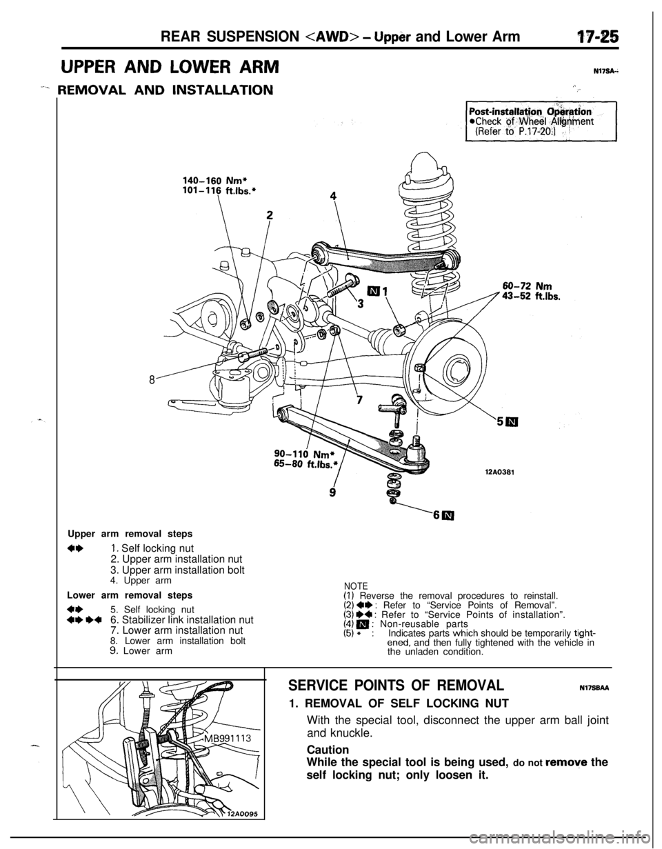
-. REMOVAL AND INSTALLATION
140-160 Nm+/cc?!4
,.1;’
Post-installa~o~ O&N tion-1
8
a12A0381Upper arm removal steps
4+1. Self locking nut
2. Upper arm installation nut
3. Upper arm installation bolt
4. Upper arm
Lower arm removal steps
4*5. Self locking nut+I) H6. Stabilizer link installation nut
7. Lower arm installation nut
8. Lower arm installation bolt
9. Lower arm
NOTE(I) Reverse the removal procedures to reinstall.(2) ++ : Refer to “Service Points of Removal”.(3) e+ : Refer to “Service Points of installation”.[;I p i Non-reusable parts
Indicates parts which should be temporarily tight-
ened, and then fully tightened with the vehicle in
the unladen condition.
SERVICE POINTS OF REMOVALNl7S0AA1. REMOVAL OF SELF LOCKING NUT
With the special tool, disconnect the upper arm ball joint
and knuckle.
Caution
While the special tool is being used, do not remove the
self locking nut; only loosen it.