Rear suspension MITSUBISHI ECLIPSE 1991 User Guide
[x] Cancel search | Manufacturer: MITSUBISHI, Model Year: 1991, Model line: ECLIPSE, Model: MITSUBISHI ECLIPSE 1991Pages: 1216, PDF Size: 67.42 MB
Page 87 of 1216
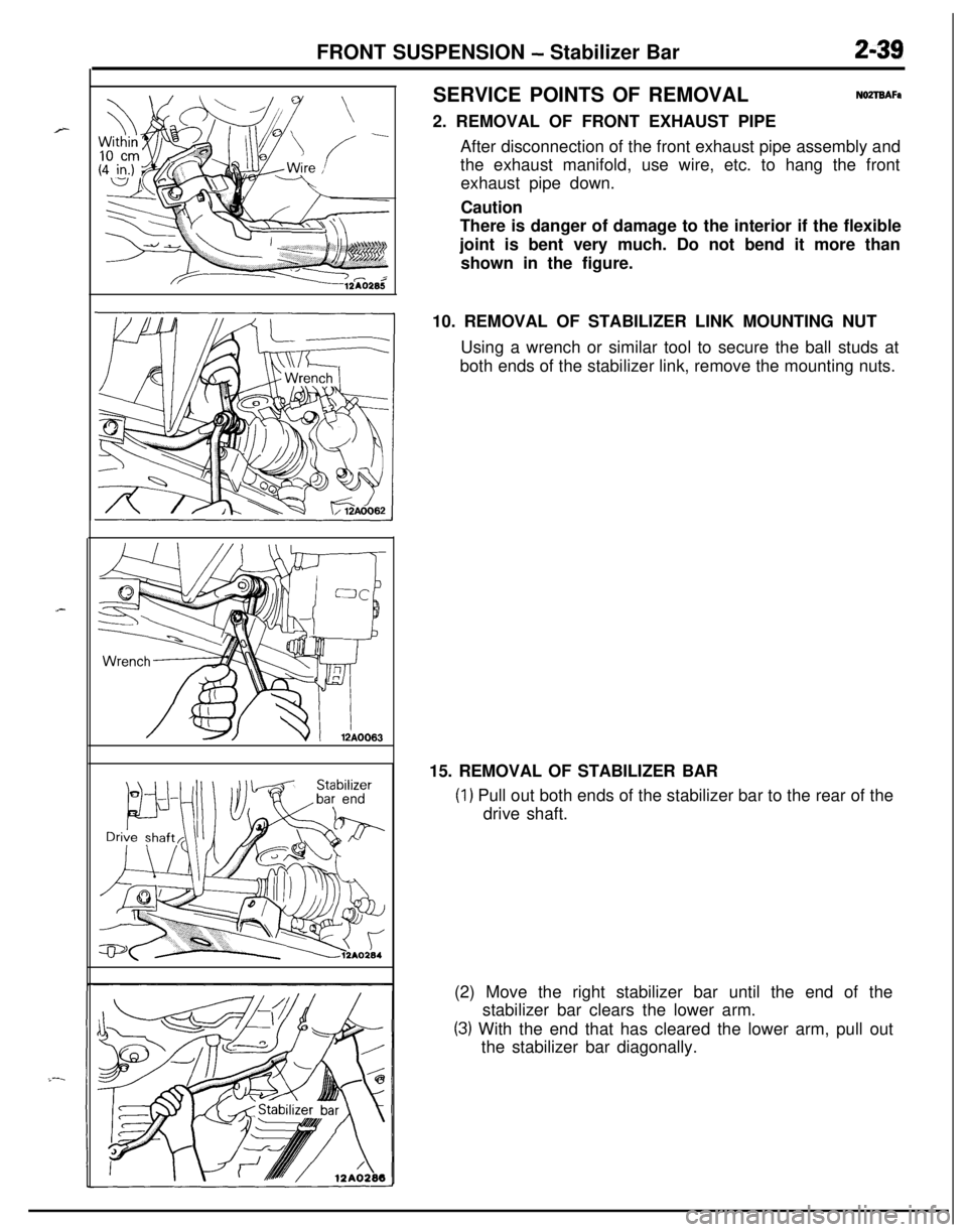
FRONT SUSPENSION - Stabilizer Bar2-39SERVICE POINTS OF REMOVAL
NOZTBAFa2. REMOVAL OF FRONT EXHAUST PIPE
After disconnection of the front exhaust pipe assembly and
the exhaust manifold, use wire, etc. to hang the front
exhaust pipe down.
Caution
There is danger of damage to the interior if the flexible
joint is bent very much. Do not bend it more than
shown in the figure.
10. REMOVAL OF STABILIZER LINK MOUNTING NUT
Using a wrench or similar tool to secure the ball studs at
both ends of the stabilizer link, remove the mounting nuts.
15. REMOVAL OF STABILIZER BAR
(1) Pull out both ends of the stabilizer bar to the rear of the
drive shaft.
(2) Move the right stabilizer bar until the end of the
stabilizer bar clears the lower arm.
(3) With the end that has cleared the lower arm, pull out
the stabilizer bar diagonally.
Page 92 of 1216
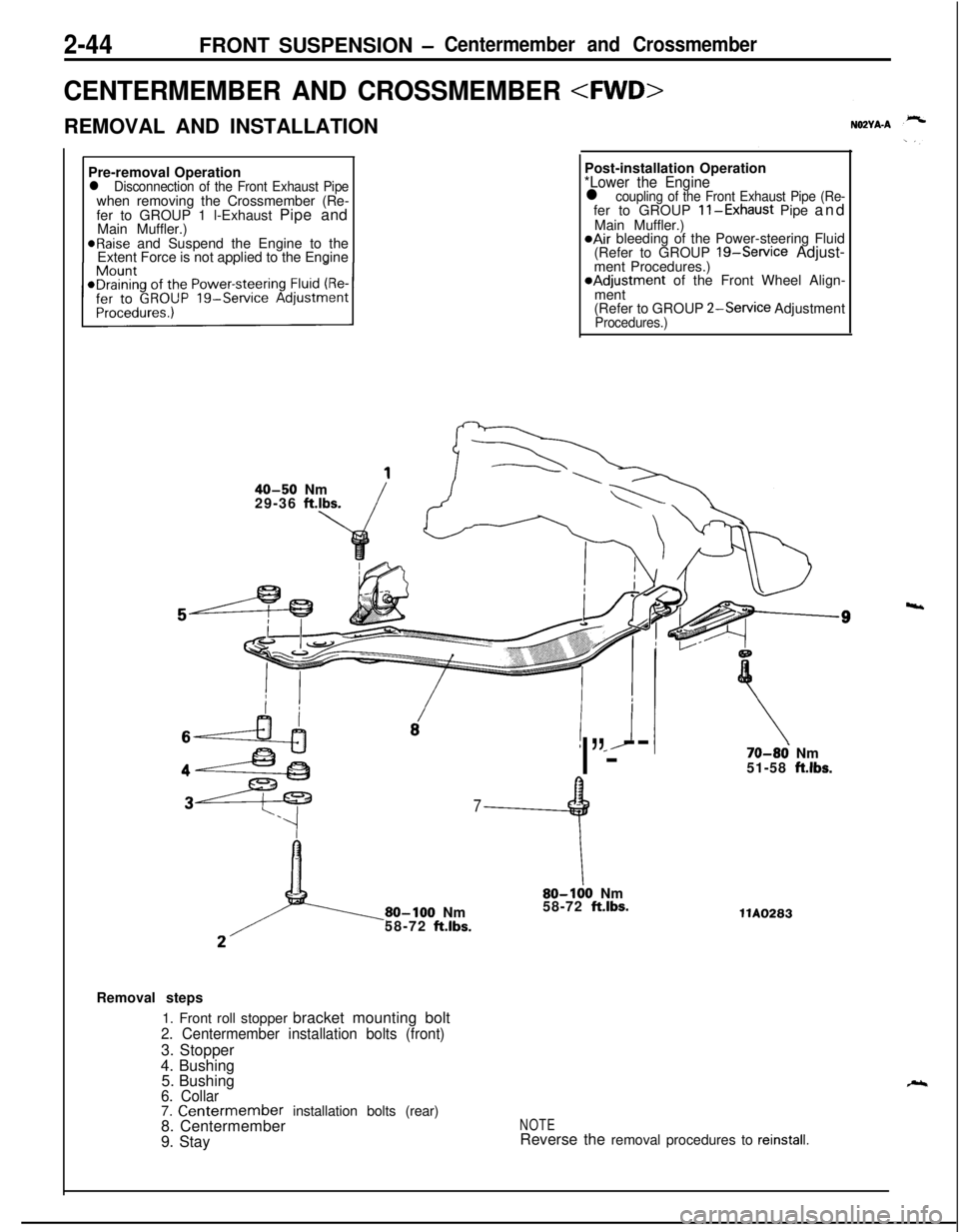
2-44FRONT SUSPENSION -Centermember and Crossmember
CENTERMEMBER AND CROSSMEMBER
REMOVAL AND INSTALLATION
Pre-removal Operation
l Disconnection of the Front Exhaust Pipewhen removing the Crossmember (Re-
fer to GROUP 1 l-Exhaust Pipe and
Main Muffler.)
@Raise and Suspend the Engine to the
Extent Force is not applied to the EnginePost-installation Operation
*Lower the Enginel coupling of the Front Exhaust Pipe (Re-fer to GROUP ll-Exhaust Pipe and
Main Muffler.)
@Air bleeding of the Power-steering Fluid
(Refer to GROUP 19-Service Adjust-
ment Procedures.)*Adjustment of the Front Wheel Align-
ment
(Refer to GROUP
2-Service AdjustmentProcedures.)
40-50 Nm
29-36 ft.lbs.
! *J
I”---
7
9
80-100 Nm
58-72 ft.lbs.
\80-100 Nm
58-72 ft.lbs.
70-86 Nm
51-58 ft.lbs.llA0283
Removal steps
1. Front roll stopper bracket mounting bolt
2. Centermember installation bolts (front)3. Stopper
4. Bushing
5. Bushing
6. Collar7. Centermember installation bolts (rear)
8. Centermember
9. StayNOTEReverse the removal procedures to reinstall.
4
Page 95 of 1216

.-FRONT SUSPENSION
-Centermember and Crossmember2-47
f
39
40-50 Nm
29-36 ft.lbs.
r---
100-120 Nm*
72-87 ft.lbs.*
80-100 Nm
JIY- \I58-72 ftlbs.
80-lb0 Nm 3\7 !58-72 ft.lbs.I
80-100 Nm*58-72 ft.lbs.*
100-120 Nm72-87 ftlbs.35. Self locking nut
36. Clamp37. Lower arm mounting bolt
38. Stopper
39. Rear roll stopper bracket mounting bolt40. Self locking nut
41. Lower plate
42. Crossmember
43. Stopper
44. Bushing
FFEeverse the removal procedures to reinstall.(2) m : Non-reusable parts(3) *: Indicates parts which should be temporarily tight-ened, and then fully tightened with the vehicle in
the unladen condition.
Page 98 of 1216
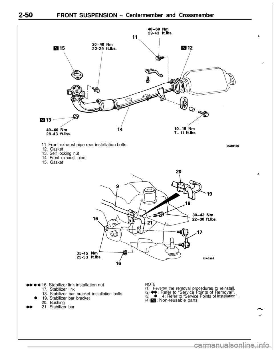
2-50FRONT SUSPENSION -Centermember and Crossmember
40-60 Nm
29-43 ftlbs.
“1I
30-40 Nm
22-29 ftlbs.
40-60 /Nm29-43 ftlbs.
11. Front exhaust pipe rear installation bolts12. Gasket
13. Self locking nut
14. Front exhaust pipe
15. Gasket35-45
25-33
IO-15 Nm7- 11 ftlbs.
22-30 ftlbs.
12AO352
+e MI 16. Stabilizer link installation nut17.Stabilizerlink
18. Stabilizer bar bracket installation boltsl 19. Stabilizer bar bracket20.Bushing
4*21. Stabilizer bar
05AO169
$?everse the removal procedures to reinstall.(2) +* : Refer to “Service Points of Removal”.(3) l 4 : Refer to “Service Points of Installatron”.(4) m : Non-reusable partsA
A’A
ct
J’
Page 100 of 1216
FRONT SUSPENSION - Centermember and Crossmember
34
40-50 Nm
29-36 ftlbs.
38
100-12072-87 ft32
;56-72 ft.lbs.-39
-36
‘350
’ 80-100 Nm
58-72 ft.lbs.
60-100 Nm*58-72 ft.lbs.*
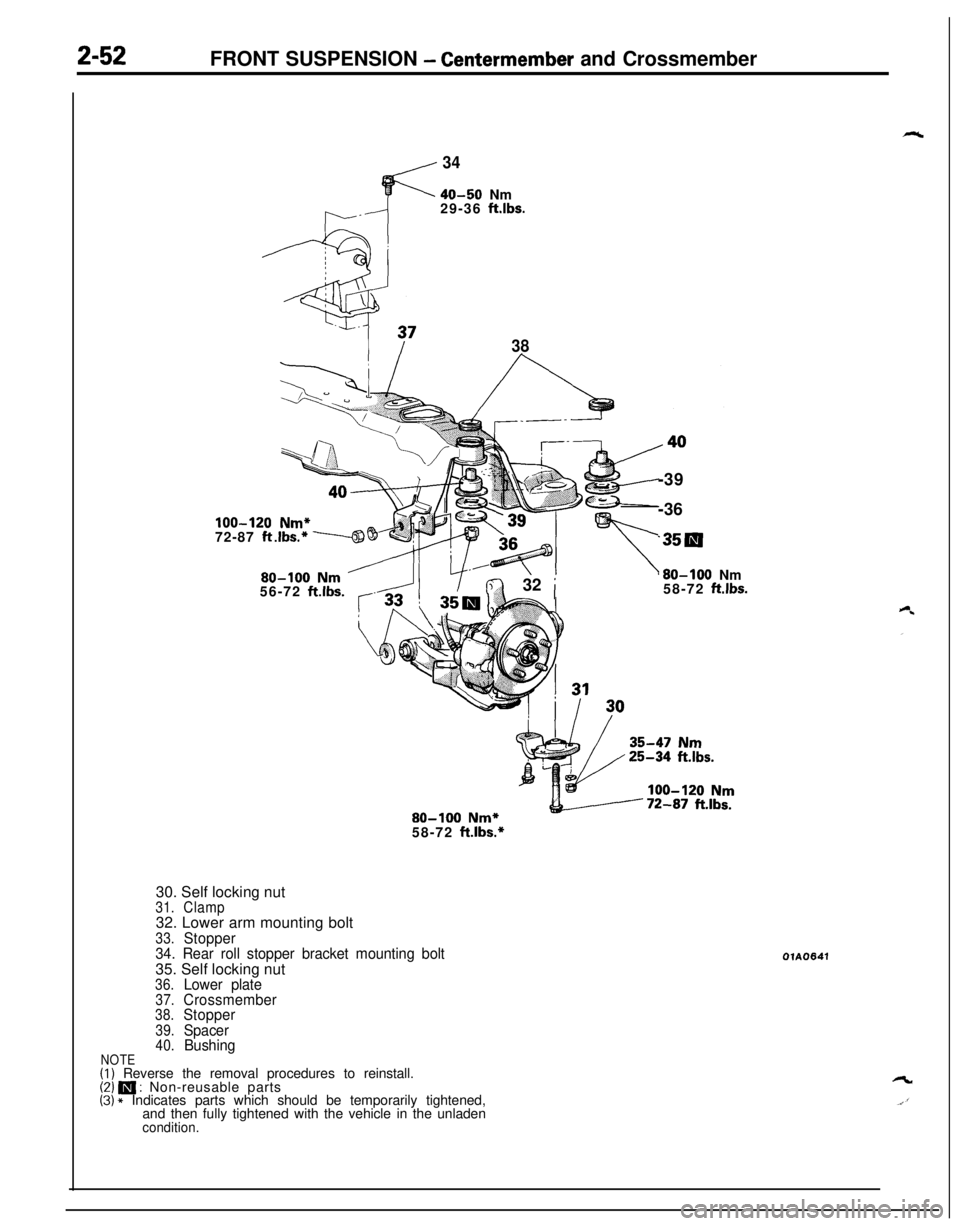
30. Self locking nut
31.Clamp32. Lower arm mounting bolt
33.Stopper
34. Rear roll stopper bracket mounting bolt35. Self locking nut
36.Lower plate37.Crossmember38.Stopper
39.Spacer40.BushingNOTE(1) Reverse the removal procedures to reinstall.(2) m : Non-reusable parts(3) * Indicates parts which should be temporarily tightened,
and then fully tightened with the vehicle in the unladen
condition.
OlA0641
Page 611 of 1216
1 pq
,s I’
:
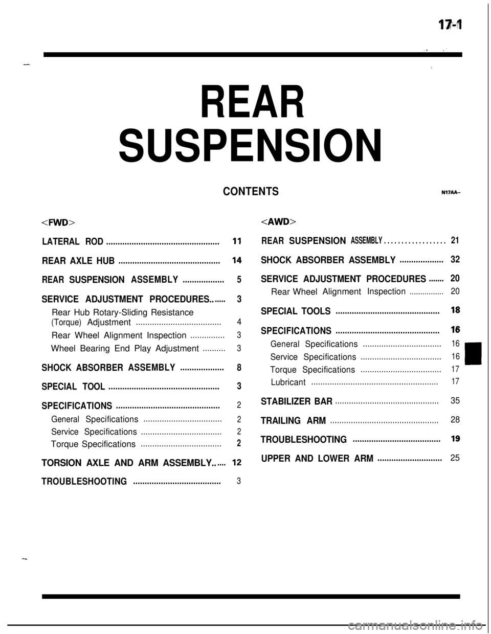
REAR
SUSPENSION
LATERAL ROD.................................................11
REAR AXLE HUB............................................14
REARSUSPENSIONASSEMBLY..................5
SERVICE ADJUSTMENT PROCEDURES.......3Rear Hub Rotary-Sliding Resistance
(Torque)Adjustment.....................................4Rear Wheel Alignment Inspection
...............3Wheel Bearing End Play Adjustment
..........3
SHOCKABSORBERASSEMBLY...................8
SPECIAL TOOL................................................3
SPECIFICATIONS.............................................2
GeneralSpecifications..................................2
ServiceSpecifications...................................2Torque Specifications
...................................2
TORSION AXLE AND ARM ASSEMBLY......12
TROUBLESHOOTING......................................3
REARSUSPENSIONASSEMBLY . . . . . . . . . . . . . . . . . .21
SHOCK ABSORBER ASSEMBLY...................32
SERVICE ADJUSTMENT PROCEDURES.......20Rear WheelAlignment
Inspection................20
SPECIAL TOOLS.............................................18
SPECIFICATIONS.............................................16
GeneralSpecifications..................................16
ServiceSpecifications...................................16LTorqueSpecifications...................................17
Lubricant.......................................................17
STABILIZER BAR. . . . . . . . . . . . . . . . . . . . . . . . . . . . . . . . . . . . . . . . . . . . .35
TRAILING ARM. . . . . . . . . . . . . . . . . . . . . . . . . . . . . . . . . . . . . . . . . . . . . . .28
TROUBLESHOOTING......................................19
UPPER AND LOWER ARM............................25
CONTENTSN17AA-
Page 612 of 1216
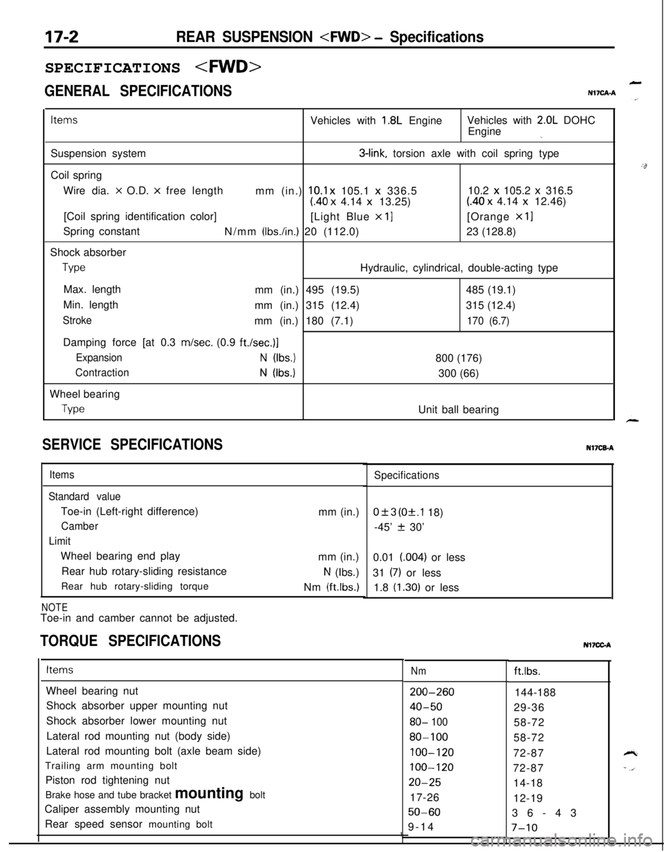
17-2REAR SUSPENSION
GENERAL SPECIFICATIONS
LN17CAA
ItemsVehicles with 1.8L EngineVehicles with 2.0L DOHC
Engine
jSuspension system
3-link, torsion axle with coil spring type
Coil spring
Wire dia.
x O.D. x free length
mm (in.) 10.1 x 105.1 x 336.510.2 x 105.2 x 316.5
(40 x 4.14 x 13.25)(40 x 4.14 x 12.46)
[Coil spring identification color]
[Light Blue
x 11[Orange x 11Spring constant
N/mm
(Ibs./in.) 20 (112.0)23 (128.8)
Shock absorber
TypeHydraulic, cylindrical, double-acting type
Max. length
mm (in.) 495 (19.5)485 (19.1)
Min. length
mm (in.) 315 (12.4)315 (12.4)
Strokemm (in.) 180 (7.1)170 (6.7)Damping force [at 0.3 m/set. (0.9
ft./set.)]
ExpansionN (Ibs.)800 (176)
ContractionN (Ibs.)300 (66)
Wheel bearing
TypeUnit ball bearing
SERVICE SPECIFICATIONS
Items
Standard valueToe-in (Left-right difference)
Camber
LimitWheel bearing end play
Rear hub rotary-sliding resistance
Rear hub rotary-sliding torque
NOTEToe-in and camber cannot be adjusted.mm (in.)
mm (in.)
N (Ibs.)
Nm
(ftlbs.)
TORQUE SPECIFICATIONS
Specifications
0+3 (Of.1 18)
-45’
f 30’
0.01 (004) or less
31
(7) or less
1.8
(1.30) or lessNI’ICB-A
ItemsNmft.lbs.
Wheel bearing nut
Shock absorber upper mounting nut
Shock absorber lower mounting nut
Lateral rod mounting nut (body side)
Lateral rod mounting bolt (axle beam side)
Trailing arm mounting bolt
Piston rod tightening nut
Brake hose and tube bracket mounting bolt
Caliper assembly mounting nut
Rear speed sensor mounting bolt
200-260
40-50
80- 100
80-100
100-120
100-120
20-2517-26
50-609-14144-188
29-36
58-72
58-72
72-87
72-87
14-18
12-19
36-43
I7-10
Nl7CGA
Page 613 of 1216
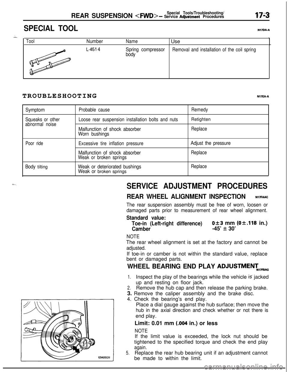
Special Tools/Troubleshooting/REAR SUSPENSION
SPECIAL TOOLN17DA.A
ToolNumberName1 Use1
L-451 4
Spring compressorRemoval and installation of the coil spring
bodyTROUBLESHOOTINGNI’IEA-A
Symptom
Squeaks or other
abnormal noiseProbable cause
Loose rear suspension installation bolts and nuts
Malfunction of shock absorber
Worn bushings
Remedy
Retighten
Replace
Poor rideExcessive tire inflation pressure
Malfunction of shock absorberWeak or broken springs
Adjust the pressure
Replace
Body tiltingWeak or deteriorated bushings
Weak or broken springs
Replace
SERVICE ADJUSTMENT PROCEDURES
REAR WHEEL ALIGNMENT INSPECTIONN17FAAC
The rear suspension assembly must be free of worn, loosen or
damaged parts prior to measurement of rear wheel alignment.
Standard value:
Toe-in (Left-right difference)
Of3 mm (Of.118 in.)
Camber-45’ + 30’
NOTEThe rear wheel alignment is set at the factory and cannot be
adjusted.If toe-in or camber is not within the standard value, replace
bent or damaged parts.
WHEEL BEARING END PLAY ADJUSTMENT,7FBA0
1.Inspect the play of the bearings while the vehicle is jacked
up and resting on floor jack.
2.Remove the hub cap and then release the parking brake.
3. Remove the caliper assembly and the brake disc.
4. Check the bearing’s end play.
Place a dial gauge against the hub surface; then move the
hub in the axial direction and check whether or not there isend play.
Limit: 0.01 mm
(.004 in.) or less
NOTE12AO531If the limit value is exceeded, the lock nut should be
tightened to the specified torque and check the end play
again.
5.Replace the rear hub bearing unit if an adjustment cannot
be made to within the limit.
Page 614 of 1216

17-4REAR SUSPENSION
12A0533
3REAR HUB ROTARY-SLIDING
RESISTANCE
(TORQUE) ADJUSTMENTN17FCAC -
1.Inspect the play of the bearings while the vehicle is jacked.
up and resting on floor jack.
2. Release the parking brake.
3. Remove the caliper assembly and the brake disc.
4. After turnina the hub a few times to seat the bearing,
attach a spriig balance to the hub bolt, and, pulling at a 9@angle from the hub bolt, measure to determine whether or
not the rotary-sliding resistance of the rear hub (the
rotary-sliding torque of the rear hub) is the standard value.
Limit:
Rear hub rotary-sliding resistance
31N (7 Ibs.) or less
Rear hub rotary-sliding torque1.8 Nm (1.30
ft.lbs.) or less
NOTEIf the limit value is exceed, loosen the nut and then tighten
it to the specified torque, and check the rear hub
rotary-sliding torque again.
5. Replace the rear hub bearing unit if an adjustment cannot
+.be made to within the limit.
A
Page 615 of 1216
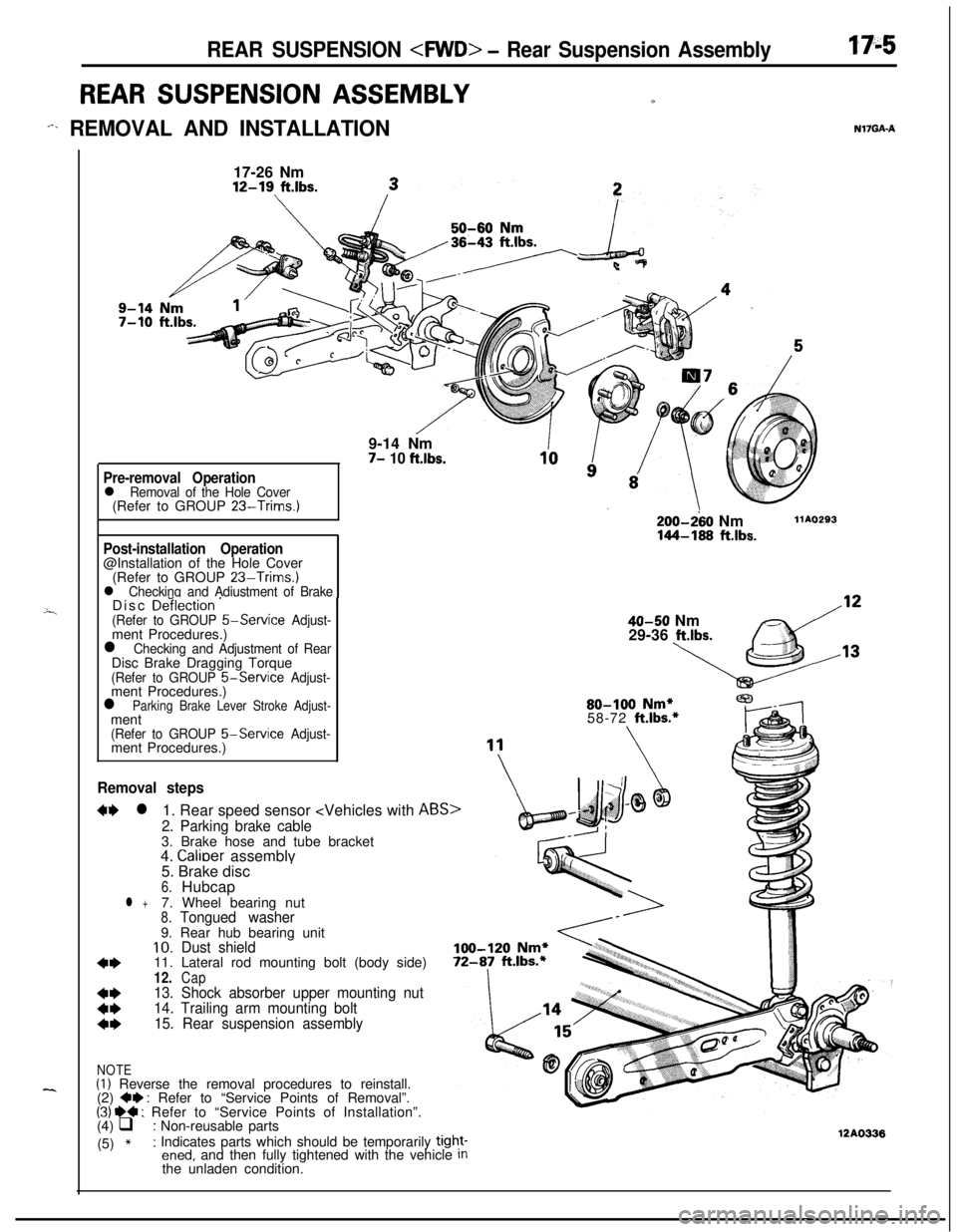
REAR SUSPENSION
REAR SUSPENSION ASSEMBLYu
-%. REMOVAL AND INSTALLATIONN17GAA
---i
--..17-26 Nm12-19
ft.lbs.9-14 Nm
7- 10 ft.lbs.
Pre-removal Operationl Removal of the Hole Cover(Refer to GROUP 23-Trims.)
Post-installation Operation@Installation of the Hole Cover
(Refer to GROUP
23-Trims.)l Checking and Adiustment of BrakeDisc De‘ilection ’(Refer to GROUP 5-Service Adjust-ment Procedures.)
l Checking and Adjustment of RearDisc Brake Dragging Torque
(Refer to GROUP &Service Adjust-ment Procedures.)
l Parking Brake Lever Stroke Adjust-ment
(Refer to GROUP 5-Service Adjust-ment Procedures.)
Removal steps
W l1. Rear speed sensor
2. Parking brake cable3. Brake hose and tube bracket
4.
Calioer assemblv
200-280 Nm144-168 ftlbs.
llAO293
40-50 Nm
29-36 ltlbs.80-100
Nm*58-72 ft.lbs.*5. Brake disc
’6.Hubcapl +7. Wheel bearing nut8.Tongued washer9. Rear hub bearing unit
10.Dust shield
4*11. Lateral rod mounting bolt (body side)12.Cap
t:
13. Shock absorber upper mounting nut
14. Trailing arm mounting bolt
4*15. Rear suspension assembly
NOTE(I) Reverse the removal procedures to reinstall.
(2) +e : Refer to “Service Points of Removal”.(31 ~~ : Refer to “Service Points of Installation”.
(4) q : Non-reusable parts
(5)
*: Indicates parts which should be temporarily tight-ened, and then fully tightened with the vehicle Inthe unladen condition.12AO336